Herunterladen Inhalt Inhalt Diese Seite drucken
Inhaltsverzeichnis

Werbung

Verfügbare Sprachen

Verfügbare Sprachen

CFBI902AN / CFBI902IX / CFBI902OW / CFBI902ZW
GB | INSTRUCTIONS ON MOUNTING AND USE
NL | MONTAGEVOORSCHRIFTEN EN GEBRUIKSAANWIJZING
F | PRESCRIPTIONS DE MONTAGE ET MODE D'EMPLOI
D | MONTAGE- UND GEBRAUCHSANWEISUNG
www.boretti.com

Werbung

Inhaltsverzeichnis
loading

Inhaltszusammenfassung für BORETTI CFBI902AN

  • Seite 1 CFBI902AN / CFBI902IX / CFBI902OW / CFBI902ZW GB | INSTRUCTIONS ON MOUNTING AND USE NL | MONTAGEVOORSCHRIFTEN EN GEBRUIKSAANWIJZING F | PRESCRIPTIONS DE MONTAGE ET MODE D’EMPLOI D | MONTAGE- UND GEBRAUCHSANWEISUNG www.boretti.com...
  • Seite 2 Nederlands Bladzijde 3 Gebruiks-en installatievoorschriften De beschrjvingen en aanduidingen vermeld in de gebruiks-en installatievoorschriften zijn enkel van informatieve aard. De constructeur behoudt zich het recht voor om zonder verwittiging en op gelijk welk ogenblik wijzigingen aan zijn produkten aan te brengen. Deutsch Seite 56 Gebrauchsanweisung Installationsanleitung...
  • Seite 3 Nederlands Gebrauchsanweisung Installationsanleitung Mevrouw, Juffrouw, Mijnheer, U heeft onlangs een van onze fornuizen aangekocht en wij danken u voor uw vertrouwen. Uw fornuis werd met de grootste zorg ontworpen, vervaardigd en getest met het oog op uw volkomen tevredenheid. Opdat u het optimaal zou kunnen gebruiken en de gewenste resultaten zou bereiken, bevelen wij aan deze GEBRUIKSHANDLEIDING aandachtig te lezen.
  • Seite 4 BELANGRIJKE VEILIGHEIDSINSTRUCTIES EN AANBEVELINGEN BELANGRIJK: toestel enkel ontworpen geproduceerd voor het koken van huishoudelijk voedsel en is niet geschikt voor enige niet-huishoudelijke toepassing. Om die reden mag het niet gebruikt worden in een commerciële omgeving. De garantie van het toestel vervalt wanneer het toestel wordt gebruikt in een niet-huishoudelijke omgeving, d.w.z.
  • Seite 5 • Probeer niet om de technische eigenschappen van dit toestel te wijzigen, aangezien dat gevaar bij het gebruik kan veroorzaken. De producent is niet aansprakelijk voor ongemak door niet- naleving van deze instructie. • Gebruik het toestel niet met een externe timer of een afzonderlijk afstandsbedieningssysteem •...
  • Seite 6 • De producent is niet aansprakelijk voor letsels van personen of schade aan eigendom door incorrect of ongepast gebruik van het toestel. • WAARSCHUWING: Tijdens het gebruik worden het toestel en de bereikbare onderdelen heet; ook na gebruik blijven deze nog enige tijd heet.
  • Seite 7 • EERSTE GEBRUIK VAN DE OVEN – volg deze instructies: Richt de binnenkant van de oven in zoals beschreven in het – hoofdstuk ‘REINIGING EN ONDERHOUD’. Zet de lege oven op de maximumstand om vet van de – verwarmingselementen te verwijderen. Koppel het toestel los van de elektriciteit, laat de oven afkoelen –...
  • Seite 8 • Het apparaat mag niet achter een front worden geïnstalleerd om oververhitting te voorkomen. • De ovenaccessoires (zoals bijvoorbeeld ovenrekken) dienen correct te worden geïnstalleerd zoals aangegeven op pagina 38. • Indien het aansluitsnoer beschadigd is, mag dit uitsluitend worden vervangen door een geautoriseerde monteur om risico’s te voorkomen.
  • Seite 9: Energie-Etikettering/Ecologisch Ontwerp

    ENERGIE-ETIKETTERING/ECOLOGISCH ONTWERP • Gedelegeerde verordening (EU) Nr. 65/2014 van de commissie (houdende aanvulling van Richtlijn 2010/30/EU van het Europees Parlement en de Raad). • Verordening (EU) Nr. 66/2014 van de commissie (tot uitvoering van Richtlijn 2009/125/EG van het Europees Parlement en de Raad). Verwijzing naar de meet- en berekeningsmethoden die gebruikt zijn om de overeenstemming met bovenstaande eisen vast te stellen: •...
  • Seite 10 OPGELET – HEEL BELANGRIJK ! BRAND/OVERVERHITTINGSGEVAAR: • Geen servetten, lappen of andere voorwerpen op de kookplaatbescherming of de handgreep/handgrepen van de ovendeur aanbrengen terwijl het apparaat werkt of warm is. OM SCHADE AAN HET APPARAAT TE VOORKOMEN: • Het beschermende blad of de handgreep/handgrepen van de ovendeur niet gebruiken om het fornuis op te heffen/te verplaatsen.
  • Seite 11 KOOKTAFEL Afb. 1.1 KOOKZONES Normaal vermogen: 2300 W 1. Inductie kookzone Ø 200 mm Maximaal ‘BOOST’ vermogen: 3000 W 2. Inductie kookzone Ø 160 mm Normaal vermogen: 1400 W 3. Kookzonedisplay Opmerking: het normale en maximale vermogen kan veranderen afhankelijk van de grootte en materiaal van de kookpan op the kookplaat.
  • Seite 12: Beschrijving Van De Bedieningsknoppen

    BEDIENINGSPANEEL Afb. 2.1 BESCHRIJVING VAN DE BEDIENINGSKNOPPEN Bedieningsknop kookplaat rechtsvoor Bedieningsknop kookplaat rechtsachter Bedieningsknop kookplaat linksachter Bedieningsknop kookplaat linksvoor Schakelaar van de multifunctionele oven (oven links) Thermostaatknop van de multifunctionele (oven links) Thermostaatknop van de traditionele oven (oven rechts) Schakelaar van de traditionele oven (oven rechts) Elektronische klok/programmeur (alleen de grote oven links) Controlelampje: 10.
  • Seite 13: Gebruik Van De Inductiekookplaat

    GEBRUIK VAN DE INDUCTIEKOOKPLAAT De vitrokeramische kookplaat is uitgerust met inductiekookzones. Deze zones, aangeduid met gedrukte cirkels op het keramisch oppervlak, worden geregeld door aparte bedieningsknoppen op de display. Vooraan in het midden van de kookplaat duidt de display (bestaande uit 4 verlichtte cijfers - één voor elke zone - het volgende aan: = Kookzone OFF niet ingeschakeld Afb.
  • Seite 14 INDICATOR VOOR OVERBLIJVENDE WARMTE Wanneer de kookzone nog heet is, zal de respectievelijke indicator voor overblijvende warmte op de display in werking zijn om u voor het hete oppervlak opmerkzaam te maken. Raak de kookzone van de kookplaat niet aan. Let vooral op kinderen. Wanneer de op de display verlicht is, is het mogelijk om opnieuw te beginnen koken.
  • Seite 15 BEDIENINGSKNOPPEN Elke kookzone kan worden ingesteld met een individuele bedieningsknop die op het controlepaneel staat. Het koken wordt geregeld door een elektronisch systeem. Indien een kookzone niet uitgeschakeld is (OFF), zal het elektronisch systeem deze automatisch uitschakelen na een vooropgestelde tijd die afhankelijk is van het kookvermogen.
  • Seite 16 1 ÷ 9 KOOKVERMOGEN Draai de bedieningsknop met de wijzers van de klok mee tot aan het gewenste kookvermogen tussen 1 (minimum) en 9 (maximum). Het kookvermogen kan op eender welk moment veranderd worden door de bedieningsknop met de wijzers van de klok of tegen de wijzers van de klok naar een ander kookvermogen te draaien.
  • Seite 17 FUNCTIE ‘SNELKOKEN’ Draai de bedieningsknop tegen de wijzers van de klok in tot aan en laat de bedieningsknop los (na de “beep”); het respectievelijke symbool zal verschijnen. Draai de bedieningsknop binnen 5 seconden tot aan het gewenste kookvermogen (tussen 1 en 9);...
  • Seite 18 MAXIMUM BESCHIKBAAR VERMOGEN VOOR DE KOOKZONES De rechter- en linkerkookzone werken met twee Electronisch afzonderlijk electronische circuits en het maximum circuit 1 vermoger per circuit is 3700 W. Indien een kookzone meer dan 3700 W nodig heeft, dan heeft het laatste kookvermogen voorrang en zal het kookvermogen van de andere kookzone automatisch verminderd worden naar het overgebleven beschikbaar vermogen.
  • Seite 19 FOUTMELDINGEN OP DE KOOKZONEDISPLAY Foutmelding Voorbeeld Wat te doen Schakel het fornuis en de electrische stroom uit Erxx of Wacht 1 minuut en schakel het fornuis en Ex (niet E2 of de kookzones aan. Wacht 1 minuut en indien de foutmelding niet meer verschijnt, kunnen de kookzones opnieuw gebruikt worden.
  • Seite 20 RAAD VOOR HET VEILIG GEBRUIK VAN DE KOOKPLAAT • Controleer welke knop de gekozen kookzone bedient voordat u aan de knoppen draait. Het is raadzaam de pan op de kookzone te zetten voordat u deze aan zet, en de pan te verwijderen wanneer het koken klaar is.
  • Seite 21 REINIGING • Vooraleer u de kookplaat reinigt, dient u na te gaan of het toestel uitgeschakeld is. • Volg de schoonmaakinstructies nauwgezet op. • Verwijder eventuele voedselresten of andere stoffen die zich habben vastgezet. • Verwijder stof met een vochtige doek. •...
  • Seite 22: Elektrische Multifunktie Oven (Oven Links)

    ELEKTRISCHE MULTIFUNKTIE OVEN (oven links) WERKINGSPRINCIPE Opgelet : Tijdens de werking van de oven is de H e t o p w a r m e n e n k o k e n m e t d e MULTIFUNKTIE oven gebeurt als volgt: ovendeur warm.
  • Seite 23 Afb. 4.1 Afb. 4.2 THERMOSTAAT (afb. 4.1) De verwarmingselementen van de oven worden ingeschakeld door de knop op de gewenste funktie te plaatsen en door de thermostaatknop op de gewenste temperatuur in te stellen. De controle van de werking (ON-OFF) van de verwarmingselementen wordt uitgevoerd door de thermostaat;...
  • Seite 24 ROOSTEREN MET DE GRILL Werking van de elektrische weerstand met infra-roodstraling. Met de ovendeur dicht gebruiken en met de thermostaatknop op een stand tussen 50° en 225°C voor ten hoogste 15 minuten en vervolgens op 175°C. De grill niet langer dan 30 min. gebruiken. Opgelet : tijdens de werking van de oven is de ovendeur warm.
  • Seite 25 KOKEN MET GEVENTILEERDE GRILL Werking van de infra-roodgrillweerstand en de turbine. De warmte wordt hoofdzakelijk verspreid door straling en de ventilator verdeelt de warmte over de ganse oven. De temperatuur moet d.m.v. de thermostaatknop worden geregeld op een stand tussen 50° en 200° (voor maximaal 30 minuten). De oven moet voorverwarmd worden gedurende 5 minuten.
  • Seite 26 KOOKWENKEN SIMULTAAN KOKEN De standen de MULTIFUNKTIE STERILISEREN oven laten toe verschillende heterogene Het steriliseren van levensmiddelen in bereidingen simultaan te koken. Aldus kan bokalen gebeurt als volgt (volle bokalen, men tezelfdertijd verschillende gerechten hermetisch gesloten): koken zoals vb. vis, taart en vlees zonder dat de aroma’s en smaken zich a.
  • Seite 27: Koken Met De Grill

    KOKEN MET DE GRILL Ter informatie geven we in volgende t a b e l e n k e l e g e r e c h t e n m e t h u n De oven moet voorverwarmd worden bereidingstemperauren in °C.
  • Seite 28 ELEKTRISCHE OVEN MET NATUURLIKE CONVECTIE (oven rechts) OPMERING: Opgelet : Alvorens de oven voor de eerste keer te Tijdens de werking van de oven is de gebruiken, de oven leeg aanzetten. Stel ovendeur warm. d e h o o g s t e s t a n d i n e n z e t d e Houdt de jonge kinderen op afstand.
  • Seite 29 BAKSTANDENSCHAKELAAR (afb. 5.1) ROOSTEREN MET DE Draai de knop met de klok mee om één van GRILL de bakstanden in te stellen. Werking van de elektrische weerstand met infra-roodstraling. THERMOSTAAT (afb. 5.2) Met de ovendeur dicht gebruiken en De verwarmingselementen van de oven met de thermostaatknop op een stand worden ingeschakeld door de knop op tussen 50°...
  • Seite 30 Ter informatie geven we in volgende KOKEN MET DE OVEN t a b e l e n k e l e g e r e c h t e n m e t h u n De oven voorverwarmen op de gewenste bereidingstemperauren in °C.
  • Seite 31: Gebruik Van Het Braadspit

    BRAADSPIT GEBRUIK VAN HET BRAADSPIT (afb. 5.3) (afb. 5.3) De f o rn u iz en u i tge r us t m e t e en braadspit. • De braadslee op de onderste richel van de oven plaatsen en de steun op Dit dient om de gerechten aan het spit le de middenrichel.
  • Seite 32: Elektronische Digitale Programmering

    ELEKTRONISCHE DIGITALE PROGRAMMERING De elektronische programmering is een mechanisme met de volgende functies: • 24-uurs klok met lichtgevend display • Kookwekker (in te stellen tot aan 23 uur en 59 minuten) • Programma voor automatisch bakken in de oven. • Programma voor half-automatisch bakken in de oven.
  • Seite 33 DIGITAALKLOK ELEKTRONISCHE KOOKWEKKER (afb. 6.2) De programmeer-eenheid is voorzien van De kookwekkerfunctie bestaat slechts een elektronische klok met lichtgevende uit een geluidssignaal dat ingesteld kan cijfers die de uren en de minuten aangeven. worden voor een tijdsbestek van maximaal Bij de eerste aansluiting van de oven op 23 uur en 59 minuten.
  • Seite 34: Automatisch Bakken

    AUTOMATISCH BAKKEN Stel de temperatuur en de bakfunctie (afb. 6.5 - 6.6) in met behulp van de schakelaar en Voor het automatisch bakken in de oven de thermostaat van de oven (zie de moet U: betreffende hoofdstukken). De baktijd instellen Einde baktijd instellen De oven is nu geprogrammeerd en alle zal Temperatuur en functie van de oven...
  • Seite 35: Halfautomatisch Bakken

    HALFAUTOMATISCH BAKKEN oven onmiddellijk worden ingeschakeld en na het verstrijken van de deze instelling gaat oven ingestelde tijd of bij het bereiken van het automatisch uit na de gewenste baktijd. Er als einde baktijd ingestelde tijdstip zal hij zijn twee manieren om half-automatisch te automatisch weer worden uitgeschakeld.
  • Seite 36 BELANGRIJK – OVEN WERKT NIET Als de oven niet werkt, is het mogelijk dat deze per ongeluk op “AUTOMATIC” staat, of dat het apparaat tijdelijk geen stroom heeft gehad. Indien de timer “AUTO” aangeeft, of de tijd aan het knipperen is, kan de Oven mogelijk niet worden aangezet of reageert deze vertraagd.
  • Seite 37 ONDERHOUD ALGEMENE RAADGEVINGEN EMAIL • Ga nooit over tot onderhoud of De geëmailleerde delen mogen enkel reiniging van het toestel zonder schoongemaakt worden met een spons en dat u het vooraf van het stroomnet zeep of andere nietschurende middelen. heeft afgekoppeld. Bij voorkeur met een zachte doek.
  • Seite 38 MONTEREN EN DEMONTEREN OVENRUIMTE VAN DE ZIJPLATEN Maak de ovenruimte na iedere kookbeurt schoon. Voor de schoonmaak de rekken • Bevestig de uitneembare zijplaten aan de zijkanten van de oventuimte aan de gaten van de zijwanden in de uitnemen en deze terugmonteren als u oven (afb.
  • Seite 39: Dragers Telescopische Verschuifbare Leggers

    DRAGERS TELESCOPISCHE VERSCHUIFBARE LEGGERS (afb. 7.3) De dragers van ons telescopisch systeem met verschuifbare leggers maken het veiliger en eenvoudiger om de roosters in en uit de oven te halen. De drager blokkeert indien deze niet verder kan worden uitgetrokken. Belangrijk! Volg bij het plaatsen van de dragers de volgende stappen: •...
  • Seite 40 VERVANGEN OVENLAMPJE LET OP: Wees zeker dat het apparaat uitgeschakeld is alvorens de ovenlamp WRONG te vervangen om elektrische schokken FOUT te vermijden. • laat indien nodig oven verwarmingselementen afkoelen. • Trek de stekker uit het stopcontact. CORRECT GOED • Verwijder het verlichtingskapje “A”...
  • Seite 41 VERWIJDEREN EN TERUGPLAATSEN VAN HET BINNENGLAS VAN DE OVENDEUR Als u het glas aan de binnenkant van de deur wilt schoon maken, dan is het belangrijk dat u de volgende instructies zorgvuldig uitvoert. Het verkeerd terugplaatsen van de glasplaat kan leiden tot schade aan het apparaat en kan de garantie laten vervallen.
  • Seite 42 VERWIJDEREN VAN DE OVENDEUR U verwijdert de ovendeur zonder moeite als volgte: • Open de deur volledig (afb. 7.11). • Open volledig hefboom “A” aan de linkse en rechtse scharnieren (afb. 7.12). • Houd de deur vast zoals aangeduid in afb.
  • Seite 43 OVENDEUREN - HET REINIGEN VAN DE RUITEN De ovendeur beschikt over 3 ruiten: • nr 1: buitenzijde; • nr 1: binnenzijde; • nr 1: middelste. Om beide zijdes te kunnen reinigen, moet Afb. 7.15 u de binnenruit als volgt verwijderen: UITNEMEN VAN DE BINNENSTE EN MIDDELSTE RUITEN Zorg ervoor dat de deur vergrendeld...
  • Seite 44 Verwijder de middelste ruit: • Maak de middelste ruit voorzichtig los uit de onderste klemmen door hem te bewegen zoals in afb. 7.20. • Til de onderrand van de ruit voorzichtig op (pijl 1 in afb. 7.22) en verwijder hem door hem uit de bovenste klemmen te trekken (pijl 2 in afb.
  • Seite 45 TERUGPLAATSEN MIDDELSTE EN BINNENSTE RUITEN Zorg ervoor dat de deur vergrendeld is in de open stand (zie afb. 7.17) Plaats de middelste ruit terug: • Controleer of de vier rubber blokjes aangebracht zijn (“M” in afb. 7.23) • Controleer of u de ruit op de juiste manier vasthoudt.
  • Seite 46 Plaats de binnenste ruit: • Controleer of de vier rubber blokjes aangebracht zijn (“D” in afb. 7.26). • Controleer of u de ruit op de juiste manier vasthoudt. De woorden die erop staan moeten leesbaar zijn wanneer de ruit naar u gekeerd is. •...
  • Seite 47 Aanwijzingen voor de installateur BELANGRIJK • De installatie mag uitsluitend worden uitgevoerd door een gekwalificeerd elektricien, in overeenstemming met de lokaal geldende voorschriften en de aanwijzingen van de fabrikant. Als hieraan niet wordt voldaan, vervalt de garantie. • Het toestel moet overeenkomstig verordeningen van kracht in uw land en in observa- tie van de instructies van de fabrikant worden geïnstalleerd.
  • Seite 48: Installation

    INSTALLATION Dit toestel behoort tot beschermingsklasse “2/1” tegen de oververhitting van aangrenzende oppervakken. Tussen het toestel en de muur of kast ernaast moet minstens 200 mm afstand bewaard worden (afb. 8.1). De meubelwanden moeten bestand zijn tegen een temperatuur van 75 °C boven de omgevingstemperatuur.
  • Seite 49 ACHTERSCHERM Assembleer het achterscherm “C” (afb. 8.2) alvorens het fornuis te installeren. • Het achterscherm “C” vindt u in de verpakking achter het fornuis. • Verwijder de beschermfolie en plakband voordat u het achterscherm assembleert. • Verwijder de twee afstandsringen “A” en de schroef “B” van de achterkant van de kookplaat.
  • Seite 50 BEWEGINGSSYSTEEM VAN HET FORNUIS WAARSCHUWING Het rechtop zetten van het fornuis moet altijd door twee personen worden gedaan, om te voorkomen dat de verstelbare voeten schade oplopen tijdens deze manœuvre (afb. 8.4). WAARSCHUWING Pas op: til het fornuis bij het rechtop zetten niet op aan de deurhendel (afb.
  • Seite 51 BEVESTIGINGSSTEUN Waarschuwing: Om te vermijden dat het apparaat toevallig kantelt, moet het ondersteund worden door een steun aan de achterzijde van het apparaat te plaatsen en het veilig aan de muur te bevestigen. Om de bevestigingssteun te plaatsen: 1. Bepaal de plaats van het fornuis. Duid op de muur de plaats aan waar de twee schroeven van de bevestigingssteun moeten komen.
  • Seite 52: Elektrisch Gedeelte

    ELEKTRISCH GEDEELTE Als de elektrische voorziening in uw woning BELANGRIJK: aansluiting aangepast moet worden om het toestel te het elektriciteitsnet moet uitgevoerd installeren, laat de nodige werkzaamheden worden door een bevoegd vakman dan verrichten door een bevoegd vakman. voldoen geldende voorschriften.
  • Seite 53 A A N S L U I T E N V A N H E T DOORMETER AANSLUITSNOER VOEDINGSDRAAD “Type H05RR-F” LET OP: Indien de voedingskabel beschadigd is, mag deze uitsluitend 230 V ac 3 x 6 mm (**) vervangen worden door vertegenwoordigde operator van de...
  • Seite 54 230 V~ 230 V ac N (L2) 1 2 3 4 5 230 V~ N (L 400 V 3N~ 400 V 3N ac 1 2 3 4 5 400 V 3N~ 400 V 2N~ 400 V 2N ac 1 2 3 4 5 400 V 2N~ Afb.
  • Seite 56 Deutsch Gebrauchsanweisung installationsanleitung Sehr geehrte Kunden, Wir danken Ihnen für das Vertrauen, das Sie uns mit dem Kauf eines unserer Haushaltsgeräte entgegengebracht haben. Die im folgenden aufgerührten Hinweise und Ratschläge dienen Ihrer Sicherheit und der anderer Personen und ermöglichen Ihnen, alle Gebrauchsweisen des Gerätes kennenzulernen.
  • Seite 57: Wichtige Sicherheitsmassnahmen Und Sicherheitshinweise

    WICHTIGE SICHERHEITSMASSNAHMEN UND SICHERHEITSHINWEISE WICHTIG: Dieses Gerät wurde ausschließlich zum Kochen von Nahrungsmitteln im privaten Haushalt entwickelt und angefertigt und ist nicht für die Anwendung außerhalb des Haushalts geeignet. Daher darf es nicht im gewerblichen Bereich eingesetzt werden. Die Garantie des Geräts wird aufgehoben, wenn das Gerät außerhalb des privaten Haushalts verwendet wird, d.h.
  • Seite 58 • Versuchen Sie nicht, die technischen Eigenschaften des Geräts zu verändern, da dadurch der Gebrauch des Geräts gefährlich werden kann. Der Hersteller übernimmt keine Verantwortung für Unannehmlichkeiten, die aus der Nichtbeachtung dieser Bedingung resultieren. • Geräte nicht mittels einer externen Schaltuhr oder einem separaten Fernsteuerungssystem bedienen.
  • Seite 59 • Dieses Gerät darf von Kindern ab acht Jahren und von Personen mit eingeschränkten körperlichen, sensorischen oder geistigen Fähigkeiten oder mit Mangel an Erfahrung und Kenntnissen verwendet werden, wenn diese beaufsichtigt werden oder Anweisungen in Bezug auf den sicheren Gebrauch des Geräts bekommen und die damit verbundenen Gefahren erkennen.
  • Seite 60 • ACHTUNG: Im Fall einer vorschriftsgemäßen Montage wird ihr Produkt allen Sicherheitsanforderungen gerecht, die für diese Art von Produktkategorie festgelegt wurden. Allerdings ist auf der Rück- oder Unterseite des Geräts besondere Vorsicht geboten, da diese Bereiche nicht zum Berühren entwickelt wurden und sich dort scharfe oder raue Teile befinden könnten, die Verletzungen verursachen können.
  • Seite 61 • Beim Öffnen der Ofentür immer zurückstehen, damit Dampf und heiße Luft entweichen können bevor Sie die Speise herausnehmen. • SICHERER UMGANG MIT LEBENSMITTELN: Die Lebensmittel vor und nach dem Kochen so kurz wie möglich im Ofen lassen. Dadurch kann vermieden werden, dass Lebensmittel von Organismen befallen werden, was eine Lebensmittelvergiftung zur Folge haben kann.
  • Seite 62 Bleiben Sie von den elektromagnetischen Feldern 5-10 cm – während des Kochens entfernt. Verwenden Sie wenn möglich die hinteren Kochzonen. Magnetische Gegenstände (wie Kreditkarten, Disketten, – Speicherkarten) und elektronische Geräte (z.B. Computer) sollten nicht in der Nähe der Induktions-Kochmulde aufbewahrt bzw.
  • Seite 63: Verwendung Des Geräts, Energiespartips

    ENERGIEVERBRAUCHSKENNZEICHNUNG/ÖKODESIGN • Delegierte Verordnung (EU) Nr. 65/2014 der Kommission (zur Ergänzung der Richtlinie 2010/30/EU des Europäischen Parlaments und des Rates im Hinblick). • Verordnung (EU) Nr. 66/2014 der Kommission (zur Durchführung der Richtlinie 2009/125/EG des Europäischen Parlaments und des Rates im Hinblick). Kurze Bezeichnung der bei der Überprüfung der Übereinstimmung mit den vorstehenden Anforderungen angewandten Mess- und Berechnungsmethoden oder Bezugnahme darauf: •...
  • Seite 64 ACHTUNG – SEHR WICHTIG ! BRAND/ÜBERHITZUNGSGEFAHR: • Keine Servietten, Tücher oder Sonstiges an die Schutzschiene des Geräts oder an den/die Griff/e der Ofentür hängen, während das Gerät in Betrieb ist. UM SCHÄDEN AM GERÄT ZU VERMEIDEN: • Das Gerät nicht an der Schutzschiene oder an dem/den Griff/en der Ofentür heben.
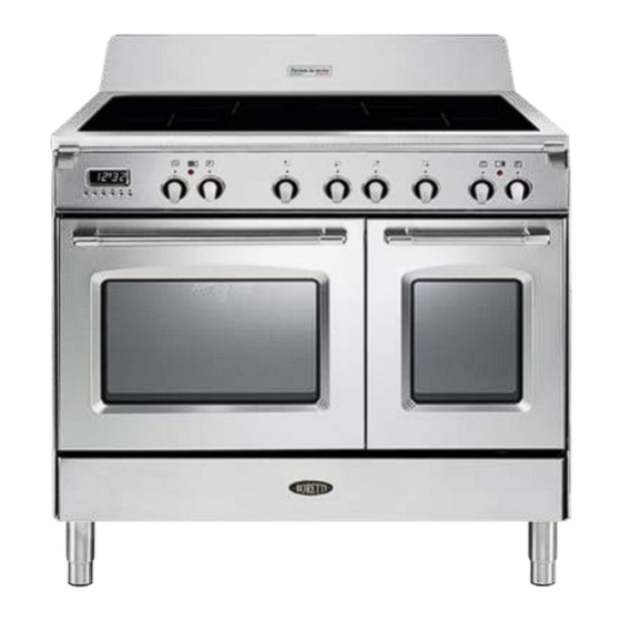
  • Seite 65 ARBEITSFLÄCHE Abb. 1.1 INDUKSTIONS-KOCHMULDE 1. Induktions-Kochzone Ø 200 mm Normal Leistung: 2300 W Booster-Leistung: 3000 W 2. Induktions-Kochzone Ø 160 mm Normal Leistung: 1400 W 3. Display der Kochzonen Hinweis: Die Nennleistung und die Booster-Leistung sind von der Größe und dem Material des Kochgeschirrs abhängig, das auf die Kochzone gestellt wird.
  • Seite 66: Beschreibung Der Bedienelemente

    BEDIENUNGSTELD Abb. 2.1 BESCHREIBUNG DER BEDIENELEMENTE Stellknauf Kochzone vorne rechts Stellknauf Kochzone hinten rechts Stellknauf Kochzone hinten links Stellknauf Kochzone vorne links Mehrzweck-Ofenbedienknopf (Ofen links) Mehrzweck-Ofenthermostatknopf (Ofen links) Herkömmlicher Ofenthermostatknopf (Ofen rechts) Herkömmlicher Ofenbedienknopf (Ofen rechts) Elektronische Uhr/Programmiergerät (Nur linker Hauptofen) Kontrolllampen: 10.
  • Seite 67: Gebrauch Des Kochfeldes

    GEBRAUCH DES KOCHFELDES Die Keramikkochplatte ist mit Induktionskochfeldern ausgestattet. DIese Bereiche, die immer durch farbige Ringe auf der Keramikoberfläche markiert sind, werden mit separaten Knöpfen auf dem Bedienfeld gesteuert. Im vorderen mittleren Bereich des Kochfeldes geben die Bereichsanzeigen (bestehend aus 4 Leuchtfiguren - eine pro Gebiet) angezeigt: = Kochfeld (nicht aktiviert) Abb.
  • Seite 68: Anzeige Der Restwärme

    ANZEIGE DER RESTWÄRME Wenn die Temperatur eines Kochfeldes noch hoch ist, leuchtet jeweils die Anzeige der Rest- wärme auf dem Display auf, um Sie auf die heiße Oberfläche aufmerksam zu machen. Vermeiden Sie es, die heiße Oberfläche im Kochfeld zu berühren. Achten Sie dabei besonders auf Kinder.
  • Seite 69 STEUERKNÖPFE Jedes Kochfeld wird mit einem separaten Steuerknopf bedient, der sich auf dem Bedienfeld befindet. Der Vorgang wird durch das elektronische System gesteuert. Wird ein Kochfeld nicht ausgeschaltet, nimmt das elektronische System die Abschaltung automatisch nach einer vorab eingerichteten Zeit vor, die von der Leistungseinstellung abhängt.
  • Seite 70: Beispiele Für Die Einstellung Der Garleistung

    1 ÷ 9 LEISTUNGSSTUFE Drehen Sie den Knopf im Uhrzeigersinn, um die gewünschte Leistungsstufe zwischen 1 (Minimum) und 9 (Maximum) einzurichten. Das Leistungsstufe kann jederzeit durch Drehen des Knopfes im Uhrzeigersinn oder entgegengesetzt zum Uhrzeigersinn in eine andere Einstellung geändert werden. Das Display des Kochfeldes zeigt die gewählte Einstellung an.
  • Seite 71: "Booster"-Funktion

    FUNKTION “SCHNELLES WÄRMEN” Drehen Sie den Steuerknopf entgegen dem Uhrzeigersinn auf die Einstellung lassen Sie ihn los (nach dem Signalton). Das entsprechende Symbol erscheint auf dem Display des Kochfeldes. Drehen Sie den Knopf innerhalb von 5 s auf die gewünschte Leistungsstufe (zwischen 1 und 9).
  • Seite 72: Maximal Für Die Kochfelder Verwend- Bare Leistung

    MAXIMAL FÜR DIE KOCHFELDER VERWEND- BARE LEISTUNG Das rechte und linke Kochfeld wird durch zwei separate Gesteuert von 1. Leistungsplatine Leistungsplatinen gesteuert und die maximale Ge saamtleistung für jede Platine beträgt 3700 W. Sollten die Kochfelder einer Leistungsplatine mehr als 3700 W erfordern, hat die zuletzt gewählte Leistungsstufe Vorrang und die Leistung des anderen Kochfeldes wird automatisch auf die verbleibende Restleistung reduziert.
  • Seite 73: Ehlercodes Auf Dem Display Des Kochfeldes

    EHLERCODES AUF DEM DISPLAY DES KOCHFELDES Fehlercode Beispiel Maßnahmen Schalten Sie den Herd aus und trennen Sie die Stromversorgung vom Netz. Erxx Warten Sie etwa 1 min ab, schließen Sie den oder Herd wieder an und schalten Sie die Kochfelder Ex (nicht E2 oder ein.
  • Seite 74: Ratschläge Für Einen Sicheren Gebrauch Der Kochmulde

    RATSCHLÄGE FÜR EINEN SICHEREN GEBRAUCH DER KOCHMULDE • Vor dem Einschalten, kontrollieren welcher Einstellknopf für die gewünschte Kochzone betätigt werden soll. Wir empfehlen den Topf vor dem Einschalten auf die Kochzone zu stellen und ihn nach dem Ausschalten zu entfernen. Kochgeschirr mit ebenen und flachen •...
  • Seite 75 REINIGUNG • Achten Sie darauf, daß das Kochfeld abgeschalten ist, bevor Sie es reinigen. • Die Anweisungen zur Reinigung auf jeden Fall beachten. • Entfernen Sie eventuelle Yerkrustungen nur mit dem Schaber. • Entfernen Sie Staub mit einem feuchten Lappen. •...
  • Seite 76: Technische Daten Des Multifunktions-Backofens

    MULTIFUNKTIONS-BACKOFENS (Ofen links) FUNKTIONSWEISEN Vorsicht: Die Backofentür wird Das Erhitzen und Garen im Multi- während des Betriebs sehr heiß. funktions-Backofen wird auf die wie folgt Halten Sie Kinder fern. beschriebenen Weisen erreicht: a. Durch natürliche Wärmestömung Die Hitze wird von den oberen und TECHNISCHE DATEN DES unteren Heizelementen erzeugt.
  • Seite 77: Funktionswählschalter

    Abb. 4.1 Abb. 4.2 THERMOSTAT - KNOPF (Abb. 4.1) Dient lediglich zur Einstellung der Gartemperatur, schaltet jedoch den Ofen nicht ein; wird immer in Verbindung mit dem Funktionswählschalter bedient. Im Uhrzeigersinn auf die Position der gewünschten Temperatur drehen. Die Temperaturkontrolllampe meldet, ob die Heizelemente ein- oder abgeschaltet sind. FUNKTIONSWÄHLSCHALTER (Abb.
  • Seite 78: Auftauen Von Gefrorenem

    NORMAL GRILL Der Infrarotwiderstand schaltet ein. Die Wärme wird durch Strahlung abgegeben. Funktionsschalter auf , stellen, Temperatur am Thermostat ist 15 Minuten lang auf 225° und dann auf 175°C einzustellen. Dabei muss die Backofentür geschlossen sein. Dabei muss die Backofentür geschlossen sein. Das Kapitel “GRILLEN”...
  • Seite 79: Braten Und Backen Mit Umluft

    UMLUFT-INFRAROT-GRILL In dieser Stellung schalten Sie den Infrarot-Grill und den Ventilator ein. Die Hitze breitet sich hauptsächlich durch die Strahlung aus, und der Ventilator verteilt sie dann gleichmäßig im ganzen Backofen. Wenn der Backofen benutzt wird, muss die Backofentür stets geschlossen sein und die Temperatur am Thermostat ist zwischen 50°...
  • Seite 80: Aufwärmen Von Brötchen

    RATSCHLÄGE FÜR GLEICHZEITIGES BACKEN UND BRATEN VERSCHIEDENER ANDERE KOCH-, BRAT-UND SPEISEN BACKVORGÄNGE Wenn Sie den Multifunktions-Backofen in EINKOCHEN die Positionen stellen, können Lebensmittel verschiedenster Art können Sie gleichzeitig die unterschiedlichsten in vollen und dicht verschlossenen Speisen backen und braten. Gläsern in der nachfolgend beschrie- So kann man z.B.
  • Seite 81: Beispiele Für Die Back- Und Bratdauer

    HERKÖMMLICHES GRILLEN BEISPIELE FÜR DIE BACK- UND BRATDAUER Grill wie oben beschrieben einschalten und mit geschlossener Ofentür etwa 5 E s h a n d e l t s i c h n u r u m u n g e f ä h r e Minuten lang vorheizen.
  • Seite 82: Herkömmlicher Ofen (Ofen Rechts)

    HERKÖMMLICHER OFEN (Ofen rechts) BEMERKUNG: Wenn der Ofen erstmalig in Betrieb gesetzt wird, empfehlen wir Vorsicht: Die Backofentür wird während des Betriebs sehr heiß. ihn zuerst bei maximaler Temperatur Halten Sie Kinder fern. (Thermostatknopf auf 250 positionieren) 60 Minuten lang auf der Position und weitere 15 Minuten lang auf der Position einzuschalten, um eventuelle...
  • Seite 83: Funktionswählschalter (Abb. 5.1)

    FUNKTIONSWÄHLSCHALTER (Abb. 5.1) NORMAL GRILL Zur Wahl der folgenden Funktionen drehen Sie den Schalter im Uhrzeigersinn: Der Infrarotwiderstand schaltet ein. Die Wärme wird durch Strahlung abgegeben. Ofentür geschlossen halten und den THERMOSTAT (Abb. 5.2) Thermostatknauf 15 Minuten auf 225°C Der Thermostat regelt ausschließlich die und dann auf 175°C stellen.
  • Seite 84 BACKEN UND BRATEN BEISPIELE FÜR DIE BACK- UND BRATDAUER Vor dem Einsetzen des Kochguts den Ofen zunächst auf die gewünschte Es handelt sich nur um ungefähre Temperatur vorheizen. Temperatur- und Zeitangaben, weil diese W e n n d e r O f e n d i e g e w ü n s c h t e hinsichtlich der Qualität und der Menge Temperatur erreicht hat, das Kochgut der Speisen variieren.
  • Seite 85 SPIESS (Abb. 5.3) GEBRAUCH DES SPIESSES (Abb.5.3) Damit können die Speisen am Spieß • Die Fettpfanne in die untere Stufe gegrillt werden. d e s O f e n s s c h i e b e n u n d d i e Spießhalterung positionieren.
  • Seite 86: Gebrauch Des Elektronischen Programmierers

    GEBRAUCH DES ELEKTRONISCHEN PROGRAMMIERERS Die elektronische Programmiereinheit ist eine Vorrichtung, welche die folgenden Funktionen in sich vereint: • 24 Stunden-Uhr mit Leuchtanzeige. • Zeitschaltuhr (bis zu 23 Stunden und 59 Minuten). • Programm für Garautomatik im Backofen. • Programm für halbautomatische Garung im Ofen. Beschreibung der Tasten: Beschreibung der Leuchtsignale: AUTO - blinkend - Programmierer auf...
  • Seite 87 ELEKTRONISCHE UHR ELEKTRONISCHER TIMER (Abb. 6.2) Der Programmierer ist mit einer elektronischen Das Timer-Programm besteht aus einem Uhr mit leuchtenden Ziffern ausgestattet, die Signal das auf maximal 23 Stunden und 59 Stunde und Minuten anzeigt. Minuten eingestellt werden kann. Wenn das Gerät angeschlossen wird oder Wenn AUTO blinkt, Taste drücken.
  • Seite 88 AUTOMATISCHES GAREN Temperatur und Garprogramm über den entsprechenden Schalter und BACKOFEN den Thermostatknopf einstellen (siehe Um Gerichte automatisch im Backofen zu entsprechende Kapitel). garen, sind folgende Schritte notwendig: Nun ist der Backofen programmiert; er wird Dauer der Garzeit einstellen automatisch zur richtigen Zeit einund nach Ende des Garvorgangs einstellen der eingestellten Zeit wieder ausschalten.
  • Seite 89: Halbautomatisches Garen

    HALBAUTOMATISCHES GAREN Nach beendetem Garvorgang schaltet das Diese Funktion ermöglicht es das Gerät automatisch nach der gewünschten Garzeit Gerät und das Symbol aus und AUTO auszuschalten. Um das halbautomatische blinkt und das Signal ertönt; letzteres Garen einzustellen, gibt zwei kann durch drücken einer beliebigen Taste Möglichkeiten: ausgeschaltet werden.
  • Seite 90: Reinigung Und Wartung

    REINIGUNG UND WARTUNG ALLGEMEINE RATSCHLÄGE EMAILLIERTE TEILE • Vor Reinigungs- oder Wartungs- Alle emaillierten Teile müssen immer mit arbeiten Gerät durch einem Schwammtuch, mit Seifenwasser ausschalten der Sicherung von oder anderen nicht scheuernden Produkten Netz zu trennen. gereinigt werden. Danach sollten Sie alles mit einem weichen •...
  • Seite 91: Reinigung Des Backofens Und Der Zubehörteile

    REINIGUNG DES BACKOFENS UND EIN-UND AUSBAU DER SEITENHALTERUNGEN DER ZUBEHÖRTEILE • Hängen Sie die Seitenhalterungen in Den Backofen nach jedem Gebrauch die Löcher der seitlichen Innenwände des Backofens ein (Abb. 7.1). abkuhlen lassen reinigen. wird verhindert, daß Spritzer • Führen Sie die Fettpfanne und den Verkrustungenbei erneuter Erwärmung...
  • Seite 92: Ausziehbare Blechhalterungen (Abb. 7.3)

    AUSZIEHBARE BLECHHALTERUNGEN (Abb. 7.3) Die ausziehbaren Blechhalterungen machen es sicherer und einfacher, die Ofenbleche einzusetzen und zu entfernen. Sie stoppen, wenn die Bleche bis zur maximal möglichen Position herausgezogen wurden. Wichtig! Wenn Sie die Blechhalterungen montieren, stellen Sie sicher, dass: •...
  • Seite 93: Abteil Tellerwärmer

    ABTEIL TELLERWÄRMER Das Abteil Tellerwärmer wird zugänglich wenn die Klappe (Abb. 7.9a) geöffnet wird. Keine leicht entzündlichen Materialien im Ofen oder im Schubfach aufbewahren (dünnes Papier, Baumwolle, Seide, Nylon oder Ähnliches). Abb. 7.9a AUSTAUSCH BACKOFENLEUCHTE WARNUNG: Prüfen Austauschen der Lampe, ob das Gerät ausgeschaltet ist, um die Möglichkeit eines Stromschlags zu vermeiden.
  • Seite 94: Entfernen Und Anbringen Der Innentür Glasscheiben, Für Reinigung

    ENTFERNEN UND ANBRINGEN DER INNENTÜR GLASSCHEIBEN, FÜR REINIGUNG Wenn Sie die innere Glasscheiben der Tür reinigen möchten, stellen Sie sicher, dass Sie die Vorsichtsmaßnahmen und Anweisungen sehr sorgfältig folgen. Ein falscher Wiedereinbau des Glases und der Tür können den Ofen beschädigen und die Garantie zum erlöschen bringen.
  • Seite 95 OFENTÜR ABMONTIEREN Die Ofentür kann leicht folgendermaßen abmontiert werden: • Die Tür ganz öffnen (Abb. 7.11). • Den Hebel “A” des rechten und des linken Scharniers vollkommen öffnen (Abb. 7.12). • Die Tür wie in der Abbildung 7.10 gezeigt, fassen. Abb.
  • Seite 96: Entfernen Des Inneren Und Mittleren Glassegments

    REINIGUNG OFENTÜRGLASES Die Ofentür hat 3 Gläser: • 1 äußeres Glas; • 1 inneres ausbaubares Glas; • 1 mittleren Für die Reinigung der Glasofentür von Abb. 7.15 beiden Seiten ist es notwendig, das innere Glas wie folgt herauszunehmen. ENTFERNEN DES INNEREN UND MITTLEREN GLASSEGMENTS Die offene Tür fixieren: •...
  • Seite 97 entfernen mittlere Glassegment: • Entfernen mittlere Glassegment durch vorsichtiges Bewegen von den Halteklammern, siehe Abb. 7.20. • Heben Sie das Glassegment dann an der Unterseite an (Pfeil 1 in Abb. 7.22) und ziehen Sie es vorsichtig aus den oberen Halteklammern heraus (Pfeil 2 in Abb.
  • Seite 98: Wiedereinsetzen Des Inneren Und Mittleren Glassegments

    WIEDEREINSETZEN DES INNEREN UND MITTLEREN GLASSEGMENTS Gewährleisten Sie, dass die Tür offen ist (siehe Abb. 7.17). entfernen mittlere Glassegment: • Achten Sie auf die korrekte Position der vier Abstandshalter aus Gummi (“M” in Abb. 7.23). Abb. 7.23 • Achten Sie auf die richtige Ausrichtung des Glassegments.
  • Seite 99 Wiedereinbau des inneren Glases: • Überprüfen Sie, ob sich die vier Abstandhalter “D” in ihrer Position befinden (Abb. 7.26). • Versichern Sie sich, dass das Glas mit der richtigen Seite eingebaut wird. Bei Betrachtung des Glases müssen die abgedruckten Worte lesbar sein. Abb.
  • Seite 100 Einbau - Anleitung WICHTIG • Das Gerät ist unter Beachtung der örtlichen Vorschriften und der Herstellerhinweise von einem GEPRÜFTEN INSTALLATIONSFACHMANN anzuschließen. • Vor jeder Wartungs- oder Reparaturarbeit ist der Netzstecker des Geräts abzuzie- hen. • Das Gerät muß in ein hitzebeständiges Gehäuse eingebaut werden. •...
  • Seite 101 GEBRAUCH INSTALLATION Dieser Herd hat einen Überhitzungsschutz Klasse “2/1” und kann deshalb in Schränke eingebaut werden. Das Gerät muss einen Abstand von mindestens 200 mm zu allen Umgebungsflächen haben, die höher als die Kochmulde sind (Abb. 8.1). Die Schrankwände um den Herd müssen aus hitzebeständigem Material sein. Synthetische Beschichtungen und Klebstoffe müssen bis 90°...
  • Seite 102: Hintere Schutzabdeckung

    HINTERE SCHUTZABDECKUNG Vor dem Aufstellen des Herds zunächst die hintere Schutzabdeckung “C” montieren (Abb. 8.2). Bitte Folgendes beachten: • Die Schutzabdeckung “C” ist an der Rückseite des Herds verpackt. • Vor dem Zusammenbau die Schutzfolie/das Klebeband entfernen. • Die Bolzen “A” (Abb. 8.2) abnehmen; dazu die Befestigungsschrauben abschrauben. •...
  • Seite 103: Nivellieren Des Herds

    KÜCHENHERD TRANSPORTIEREN HINWEIS Wenn der Küchenherd wieder aufrecht gestellt werden muss, sollten zwei Personen für diesen Vorgang dabei sein, um zu verhindern dass die Füße und die Ofenwände aus Stahl beschädigt werden (Abb. 8.4). HINWEIS Achtung: Den Küchenherd NICHT am Griff der Ofentür HEBEN, um ihn zu transportieren (Abb.
  • Seite 104: Anti-Kipp-Halterung

    ANTI-KIPP-HALTERUNG Achtung: Um unbeabsichtigtes Kippen zu vermeiden, muss diese Halterung an der Rückseite des Gerätes montiert und an der Wand befestigt werden. Montage der Anti-kipp-halterung: 1. Nachdem Sie sichergestellt haben, wo der Herd positioniert wird, markieren Sie an der Wand die Stellen, an denen die 2 Schrauben der Anti-Kipp-Halterung angebracht werden müssen.
  • Seite 105: Elektrische Teile

    ELEKTRISCHE TEILE • Wenn das Gerät installiert ist, muß Wichtig: Der Einbau und Anschluß der Schalter oder die Steckdose stets muß genau nach den Anweisungen erreichbar sein. d e s H e r s t e l l e r s e r f o l g e n . E i n fehlerhafter Anschluß...
  • Seite 106: Anschluß Der Netzzuleitung

    ANSCHLUß DER NETZZULEITUNG WARNUNG: Bei einer Beschädigung des Stromkabels muss dieses durch einen zugelassenen Kundendienstmitarbeiter ersetzt werden, um Gefahren zu vermeiden. Um die Anschlußleitung anzuschließen, ist wie folgt vorzugehen: • Die beiden Schrauben entfernen, mit denen die Abschirmung “A” hinter dem Herd befestigt ist.
  • Seite 107 230 V~ 230 V ac N (L2) 1 2 3 4 5 230 V~ N (L 400 V 3N~ 400 V 3N ac 1 2 3 4 5 400 V 3N~ 400 V 2N~ 400 V 2N ac 1 2 3 4 5 400 V 2N~ Abb.
  • Seite 109: Declaration De Conformite Ce

    Français Mode d’emploi - Conseils Français pour l’installation Cher Client Vous venez d’acquérir une de nos cuisinières et nous vous remercions de votre choix. Celle-ci a été soigneusement conçue, fabriquée et testée pour votre plus grande satisfaction. Pour être à même de l’utiliser dans les meilleures conditions et pour obtenir ce que vous êtes en droit d’en attendre, nous vous conseillons de lire très attentivement cette NOTICE D’UTILISATION.
  • Seite 110 PRECAUTIONS DE SECURITE ET CONSEILS IMPORTANTS IMPORTANT: Cet appareil a été conçu et fabriqué uniquement pour la cuisson domestique des aliments et ne convient pas à l’usage non ménager. Cet appareil ne devrait donc pas être utilisé dans un environnement commercial. La garantie de l’appareil sera annulée s’il est utilisé...
  • Seite 111 Ne pas essayer de modifier les caractéristiques techniques de • l’appareil, car cela peut être dangereux. Le constructeur décline toute responsabilité pour tout problème résultant de la non observation de cette règle. • N’utilisez pas votre appareil au moyen d’une minuterie extérieure ou par un système de commande à...
  • Seite 112 • Le constructeur décline toute responsabilité en cas de dommages occasionnés par une utilisation incorrecte, erronée ou irrationnelle. • AVERTISSEMENT: L’appareil et ses parties accessibles chauffent en cours d’utilisation; ils restent chauds pendant un certain temps après utilisation. Faire attention à ne pas toucher les éléments chauffants (sur –...
  • Seite 113 • PREMIERE UTILISATION DU FOUR - il est conseillé d’effectuer les opérations suivantes: Equiper l’intérieur du four comme décrit dans le chapitre – “NETTOYAGE ET ENTRETIEN”. Allumer le four vide à la puissance maximale pour éliminer les – traces de graisse des éléments chauffants. Débrancher l’appareil du réseau électrique, laisser refroidir le –...
  • Seite 114 • ATTENTION: NE PAS soulever la cuisinière par la poignée. • AVERTISSEMENT: Le processus de cuisson est à surveiller. Un processus de cuisson court est à surveiller sans interruption. • L’appareil ne doit pas être installé derrière une porte décorative, afin d’éviter une surchauffe.
  • Seite 115 ETIQUETAGE ENERGETIQUE/ECOCONCEPTION • Règlement délégué (UE) N° 65/2014 de la commission (complétant la directive 2010/30/UE du Parlement Européen et du Conseil). • Règlement (UE) N° 66/2014 de la commission (portant application de la directive 2009/125/CE du Parlement Européen et du Conseil). Référence aux méthodes de calcul et de mesure utilisées pour s’assurer de la conformité...
  • Seite 116 ATTENTION – TRÈS IMPORTANT ! DANGER D’INCENDIE/SURCHAUFFE: • Ne pas poser de serviettes, chions ou autre sur la protection du plan ni sur la/les poignée/s porte du four alors que la cuisinière est en marche ou chaude. POUR EVITER D’ENDOMMAGER L’APPAREIL: •...
  • Seite 117: Zones De Cuisson

    TABLE DE TRAVAIL Fig. 1.1 ZONES DE CUISSON 1. Zone de cuisson à induction Ø 200 mm Puissance Nominale: 2300 W Puissance Booster: 3000 W 2. Zone de cuisson à induction Ø 160 mm Puissance Nominale: 1400 W 3. Display zones de cuisson Remarque: Les Puissances Nominales et Booster peuvent changer selon la taille et la matière de la casserole sur la zone de cuisson.
  • Seite 118 TABLEAU DE BORD Fig. 2.1 TABLEAU DE BORD - Description des commandes Manette commande zone de cuisson avant droite Manette commande zone de cuisson arrière droite Manette commande zone de cuisson arrière gauche Manette commande zone de cuisson avant gauche Manette commande sélecteur de fonctions four multifonctions (four principal à...
  • Seite 119 UTILISATION DE LA PLAQUE A INDUCTION La plaque en vitrocéramique est formée de zones de cuisson à induction. Ces zones, indiquées par des disques dessinés sur la surface vitrocéramique, sont contrôlées par des boutons séparés placés sur le panneau de contrôle. Dans la partie centrale avant de la plaque, le display des zones de cuisson (composé...
  • Seite 120 VOYANTS PLAQUE CHAUDE Lorsque la température de la zone de cuisson est encore chaude, le voyant plaque chaude s’allume sur le display pour vous signaler que la surface est chaude. Eviter de toucher la surface de cuisson. Faire particulièrement attention aux enfants. Lorsque le voyant s’éclaire sur le display, il est possible de reprendre la cuisson ;...
  • Seite 121 BOUTONS DE CONTROLE Chaque zone de cuisson est réglée par un bouton de contrôle séparé placé sur le tableau de contrôle et l’opération est contrôlée par Système électronique. Si une zone de cuisson n’est pas coupée, le Système électronique la coupera automatiquement après une durée pré-réglée qui dépend de la puissance.
  • Seite 122 NIVEAU DE PUISSANCE 1 ÷ 9 Tourner le manette dans le sens des aiguilles d’une montre pour régler le niveau de puissance souhaité entre 1 (minimum) et 9 (maximum). Le niveau de puissance peut être modifié à tout moment en tournant le bouton dans le sens des aiguilles d’une montre ou le sens inverse jusqu’à...
  • Seite 123 FONCTION “CHAUFFAGE RAPIDE” Tourner le bouton de contrôle dans le sens inverse des aiguilles d’une montre jusqu’au réglage et relâcher ensuite le bouton (après le “bip”); le symbole relatif s’allume sur le display de la zone de cuisson. Dans les 5 secondes, tourner le bouton jusqu’au niveau de puissance souhaité...
  • Seite 124 PUISSANCE MAXIMUM UTILISABLE POUR LES ZONES DE CUISSON Les zones de cuisson droite et gauche sont contrôlées Contrôlé par le 1er par deux commandes séparées et la puissance totale tableau de puissance maximale pour chaque commande est de 3700 W. Si une deux zones de cuisson nécessite plus de 3700 W, le dernier niveau de puissance sélectionné...
  • Seite 125 CODES ERREUR SUR LE DISPLAY DES ZONES DE CUISSON Code Exemple Que faire erreur Couper la cuisinière et la débrancher du circuit électrique. Erxx Attendre environ minute, ensuite rebrancher la cuisinière et allumer les Ex (pas E2 ou zones de cuisson. Attendre environ 1 minute et si le message erreur n’apparaît plus les zones de cuisson peuvent être utilisées.
  • Seite 126 CONSEILS POUR UNE UTILISATION SÛRE DE LA PLAQUE: Avant d’allumer, bien vérifier quelle • est la manette qui contrôle la zone de cuisson retenue. Il est préférable de placer la casserole sur la zone de cuisson avant I’allumage et de la retirer après I’extinction.
  • Seite 127 NETTOYAGE • Avant de procéder au nettoyage de la plaque, s’assurer que I’appareil soit éteint. • Enlever les éventuelles incrustations de nourriture ou dépots d’autres substances avec un grattoir. • Enlever la poussière avec un chiffon humide. • On peut utiliser également des détergents non abrasifs ou corrosifs. Des poudres abrasives ou corrosives peuvent endommager la surface de verre de la table de cuisson.
  • Seite 128: Caracteristiques Generales

    FOUR ELECTRIQUE MULTIFONCTIONS (PRINCIPAL - four à gauche) MODALITES DE FONCTIONNEMENT Attention: la porte est chaude Le réchauffement et la cuisson dans le pendant le fonctionnement. four MULTI-FONCTION sont obtenues Eloigner les jeunes enfants. comme suit: a. par convection naturelle La chaleur est produite par les éléments chauffants de sole et de voûte.
  • Seite 129 Fig. 4.1 Fig. 4.2 THERMOSTAT (fig. 4.1) L’allumage des éléments chauffants du four est obtenu par le positionnement du commutateur à la fonction choisie et par le positionnement de la manette du thermostat à la température voulue (de 50°C à 250° C). Le contrôle du fonctionnement (ON-OFF) des éléments chauffants est exécuté...
  • Seite 130 CUISSON AU GRILLOIR On allume la résistance électrique à rayons infrarouges. La chaleur se propage par rayonnement. Utiliser avec la porte du four fermée et le bouton du thermostat sur la position entre 50° et 225°C pour max 15 minutes, ensuite sur la position 175°C. Pour plus d’information voir le chapitre “CUISSON AU GRILLOIR”.
  • Seite 131: Maintien En Temperature Apres Cuisson Ou Rechauffement Doux Des Mets

    CUISSON AU GRILLOIR VENTILE Fonctionnement de la résistance du grilloir à rayons infrarouges et de la turbine. La chaleur se répand principalement par rayonnement et le ventilateur s’occupe de la distribution dans tout le four. Utiliser avec la porte du four fermée et la température doit être réglée de 50° à 200 °C max par la manette du thermostat.
  • Seite 132 CUISSON SIMULTANEE CONSEILS DE CUISSON Le four MULTI-FONCTIONS aux l’allures STERILISATION du commutateur permet la cuisson La stérilisation d’aliments à conserver simultanée diverses préparations en bocaux s’effectue de la manière hétérogènes. suivante (récipients pleins et fermés On peut ainsi cuire en même temps des hermétiquement): plats différents comme du poisson, une a.
  • Seite 133 CUISSON AU GRILLOIR EXEMPLES DE CUISSON Laisser préchauffer 5 minutes environ Les températures sont indicatives car elles avec la porte du four fermée. varient en fonction de la quantité et du Introduire le plats dans le four après avoir volume des aliments. mis la grille porte-plat sur le gradin le plus Il est recommandé...
  • Seite 134 FOURS ELECTRIQUES A CONVECTION (SECONDAIRE à droite) NOTE: Lors de la première utilisation, nous Attention: la porte est chaude conseillons d’allumer le four vide, de la pendant le fonctionnement. Eloigner les jeunes enfants. façon expliquée ci-après, et de le faire fonctionner à...
  • Seite 135 MANETTE DU SELECTEUR DE CUISSON TRADITIONNELLE FONCTIONS (fig. 5.1) AU GRILLOIR Tourner la manette en sens horaire pour On allume la résistance électrique à choisir une des fonctions décrites. rayons infrarouges. La chaleur se propage par rayonnement. THERMOSTAT (fig. 5.2) Utiliser avec la porte du four fermée et le bouton du thermostat sur la position L’allumage des éléments chauffants du...
  • Seite 136 CUISSON AU FOUR EXEMPLES DE CUISSON Po ur la cuiss o n, av an t u ti l i s a ti o n Les températures sont indicatives car elles préchauffer le four à la température varient en fonction de la quantité et du désirée.
  • Seite 137 TOURNEBROCHE (fig. 5.3) UTILISATION DE LA ROTISSOIRE POUR CUISSON AU Ce dispositif, qui sert à cuire comme à la broche en utilisant le grill, se TOURNEBROCHE compose de: Très important: Laisser toujours • un moteur électrique appliqué sur la la porte du four fermée pendant la partie postérieure du four cuisson.
  • Seite 138: Description Des Boutons

    PROGRAMMATEUR ELECTRONIQUE Le programmateur électronique est un dispositif qui regroupe les fonctions suivantes: • Horloge 24 heures à display lumineux • Minuterie (jusqu’à 23 heures et 59 minutes) • Programme pour cuisson au four automatique • Programme pour cuisson au four semi automatique. Description des symboles lumineux: DESCRIPTION DES BOUTONS: AUTO - clignotant - Programmateur en...
  • Seite 139 (fig. 6.2) MONTRE ELECTRONIQUE MINUTEUR ELECTRONIQUE Le programmateur est muni d’une montre La fonction minuteur se compose unique électronique dont les chiffres lumineux ment d’un avertisseur acoustique qui peut indiquent les heures et les minutes. être réglé pour une période maximale de Au premier branchement électrique du 23h 59min.
  • Seite 140 Afficher, après, la température et la CUISSON AUTOMATIQUE DANS fonction, en agissant sur les manettes LE FOUR adéquates (voir chapitre spécifique). Pour exécuter la cuisson automatique des aliments dans le four, il est nécessaire de: En ce moment le four est programmé et tout Déterminer le temps de durée de la cuisson.
  • Seite 141 CUISSON SEMI-AUTOMATIQUE Après I’écoulement du temps de cuisson le four s’arrêtera automatiquement, le Sert à éteindre le four automatique après un temps de cuisson désiré. symbole s’éteindra, la légende AUTO clignotera et le signal acoustique sera Pour exécuter cette cuisson il y a deux activé, celui-ci peut être interrompu en façons: pressant I’un des poussoirs.
  • Seite 142 IMPORTANT – LE FOUR NE FONCTIONNE PAS Si le four ne fonctionne pas, il se peut qu’il ait été accidentellement réglé sur “AUTOMATIQUE” ou que le courant alimentant l’appareil ait été interrompu. Si le minuteur affiche le mot “AUTO” comme ci-dessous, ou si l’heure du jour clignote, il se peut que le four ne s’allume pas ou qu’il se mette en route après un certain délai.
  • Seite 143: Nettoyage Et Entretien

    NETTOYAGE ET ENTRETIEN CONSEILS GENERAUX PARTIES EMAILLEES • Important: Avant toute opération Toutes parties émaillées doivent d’entretien ou de maintenance, être lavées avec une éponge, à l’eau déconnectez l’appareil savonneuse, ou avec d’autres produits qui débranchant ou bien en agissant ne soient pas abrasifs.
  • Seite 144 INTERIEUR DU FOUR MONTAGE ET DEMONTAGE DES CHASSIS LATERAUX Le four doit être nettoyé chaque fois après utilisation, lorsqu il est tiède. La cavité • Accrocher les grilles latérales fig. 7.1). doit être nettoyée avec une solution de • Faire glisser sur les guides la grille et détergent doux et de l’eau tiède.
  • Seite 145 (fig. 7.3) SUPPORT DE GRILLE COULISSANT TÉLESCOPIQUE Le support de grille coulissant télescopique permet d’insérer et de retirer la grille de cuisson avec plus de sécurité et de facilité. Il s’immobilise une fois allongé en position maximale. Important! Lors de la mise en place de support de grille coulissant, veuillez à: Installer les guides coulissants (gauche et droite) sur les fils de fixation (fig.
  • Seite 146: Note Importante

    ESPACE CHAUFFE-PLATS Il est possible d’accéder à l’espace chauffe-plats en ouvrant le panneau rabattable (fig. 7.9a). Ne placer aucun matériau inflammable dans le four ou dans l’espace chauffe- plats il pourrait prendre feu pendant le fonctionnement. Fig. 7.9a REMPLACEMENT DE LA LAMPE DU FOUR IMPORTANT: Avant d’effectuer toute intervention sur la partie électrique de...
  • Seite 147 MONTAGE ET DEMONTAGE DE LES VITRES INTERIEURE POUR LE NETTOYAGE Si vous voulez nettoyer les vitres intérieure de la porte du four, il faut observer les instructions très attentivement. Une montage incorrecte de la vitre et de la porte pourrait endommager le four et annuler la garantie.
  • Seite 148 DEMONTAGE DE LA PORTE DU FOUR La porte du four s’enleve facilement de la maniere suivante : • Verrouillez la porte en position ouverte (fig. 7.11). • Ouvrez completement le levier “A” sur les charnieres de gauche et de droite (fig.
  • Seite 149 NETTOYAGE DE LES VITRES DE LA PORTE DU FOUR La porte du four est équipée de trois vitres: • no.1 extérieure • no.1 intérieure • no.1 du milieu Pour les nettoyer, vous devez retirer la vitre Fig. 7.15 intérieure et celle du milieu: DEMONTAGE VITRE INTERIEURE ET DE LA VITRE DU...
  • Seite 150 Retirez la vitre du milieu: • Décrochez doucement la vitre centrale des pinces inférieures en la déplaçant comme illustré sur la fig. 7.20. • Soulevez doucement le bord inférieur de la vitre (flèche 1 sur la fig. 7.22) et retirez-la en la dégageant des pinces supérieures (flèche 2 sur la fig.
  • Seite 151 REMISE EN PLACE DE LA VITRE INTERIEURE ET DE LA VITRE DU MILIEU Assurez-vous porte verrouillée en position ouverte (voir la figure 7.17). Remettez en place la vitre du milieu: Vérifiez que les quatre patins en • caoutchouc “M” sont en place (fig. Fig.
  • Seite 152 Remettez en place la vitre intérieure: Vérifiez que les quatre patins en • caoutchouc sont en place (“D” sur la fig. 7.26). Vérifiez que vous tenez la vitre dans le • bon sens. Vous devez pouvoir lire les lettres gravées sur la vitre en la tenant vers vous.
  • Seite 153 Conseils à l’installateur IMPORTANT • L’installation gaz et électrique doit être exclusivement effectuée par des TECHNICIENS QUALIFIES. La non observation de cette règle annule la garantie. • L’installation gaz et électrique doit être exclusivement effectuée conformément aux prescriptions locales en vigueur et aux instructions du fabricant. •...
  • Seite 154: Installation

    INSTALLATION INSTALLATION La cuisinière est de classe “2/1” en ce qui concerne la protection contre la surchauffe des surfaces environnantes et elle peut être installée à proximité de meubles qui ne dépassent pas la hauteur de la table de cuisson de la cuisinière (fig. 8.1). Si la cuisinière est installée près d’un meuble qui est plus haut que le dessus de la table de travail de la cuisinière, un espace d’au moins 200 mm doit être aménagé...
  • Seite 155 MONTAGE DU DOSSERET Avant d’installer la cuisinière, assembler la protection arrière “C” (fig. 8.2). • On peut trouver la protection arrière “C” empaquetée à l’arrière de la cuisinière. • Avant de l’assembler, retirer tout film protecteur/ ruban adhésif. • Enlever les entretoises “A” (fig. 8.2) en devissant la vis de fixation. •...
  • Seite 156 DEPLACEMENT DE LA CUISINIERE AVERTISSEMENT Pour remettre la cuisinière dans la position verticale, s’y prendre toujours à deux pour effectuer cette manoeuvre, afin d’éviter d’endommager les pieds d’appui et les parois en acier (fig. 8.4). AVERTISSEMENT Attention: NE PAS SOULEVER la cuisinière par la poignée de la porte, pour la déplacer (fig.
  • Seite 157 ÉQUERRE ANTI-BASCULEMENT Avertissement : une équerre doit être installée à l’arrière de l’appareil et fixée solidement au mur afin d’empêcher tout basculement accidentel de la cuisinière. Pour installer l’équerre anti-basculement : 1. Une fois que vous avez décidé où installer la cuisinière, faites deux marques sur le mur; ces marques correspondent aux endroits où...
  • Seite 158: Partie Electrique

    PARTIE ELECTRIQUE • Le câble d’alimentation ne doit pas I M P O R T A N T : L ’ i n s t a l l a t i o n être en contact avec des parties doit suivre les instructions du chaudes et doit être mis de façon constructeur.
  • Seite 159 BRANCHEMENT DU CABLE D’ALIMENTATION ATTENTION: Si le câble d’alimentation est endommagé, il doit être remplacé par le Service Après-Vente afin d’éviter tout danger. Pour le branchement du câble d’alimentation à la cuisinière, procéder de la façon suivante: • Dévissez les vis de fixation de la protection “A” située derrière la cuisinière (fig. 9.1). •...
  • Seite 160 230 V~ 230 V ac N (L2) 1 2 3 4 5 230 V~ N (L 400 V 3N~ 400 V 3N ac 1 2 3 4 5 400 V 3N~ 400 V 2N~ 400 V 2N ac 1 2 3 4 5 400 V 2N~ Fig.
  • Seite 162: Declaration Of Ce Conformity

    English Instruction for the use - Installation advice Dear Customer, Thank you for having purchased and given your preference to our product. The safety precautions and recommendations reported below are for your own safety and that of others. They will also provide a means by which to make full use of the features offered by your appliance.
  • Seite 163 IMPORTANT SAFETY PRECAUTIONS AND RECOMMENDATIONS IMPORTANT: This appliance is designed and manufactured solely for the cooking of domestic (household) food and is not suitable for any non domestic application and therefore should not be used in a commercial environment. The appliance guarantee will be void if the appliance is used within a non domestic environment i.e.
  • Seite 164 • Do not operate your appliance by means of an external timer or separate remote-control system. • Do not carry out cleaning or maintenance operations on the appliance without having previously disconnected it from the electric power supply. • WARNING: Ensure that the appliance is switched off before replacing the oven lamp to avoid the possibility of electric shock.
  • Seite 165 • WARNING: During use the appliance and its accessible parts become hot; they remain hot for some time after use. Care should be taken to avoid touching heating elements (on – the hob and inside the oven). The door is hot, use the handle. –...
  • Seite 166 • CAUTION: Do not use harsh abrasive cleaners or sharp metal scrapers to clean the oven door glass since they can scratch the surface, which may result in shattering of the glass. • Do not line the oven walls or base with aluminium foil. Do not place baking trays or the drip tray on the base of the oven chamber.
  • Seite 167 Please use pans of recommended size (see minimum pan – diameter recommended). It is not advisable to use pans smaller than the cooking zone. The pans have to be placed in the centre of the cooking zone. Do not use defective pans or pans with a curved bottom. –...
  • Seite 168 ENERGY LABELLING/ECODESIGN • Commission delegated regulation (EU) No 65/2014 (supplementing Directive 2010/30/EU of the European Parliament and of the Council). • Commission regulation (EU) No 66/2014 (implementing Directive 2009/125/EC of the European Parliament and of the Council). Reference to the measurement and calculation methods used to establish compliance with the above requirements: •...
  • Seite 169 WARNING – VERY IMPORTANT ! FIRE/OVERHEATING HAZARD: • Do not place towels/cloths etc onto the hob rail or oven door handle/s whilst the product is in use or hot. TO AVOID DAMAGE TO THE APPLIANCE: • Do not lift/move the cooker by the hob rail or oven door handle/s. •...
  • Seite 170 COOKING HOB Fig. 1.1 INDUCTION COOKING HOB 1. Induction cooking zone Ø 200 mm Normal Power: 2300 W Booster Power: 3000 W 2. Induction cooking zone Ø 160 mm Normal Power: 1400 W 3. Cooking zones display Note: The Nominal and Booster Power may change depending on the size and material of the pan set on the cooking zone.
  • Seite 171: Control Panel

    CONTROL PANEL Fig. 2.1 CONTROL PANEL - Controls description Front right cooking zone control knob Rear right cooking zone control knob Rear left cooking zone control knob Front left cooking zone control knob Multifunction oven switch knob (left oven) Multifunction oven thermostat knob (left oven) Conventional oven thermostat knob (right oven) Conventional oven switch knob (right oven) Electronic clock/programmer (left main oven only)
  • Seite 172 USE OF INDUCTION HOB The ceramic hob is fitted with induction cooking zones. These zones, shown by painted disks on the ceramic surface, are controlled by separate knobs positioned on the control panel. In the front central area of the hob, the cooking zones display (composed by no.
  • Seite 173 REMAINING HEAT INDICATORS When the temperature of a cooking zone is still hot, the relevant remaining heat indicator lights up on the display to alert you of the hot surface. Avoid touching the hob surface over the cooking area. Please pay special attention to children. When the is lit on the display, it is still possible to start cooking again;...
  • Seite 174 CONTROL KNOBS Each cooking zone is adjusted by a separate control knob positioned on the control panel and the operation is controlled by the electronic system. If a cooking zone is not turned Off the electronic system automatically switches it Off after a pre-set time which depends on the power setting.
  • Seite 175: Power Level

    1 ÷ 9 POWER LEVEL Turn the knob clockwise to set the desired power level between 1 (minimum) and 9 (maximum). The power level can be modified at any time by turning the knob clockwise or anti-clockwise to a different setting. The cooking zone display shows the selected level.
  • Seite 176 “FAST HEATING” FUNCTION Turn the control knob anti-clockwise to the setting and then release the knob (after the “beep”); the relative symbol lights up on the cooking zone display. Within 5 seconds turn the knob to the desired power level (between 1 and 9); once a setting has been selected, and the chosen power level will flash in alternation on the control panel display.
  • Seite 177 MAXIMUM USABLE POWER COOKING ZONES The right and left cooking zones are controlled by two Controlled by separate power boards and the maximum total power 1st power board per each power board is 3700 W. Should the cooking zones of one power board require more than 3700 W, the last selected power level has priority and the power of the other cooking zone is automatically reduced to the remaining power available.
  • Seite 178 ERROR CODES ON THE COOKING ZONES DISPLAY Error code Example What to do Switch off the cooker and disconnect it from the mains. Erxx Wait for about 1 minute, then reconnect or Ex (not E2 or the cooker and turn on the cooking zones. Wait for about 1 minute and if the error message does not appear again the cooking zones can be used.
  • Seite 179 ADVICE FOR SAFE USE OF THE • Before switching on make sure that you have the correct knob for the hotplate chosen. It is advisable to put the pan on the hotplate before switching on and to take it away after switching off.
  • Seite 180 CLEANING • Before you begin cleaning make sure that the appliance is switched off. • Remove any encrustation using the scraper provided. • Dust or food particles can be removed with a damp cloth. • If you use a detergent, please make sure that it is not abrasive or scouring. Abrasive or scouring powders can damage the glass surface of the hob.
  • Seite 181 MULTI-FUNCTION OVEN (left oven) OPERATING PRINCIPLES Attention: the oven door becomes very hot during operation. Heating and cooking in the MULTI- Keep children away. FUNCTION oven are obtained in the following ways: a. by normal convection GENERAL FEATURES The heat is produced by the upper and lower heating elements.
  • Seite 182 Fig. 4.1 Fig. 4.2 THERMOSTAT KNOB (fig. 4.1) To turn on the heating elements of the oven, set the switch knob on the desired program and the thermostat knob onto the desired temperature. To set the temperature, it is necessary to make the knob indicator meet the chosen number.
  • Seite 183: Defrosting Frozen Foods

    GRILLING The infra-red heating element is switched on. The heat is diffused by radiation. Use with the oven door closed and the thermostat knob to between 50° and 225°C for max 15 minutes, then to position 175°C. Note: It is recommended that you do not grill for longer than 30 minutes at any one time.
  • Seite 184 VENTILATED GRILL COOKING The infra-red ray grill and the fan are on. The heat is mainly diffused by radiation and the fan then distributes it throughout the oven. The temperature must be regulated between 50° and 200 °C for max 30 minutes, with the thermostat knob. It is necessary to preheat the oven for about 5 minutes.
  • Seite 185 COOKING ADVICE SIMULTANEOUS COOKING OF DIFFERENT FOODS STERILIZATION The MULTI-FUNCTION oven set on Sterilization of foods to be conserved, in position gives simultaneous full and hermetically sealed jars, is done in heterogeneous cooking of different foods. the following way: Different foods such as fish, cake and meat can be cooked together without a.
  • Seite 186 USE OF THE GRILL COOKING EXAMPLES Preheat the oven for about 5 minutes. T e m p e r a t u r e s a n d t i m e s a r e approximate as they vary depending on Introduce the food to be cooked, the quality and amount of food.
  • Seite 187: General Features

    CONVENTIONAL OVEN (right oven) NOTE: Attention: the oven door becomes Upon first use, it is advisable to operate very hot during operation. the oven at the maximum temperature Keep children away. (thermostat knob on position 250) for 60 minutes in the position and for another 15 minutes in the position to eliminate...
  • Seite 188 FUNCTION SELECTOR KNOB (fig. 5.1) TRADITIONAL GRILLING Rotate the knob clockwise to set the oven for one of the following functions. he infrared grill element at the top of the oven comes on. The heat is dispersed by radiation. Use with the oven door closed and the THERMOSTAT (fig.
  • Seite 189 OVEN COOKING COOKING EXAMPLES Before introducing the food, preheat the Temperatures and times are approximate oven to the desired temperature. as they vary depending on the quality and For a correct preheating operation, it is amount of food. advisable to remove the tray from the oven and introduce it together with the Remember to use ovenproof dishes and food, when the oven has reached the...
  • Seite 190 ROTISSERIE USE OF THE ROTISSERIE (fig. 5.3) (fig. 5.3) The oven is equipped with a rotisserie. • Insert the dripping pan into the lowest rack holders of the oven and insert This device is made up of: the rod support into the intermediate •...
  • Seite 191: Electronic Programmer

    ELECTRONIC PROGRAMMER The electronic programmer is a device which groups together the following functions: • 24 hours clock with illuminated display • Timer (up to 23 hours and 59 minutes) • Program for automatic oven cooking • Program for semi-automatic oven cooking Description of the buttons: Description illuminated...
  • Seite 192 (fig. 6.2) ELECTRONIC CLOCK ELECTRONIC TIMER The programmer is equipped with an The timer program consists only of a electronic clock with illuminated numbers buzzer which may be set for a maximum which indicates hours and minutes. period of 23 hours and 59 minutes. If the AUTO symbol is flashing push the Upon immediate connection of the oven or after a power cut, three zeros will flash on...
  • Seite 193 AUTOMATIC OVEN COOKING Set the temperature and the cooking program by using the switch and To cook food automatically in the oven, it is thermostat knobs of the oven (see necessary to: specific chapters). Set the length of the cooking period. oven programmed Set the end of the cooking time.
  • Seite 194 SEMI-AUTOMATIC COOKING At the end of the cooking time the oven will turn off automatically, the symbol This is used to automatically switch off the will turn off, AUTO will flash and a buzzer oven after the desired cooking time has will be sound, which can be turned off by elapsed.
  • Seite 195: Cleaning And Maintenance

    CLEANING AND MAINTENANCE GENERAL ADVICE ENAMELLED PARTS • Before you begin cleaning, you All the enamelled parts must be cleaned must ensure that the appliance is with a sponge and soapy water or other disconnected from the electrical non-abrasive products. Dry preferably with a microfibre or soft power supply.
  • Seite 196 INSIDE OF OVEN ASSEMBLY AND DISMANTLING OF THE SIDE RUNNER FRAMES The oven should always be cleaned after use when it has cooled down. • Fit the side runner frames into the The cavity should be cleaned using a holes on the side walls inside the mild detergent solution and warm water.
  • Seite 197 (fig. 7.3) TELESCOPIC SLIDING SHELF SUPPORTS The telescopic sliding shelf support makes it safer and easier to insert and remove the oven shelf. It stops when it is pulled out to the maximum position. Important! When installing the sliding shelf support, make sure that: You fit the RH and LH sliding guides on the wire support (fig.
  • Seite 198: Storage Compartment

    STORAGE COMPARTMENT The storage compartment is accessible through the pivoting panel (fig. 7.9a). Do not store flammable material in the oven or in the storage compartment. Fig. 7.9a REPLACING THE OVEN LAMP WARNING: Ensure the appliance is switched off and disconnected from the electrical power supply before replacing the lamp to avoid the possibility of electric shock.
  • Seite 199 REMOVING AND REPLACING THE INNER DOOR GLASS PANES FOR CLEANING If you wish to clean the inner panes of glass of the door, make sure you follow the precautions and instructions very carefully. Replacing the glass panes and the door incorrectly may result in damage to the appliance and may void your warranty.
  • Seite 200: Removing The Oven Door

    REMOVING THE OVEN DOOR The oven door can easily be removed as follows: Open the door to the full extent (fig. • 7.11). • Open the lever “A” completely on the left and right hinges (fig. 7.12). Hold the door as shown in fig. 7.10. •...
  • Seite 201 CLEANING THE INNER PANES OF GLASS The oven door is fitted with no. 3 panes: • no. 1 outside; • no. 1 inner; • no. 1 in the middle. To clean all panes on both sides it is Fig. 7.15 necessary to remove the inner and the middle panes as follows: REMOVING THE MIDDLE AND...
  • Seite 202 Remove the middle pane: • Gently unlock the middle pane of glass from the bottom clamps by moving it as in fig. 7.20. • Gently lift the bottom edge of the pane (arrow 1 in fig. 7.22) and remove it by pulling it out from the top clamps (arrow 2 in fig.
  • Seite 203 REPLACING THE MIDDLE AND INNER PANES OF GLASS Make sure the door is locked open (see fig. 7.17). Replace the middle pane: • Check that the four rubber pads are in place (“M” in fig. 7.23). • Check that you are holding the pane the correct way.
  • Seite 204 Replace the inner pane: • Check that the four rubber pads are in place (“D” in fig. 7.26). • Check that you are holding the pane the correct way. You should be able to read the wording on it as it faces you. •...
  • Seite 205 Advice for the Installer IMPORTANT • Cooker installation and regulation must only be carried out by QUALIFIED TECHNICIANS and in compliance with the local safety standards. Failure to observe this rule will invalidate the warranty. • The appliance must be installed in compliance with regulations in force in your coun- try and in observation of the manufacturer’s instructions.
  • Seite 206 INSTALLATION INSTALLATION This cookers has class “2/1” overheating protection so that it can be installed in a cabinet. The appliance must be kept no less than 200 mm away from any side wall which exceed the height of the hob surface (fig. 8.1). The furniture walls adjacent to the cooker must be made of material resistant to heat.
  • Seite 207: Fitting The Adjustable Feet

    BACKGUARD Before installing the cooker, assemble the backguard “C” (fig. 8.2). • The backguard “C” can be found packed at the rear of the cooker. • Before assembling remove any protective film/adhesive tape. • Remove the two spacers “A” and the screw “B” from the rear of the cooktop. •...
  • Seite 208: Levelling The Cooker

    MOVING THE COOKER WARNING When raising cooker to upright position always ensure two people carry out this manoeuvre to prevent damage to the adjustable feet (fig. 8.4). WARNING Be carefull: DO NOT LIFT the cooker by the door handle when raising to the upright position (fig.
  • Seite 209 ANTI-TILT BRACKET Warning: This appliance must be restrained to prevent accidental tipping by fitting a bracket to the rear of the appliance and securely fixing it to the wall. To fit the anti-tilt bracket: After you have located where the cooker is to be positioned, mark on the wall the place where the 2 screws of the anti-tilt bracket have to be fitted.
  • Seite 210: Electrical Section

    ELECTRICAL SECTION N.B. For connection to the mains, do not use adapters, reducers or IMPORTANT: The cooker must be branching devices as they can cause installed in accordance with the overheating and burning. manufacturer’s instructions. Incorrect installation, for which If the installation requires alterations to the t h e m a n u f a c t u r e r a c c e p t s...
  • Seite 211 CONNECTING THE FEEDER CONNECTING THE FEEDER CABLE FEEDER CABLE SECTION CABLE “TYPE H05RR-F” WARNING: If the power supply cable is To connect the feeder cable to the cook- damaged, it must be replaced only by er it is necessary to: 230 V ac 3 x 6 mm (**)
  • Seite 212 230 V ac 230 V~ N (L2) 1 2 3 4 5 230 V~ N (L 400 V 3N~ 400 V 3N ac 1 2 3 4 5 400 V 3N~ 400 V 2N~ 400 V 2N ac 1 2 3 4 5 400 V 2N~ Fig.
  • Seite 216 Abberdaan 114 | 1046 AA Amsterdam | The Netherlands | www.boretti.com...

Diese Anleitung auch für:

Cfbi902zwCfbi902owM-system mfnti 94 series

Inhaltsverzeichnis