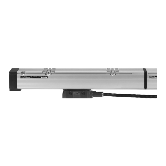
HEIDENHAIN LB 302 Montageanleitung
Vorschau ausblenden
Andere Handbücher für LB 302:
- Montageanleitung (24 Seiten) ,
- Montageanleitung (44 Seiten) ,
- Austauschanleitung (14 Seiten)

Verwandte Anleitungen für HEIDENHAIN LB 302


Inhaltszusammenfassung für HEIDENHAIN LB 302
- Seite 1 Montageanleitung Mounting Instructions LB 302 LB 382 mehrteilig Multi-Section 6/2004...
-
Seite 2: Inhaltsverzeichnis
8 Mounting Procedure Montage Mounting 10 Kabelausgang verlegen 10 Changing the Cable Outlet 11 Referenzmarken-Lage LB 302/LB 382 11 Reference Mark Position LB 302/LB 382 12 Abmessungen 12 Dimensions 14 Montage-Toleranzen 14 Mounting Tolerances 15 Befestigung der Gehäuseteilstücke 15 Mounting the Housing Sections 19 Laufbänder einziehen... - Seite 3 Warnhinweise Warnings Maße in mm Dimensions in mm...
-
Seite 4: Komponenten
Komponenten Components Separat bestellen: c Anschlusskabel Order separately: c Connecting cable a Abtasteinheit d Teilesatz a Scanning unit d Parts kit b Gehäuse-Teilstücke b Housing sections... - Seite 5 T1 = Typenschild T1 = ID label a) Adapterkabel a) Adapter cable b) dazugehöriges Verlängerungs- b) Matching extension cable kabel...
- Seite 6 Lieferumfang/Teilesatz Items Supplied/Parts Kit M Maßband (Messlänge ML) mit Typenschild T2 M Scale tape (measuring length ML) with ID label T2 Dichtlippe [2 x (ML + 1 m)] Sealing lip [2 x (ML + 1 m (3.3 ft))] E1 Endstück mit Klemmvorrichtung (auch spiegelbildlich lieferbar) E1 End section with clamping device (also available mirror-imaged) E2 Endstück mit Spannvorrichtung (auch spiegelbildlich lieferbar) E2 End section with tensioning device (also available mirror-imaged)
- Seite 7 Sealing lip grease Referenzmarkenschieber Referenzmarkenblende Reference mark slider Ref. mark selector plate O Dichtlippen-Klemmstück Stopfen O Sealing lip clamp Plug Distanzstück RM Referenzmarkenschild Spacer RM Reference mark label Montagehilfe Mounting aid 1) bei LB 302/LB 382 1) for LB 302/LB 382...
-
Seite 8: Hinweise Zur Montage
Hinweise zur Montage Mounting Procedure Anbauort so wählen, dass die Choose a mounting position to Bei vertikalem Anbau ohne Druck- When mounting vertically, Abtasteinheit auf keinen Fall an ensure that the scanning unit luft-Anschluss die Drainage- remove the drain screw if die Gehäusedeckel stoßen kann. - Seite 9 Während der Montage darauf Be sure that no contamination Teilungsseite des Maßbandes Do not touch the graduation side achten, dass keine Verunreini- enters the housing while you are nicht berühren. of the scale tape. gungen in das Maßstabsgehäuse mounting the scale. Maßband nicht knicken.
-
Seite 10: Kabelausgang Verlegen
Kabelausgang verlegen Changing the Cable Outlet Elektronik vor elektrostatischen Protect the electronics from accu- Deckel und ggf. Adapterkabel Detach the cover and (if Aufladungen schützen. Geerdetes mulating electrostatic charge. abschrauben. necessary) the adapter cables. Armgelenkband verwenden! A grounded bracelet can ensure protection during handling. -
Seite 11: Referenzmarken-Lage Lb 302/Lb 382
Referenzmarken-Lage LB 302/LB 382 Reference Mark Position LB 302/LB 382 An jedem Befestigungsloch und A reference mark can be selected Die erste bzw. letzte mögliche The first (or last) possible refer- davon im Abstand von n x 50 mm at any mounting hole and at... - Seite 12 = Referenzmarken-Lage r = Reference mark position F = Maschinenführung F = Machine guideway k = Kundenseitige Anschlussmaße k = Required mating LB 302/LB 382 LB 302/LB 382 d = Druckluftanschluss c = Referenzmarken-Lage c = Reference mark position dimensions g = Gehäuseteilstück-Längen...
- Seite 13 = Referenzmarken-Lage r = Reference mark position F = Maschinenführung F = Machine guideway k = Kundenseitige Anschlussmaße k = Required mating LB 302/LB 382 LB 302/LB 382 d = Druckluftanschluss c = Referenzmarken-Lage c = Reference mark position dimensions g = Gehäuseteilstück-Längen...
-
Seite 14: Montage-Toleranzen
Montage-Toleranzen Mounting Tolerances Montage-Möglichkeiten und Anbautoleranzen Mounting possibilities and tolerances = Maschinenführung F = machine guideway k = Kundenseitige Anschlussmaße k = Required mating dimensions * im Bereich eines Gehäusestoßes (± 50 mm). * Near a housing joint (± 50 mm) Waagerechter Anbau ist möglich. -
Seite 15: Befestigung Der Gehäuseteilstücke
Befestigung der Gehäuseteilstücke Mounting the Housing Sections Die Anbauflächen müssen lackfrei The mounting surfaces must be Bohrungen, Gewinde und Be- Threaded mounting holes and sein. clean and free of paint. festigungsschrauben. mounting screws. Befestigungsmöglichkeit am Mounting possibility on the cover Gehäusedeckel von Endstück ent- Remove end cap from end Deckel der Abtasteinheit. - Seite 16 Befestigung der Gehäuseteilstücke Mounting the Housing Sections Falls nicht schon vorhanden: Drill and tap mounting holes on Endstück zur Maschinenführung F Align end section to the machine Befestigungsgewinde an der Ma- the machine (if not already ausrichten und anschrauben guideway and screw down schine anbringen.
- Seite 17 Befestigung der Gehäuseteilstücke Mounting the Housing Sections Nächstes Gehäuseteilstück ansetzen, ausrichten und ggf. Bohrungen Place the next housing section on the machine and align. Mark holes ankörnen. Zwischen den Gehäusestücken Spalt b einhalten. Dazu rotes with a center punch if necessary. Use red spacer Z (small parts) to Distanzstück Z (Kleinteile) verwenden.
- Seite 18 Befestigung der Gehäuseteilstücke Mounting the Housing Sections Gehäusedeckel entfernen. Detach end cap and cover Spanneinrichtung herausnehmen. Pull out the tensioning device. Abdeckplatte Q abschrauben. plate Q. Anschlagplatte K heraus- Slide off stop plate K . Attach the Schraube S lösen. Remove screw S schieben.
-
Seite 19: Laufbänder Einziehen
Laufbänder einziehen Inserting the Bearing Strips Die Laufbänder können mit dem The bearing strips can be pulled in Haken des Einzieh-Werkzeugs in Place the hook of scale tape Einzieh-Werkzeug E eingezogen with scale tape puller E die benötigte Position einsetzen. puller E in the required position. -
Seite 20: Hinweise Zur Maßbandmontage
Hinweise zur Maßbandmontage Mounting the Scale Tape Teilung des Maßbandes mit fus- Clean the graduation surface with Verkürzungsfaktor V und Serien- Write down the shortening factor selfreiem Tuch und destilliertem a lint-free cloth and distilled spirit nummer des Maßbandes auf and the scale-tape serial Spiritus oder Isopropylalkohol or isopropyl alcohol. - Seite 21 Maßband einziehen, Maßband befestigen Inserting and Securing the Scale Tape Teilung nach unten Graduation facing downward Einzieh-Werkzeug E einfädeln, Insert scale tape puller E into Maßband einschieben. Now pull the tape into the Maßband einhängen. the housing and hook the tape Darauf achten, dass das Maßband housing by sliding the puller.
- Seite 22 Maßband befestigen Securing the Scale Tape Klemmschrauben S aus Maß- Unscrew clamping screws S Maßband über die beiden Loosely affix the scale tape at the bandhalter K herausschrauben. from scale tape holder K . Secure Bohrungen mit den Klemm- two holes with clamping screws mit Schrauben S anschrau- with screws S...
- Seite 23 Maßband befestigen Securing the Scale Tape Klemmschrauben S fest anzie- Tighten clamping screws S Maßband anschließend mit der Then, loosen the scale tape by hen (ca. 1.5 Nm). (approx. 1.5 Nm). Korrekturschraube S 11 revolutions of the tensioning Darauf achten, dass 2 Nm nicht Note: do not exceed 2 Nm 11 Umdrehungen lösen.
-
Seite 24: Dichtlippen Einziehen
Dichtlippen einziehen Inserting the Sealing Lips Dichtlippe halbieren und Solllänge Cut the sealing lip in half and Auf richtige Lage der Dichtlippen Ensure that the sealing lips are [= (ML + 226 mm) x 0.99] mark the nominal length achten. positioned correctly. - Seite 25 Dichtlippen stehen am Endstück E2 um 1 mm heraus. Dichtlippen am The sealing lips jut out at the end section E2 by 1 mm. Starting at end Endstück E1 ca. 200-300 mm aufstellen, danach vom Endstück E2 über section E1, orient the lips outward for approx. 200-300 mm, then from die gesamte Länge.
-
Seite 26: Dichtlippen Befestigen (Endstück E2)
Dichtlippen befestigen (Endstück E2) Securing the Sealing Lips (End Section E2) Anschlagplatte K am Endstück, Slide stop plate K onto end Gehäusedeckel mit 3 Schrauben Secure end cap with 3 screws an dem die Maßband-Spann- section (the end section with the M3 x 16 DIN 7985 befesti- M3 x 16 ISO 7045 (1 Nm). -
Seite 27: Abtasteinheit Einsetzen
Abtasteinheit einsetzen Installing the Scanning Unit Abtasteinheit vorsichtig einsetzen Carefully insert the scanning unit und lose anschrauben. and screw down loosely. Abtasteinheit ausrichten, entweder Align the scanning unit, using either I mit Transportsicherung oder II Fühlerlehre. I the shipping brace, or II the feeler gauge. Danach Befestigungsschrauben festziehen (M6: 8 Nm;... -
Seite 28: Mounting Tolerances
Dichtlippen befestigen (Endstück E1) Securing the Sealing Lips (End Section E1) Anbautoleranzen über die Check the mounting tolerances Dichtlippen am Endstück so- Pull out the sealing lips at end gesamte Messlänge überprüfen. over the entire measuring length. weit herausziehen, dass die Mar- section so that the marking kierung um 1 mm heraussteht. -
Seite 29: Final Steps
Abschließende Arbeiten Final Steps Elektrischer Widerstand zwischen Check the shielding by measuring LB an einer HEIDENHAIN Connect the encoder to a Steckergehäuse und Maßstabs- the resistance between connector Messwertanzeige anschließen HEIDENHAIN display unit and gehäuse: housing and scale. und Funktion über gesamten check for proper function over the −... -
Seite 30: Tensioning The Scale Tape
Maßband spannen Tensioning the Scale Tape Abtasteinheit soweit wie möglich Slide the scanning unit as far as Stopfen P vorsichtig entfernen. Carefully remove the plug P in Richtung Endstück fahren. possible toward the end. Reset Korrekturschraube S soweit Tighten the tape tensioning screw Messwertanzeige nullen. - Seite 31 Maßband um den vorher Increase the tape tension until the Nach dem Spannen die Klemm- Now tighten clamping screws S berechneten Wert spannen. display shows the value schraube S anziehen (2 Nm). (2 Nm). calculated before. Replace plug P Verschlussstopfen P wieder ein- .
-
Seite 32: Linear Error Compensation
Lineare Fehlerkorrektur Linear Error Compensation Eine lineare Fehlerkorrektur A linear error compensation of Vergleichsmesssystem, z. B. Set up a comparator system (such über die gesamte Messlänge up to ± 100 µm can be applied to Laserinterferometer, in der Werk- as a laser interferometer) in the kann bis ±... - Seite 33 Deckel Q und Stopfen P ent- Remove cover Q and plug P Korrekturwert K berechnen: Calculate compensation value K: fernen und Schraube S lösen. Slacken screw S Abstand X messen, Längen- measure distance X and multiply korrekturwert L (bestimmt aus with linear compensation value L Vermessung der Maschine).
-
Seite 34: Protective Measures
Schutzmaßnahmen Protective Measures Bei größerer Verschmutzungs- If there is significant danger of Druckluft: 1 bar nur über Anschluss- Compressed air: 14.5 psi only via gefahr empfiehlt sich eine contamination, fit a protective stück. Nur saubere und trockene connecting piece. zusätzliche Abdeckung mit cover over the encoder with a Druckluft verwenden. -
Seite 35: Mechanical Data
LB 302/LB 382 alle 50 mm, durch Blenden auswählbar LB 302/LB 382 Every 50 mm, selectable with plates LB 302 C/LB 382 C abstandscodiert mit 2000 x P LB 302 C/LB 382 C Distance-coded with 2000 x P Maximale Verfahr- 120 m/min Max. -
Seite 36: Lb 302/Lb 302C
Housing Außenschirm Innenschirm Ext. shield Int. shield – – – grün gelb blau grau rosa braun weiß weiß/braun Green Yellow Blue Gray Pink Brown White White/Brown EN 50 178/4.98; 5.2.9.5 IEC 364-4-41: 1992; 411(PELV/SELV) (siehe, see HEIDENHAIN D 231 929) -
Seite 37: Electrical Data
Elektrische Kennwerte LB 302/LB 302 C Electrical Data LB 302/LB 302 C Spannungsversorgung 5 V ± 5 %/100 mA (ohne Last) Power supply 5 V ± 5 %/100 mA (with no load) Ausgangssignale Output signals Inkrementalsignale 2 annähernd sinusförmige Signale I... -
Seite 38: Lb 382/Lb 382C
Green Green EN 50 178/4.98; 5.2.9.5 IEC 364-4-41: 1992; 411(PELV/SELV) (siehe, see HEIDENHAIN D 231 929) Die Sensorleitung ist intern mit der Versorgungsleitung verbunden. The sensor line is internally connected to the supply line. Schirm liegt auf Gehäuse. Shield is on housing. - Seite 39 Elektrische Kennwerte LB 382/LB 382 C Electrical Data LB 382/LB 382 C Spannungsversorgung 5 V ± 5 %/150 mA (mit Abschlusswider- Power supply 5 V ± 5 %/150 mA (with terminating stand Z = 120 −) resistor Z = 120 −...
- Seite 40 Ve 06 324 263-04 · 10 · 9/2007 · E · Printed in Germany · Änderungen vorbehalten · Subject to change without notice...