Inhaltsverzeichnis
Werbung
Verfügbare Sprachen
Verfügbare Sprachen
Quicklinks
Ablufttrockner | Mehrfamilienhaus und Gewerbe
Sèche-linge à sortie d'air | Immeuble collectif et usage
professionnel
Asciugatrice con scarico diretto dell'aria | Case plurifamiliari
e industria
Exhaust-air dryer | Apartment buildings and professional uses
Aufstellanleitung
Notice d'installation
Istruzioni per l'installazione
Installation instructions
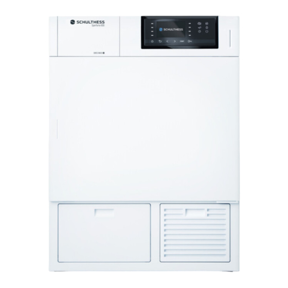
WT 14 MFH A
Werbung
Inhaltsverzeichnis

Verwandte Anleitungen für Schulthess WT 14 MFH A


Inhaltszusammenfassung für Schulthess WT 14 MFH A
- Seite 1 Sèche-linge à sortie d’air | Immeuble collectif et usage professionnel Asciugatrice con scarico diretto dell’aria | Case plurifamiliari e industria Exhaust-air dryer | Apartment buildings and professional uses Aufstellanleitung Notice d’installation Istruzioni per l’installazione Installation instructions WT 14 MFH A...
- Seite 2 Symbole Lesen Sie die Anleitungen. Warnhinweise sind mit einem Warndreieck gekennzeichnet. Es wird angegeben, wie die Gefahr vermieden werden kann. Signalwörter kennzeichnen die Schwere der Gefahr, die auftritt, wenn sie nicht vermieden wird. Warnung bedeutet, dass Personen schäden, unter Umständen auch lebens gefährliche Verletzungen auftreten können.
-
Seite 3: Sicherheit Und Schutzmassnahmen
Sicherheit und Schutzmassnahmen Beachten Sie beim Aufstellen Verlegen Sie Schläuche und ► und Anschliessen des Gerätes die Kabel so, dass man nicht folgenden Sicherheitshinweise, darüber stolpert. Warnungen, allgemeinen Hinweise Kinder können sich beim Spielen wie auch eventuelle besondere in Verpackungsteile oder Folien ein Vorschriften des zuständigen wickeln oder sich diese über den Wasser... -
Seite 4: Gerät Aufstellen
Gerät aufstellen Die Belüftungsöffnungen im ► Gehäuseboden dürfen nicht durch Teppichboden verstopft werden. Hinweis Die Betriebstemperatur des ► Kleine geschlossene Räume ohne Gerätes beträgt 5 bis 35 °C. Be und Entlüftungsmöglichkeit sind nicht geeignet als Aufstellort. Warnung Erstickungsgefahr! Der Trockner arbeitet nach dem Abluft Am Aufstellort und in den be... - Seite 5 Aufstellfläche Um die Standsicherheit des Gerätes zu gewährleisten, muss die Aufstellfläche fest, eben und trocken sein. Weiche Bodenbeläge, z.B. Teppichböden oder Beläge mit Schaumstoffrücken, sind als Untergrund nicht geeignet. Das Lüftungsgitter unterhalb der Tür darf nicht verdeckt werden. Halten Sie die Umgebung des Gerätes ►...
-
Seite 6: Wasch-Trocken-Säule
Wasch-Trocken-Säule Abluftöffnungen Um Platz zu sparen, kann der Wäsche Die Abluftleitung kann an der Rück trockner auf eine Waschmaschine seite oder an den Seitenwänden des gestellt werden (WaschTrocken Säule). Trockners angeschlossen werden. Der Trockner muss dabei mit einem Im Auslieferungszustand sind die Turm... - Seite 7 Rohrbogen anschliessen Hinweis Im Lieferumfang enthalten ist ein Rohr bogen mit separatem Dichtungsring, Verwenden Sie feuchtigkeits und ► Klemmring und vier Schrauben. wärmebeständige (bis 80 °C) Materia lien Druckverlust Beschaffenheit und Länge der Abluft leitung können den Durchfluss der Abluft erschweren, insbesondere wenn Knie stücke oder Rohrbögen mit engem Radius verwendet werden.
-
Seite 8: Abluftleitung Installieren
Innendurchmesser › 100 mm Hinweis Wird beim Planen eines Anschlusses Beachten Sie beim Installieren der mit Rohr Innendurchmesser 100 mm Abluftleitung folgende Punkte, um ein Gesamtdruckverlust von mehr als eine optimale Leistung des Trockners 150 errechnet, besteht die Möglichkeit, zu erhalten: über das Vergrössern des RohrInnen... - Seite 9 Einzelwerte zum Ermitteln des gesamten Druckverlusts (max. 150 ) Gewelltes Glattes Rohr Rohr Gerades Stück je 1 m Länge Rohrbogen Biegeradius R = 100 mm Biegeradius R = 200 mm TeleskopMauerkasten mit Gitter Druckverlust der Abluftleitung berechnen Glattes Rohr Innendurchmesser ø = 100 mm Rohrbogen Gerade Stücke (total 3 m) Rohrbogen...
-
Seite 10: Elektrischer Anschluss
Elektrischer Anschluss Abluft über einen Mauer kasten in ein Kamin oder einen Lüftungs- schacht führen Soll die Abluftleitung an einen feuchtig Hinweis keitsisolierten Lüftungs schacht ange Der Anschluss an die Strom versorgung schlossen werden, ist der zuständige muss durch eine Fachperson ausge Kaminfeger zu verstän digen bzw. - Seite 11 Netzleitung 400 V 3N ~ Das Gerät wird mit einer 150 cm langen 5adrigen Netz leitung zum Anschluss an 3PhasenWechselstrom mit Neutral L2 L1 N leiter geliefert. Sicherungen und Schalter werden nicht mitgeliefert. Warnung L3 L2 L1 N Gefahr von Stromschlag oder Brand! Verwenden Sie keine Verlängerungs...
- Seite 12 400 V 2 N ~ Netzanschluss reduziert L2 L1 N L3 L2 L1 N Heizung 4,0 kW Motor 0,4 kW Sicherung 10 AT 230 V 1 N ~ Netzanschluss reduziert L2 L1 N L1 mit L3 verbinden L2 abschneiden L3 L2 L1 N Heizung 3,3 kW Motor...
- Seite 13 Notizen DE 13...
- Seite 14 Symboles Lisez les instructions. Les avertissements de sécurité sont précédés d’un triangle de signalisation. Il est indiqué comment éviter le danger. Les avertissements caractérisent la gravité du danger qui survient si celuici n’est pas évité. Avertissement indique que de graves dommages corporels, voir même un danger de mort peuvent survenir.
- Seite 15 Sécurité et mesures de protection Respectez les conseils de sécurité, En cas de pose non conforme des consignes et remarques générales tuyaux et câbles d’alimentation, il lors de l’installation et du raccor existe un risque de trébuchement de ment de l’appareil ainsi que les et de blessure.
-
Seite 16: Installer L'appareil
Installer l’appareil Les ouvertures de ventilation au ► fond du boîtier ne doivent pas être colmatées par la moquette. La température d’exploitation de ► Avertissement l’appareil est de 5 à 35 °C. Les petites pièces fermées sans aéra tion ne conviennent pas à l’installation Avertissement d’un sèchelinge. - Seite 17 Emplacement d’installation Afin de garantir la stabilité de l’appa reil, sa surface d’installation devra être fixe, plane et sec. Les revêtements de sol souples tels que moquettes ou matériaux à dos en produit alvéolaire ne conviennent pas à cet effet. Ne pas couvrir la grille d’aération visible sur l’avant de l’appareil, en dessous de la porte.
- Seite 18 Orifices de ventilation La conduite d’évacuation de l’air peut être raccordée derrière ou sur les côtés du sèchelinge. L’appareil est livré avec les deux orifices de ventilation latéraux couverts. Variante de raccordement latérale Colonne de lavage et séchage Afin de gagner de la place, vous pouvez installer votre sèchelinge sur le lave...
- Seite 19 Note Utilisez des matériaux résistants à ► l’humidité et à la chaleur (jusqu’à 80 °C). Pertes de pression La nature et la longueur de la conduite d’évacuation d’air, en particulier dans Collez le joint sur la bride du tuyau. ► les coudes ou les pièces courbes à...
- Seite 20 Diamètre intérieur du tuyau Note › 100 mm Lors de l’installation de la conduite Si une perte de pression totale de plus d’évacuation de l’air, tenez compte des de 150 est calculée lors de la planifica points suivants pour assurer les per tion d’un raccordement avec diamètre formances optimales du sèchelinge: intérieur du tuyau de 100 mm, il est...
- Seite 21 Valeurs individuelles pour déterminer la perte de pression totale (max. 150 ) Tuyau lisse Tuyau ondulé Pièce rectiligne 1 m de long chaque fois Tuyau courbé Rayon de courbure R = 100 mm Rayon de courbure R = 200 mm Coffret mural télescopique avec grille Calculer la perte de pression de la conduite d’évacuation de l’air...
- Seite 22 Evacuer l’air par un coffret mural Possibilité d’écoulement pour l’eau dans une cheminée ou un puits de de condensation ventilation A l’emplacement le plus bas de la En cas de raccordement à un puits conduite d’évacuation d’air, on recom d’aération isolé contre l’humidité, il mande de placer un «collecteur d’eau faut informer le ramoneur responsable de condensation»...
-
Seite 23: Raccordement Électrique
Raccordement électrique Avertissement Risque de choc électrique et d’incendie! Note N’utiliser ni rallonges, ni blocs multi Le branchement de l’appareil au réseau prises ni programmateurs horaires doit être effectué par un technicien mobiles intercalés sur la prise secteur. spécialisé. L’appareil ne doit pas être branché par l’intermédiaire d’un dispositif de Raccordement électrique souple selon commutation externe, allumant et... - Seite 24 400 V 3N ~ 400 V 2 N ~ Réseau électrique réduit L2 L1 N L2 L1 N couper L3 L3 L2 L1 N L3 L2 L1 N Chauffage 5,5 kW Chauffage 4,0 kW Moteur 0,4 kW Moteur 0,4 kW Fusible 10 AT Fusible...
- Seite 25 Notes FR 25...
- Seite 26 Simboli Leggere le istruzioni. Le avvertenze sono contrassegnate da un triangolo di avvertimento. Indicano come evitare il pericolo incombente. Le parole di segnalazione indicano la gravità del pericolo che può veri ficarsi se non viene evitato questo pericolo. Avvertenza significa che possono verificarsi danni a persone e lesioni mortali.
- Seite 27 Sicurezza e misure preventive Per l’installazione ed il collega Accertarsi che i tubi flessibili e i cavi mento dell’apparecchio si prega di di alimentazione siano installati osservare le seguenti informazio correttamente per evitare rischi di ni di sicurezza, le avvertenze, le inciampo e di ferimento.
-
Seite 28: Installazione Dell'apparecchio
Installazione dell’apparecchio Non montare l’apparecchio die ► tro a una porta chiudibile, a una porta scorrevole o a una porta, la cui cerniera è posizionata di Avviso fronte alla cerniera dell’asciuga Gli ambienti piccoli e chiusi che non trice in modo tale da impedire offrono la possibilità... - Seite 29 Superficie di installazione Attenersi alle misure dell’apparecchio Per garantire la stabilità dell’apparec chio durante la fase di centrifugazione, La distanza minima obbligatoria tra la superficie su cui poggia l’apparecchio l’apparecchio e la parete, oppure da un deve essere solida, piana e asciutta. altro apparecchio, deve essere di 1 cm.
- Seite 30 Uscite di scarico dell’aria La tubazione di scarico ariavapore può essere collegata al retro o alle pareti laterali dell’apparecchio. Alla consegna dell’apparecchio le due uscite di scarico laterali sono coperte. Variante con collegamento laterale Colonna lava-asciuga Per risparmiare spazio, è possibile installare l’asciugatrice sopra ad una lavatrice (colonna lavaasciuga).
- Seite 31 Collegare il raccordo a gomito Avviso Nelle dotazioni è incluso un raccordo a gomito con anello di guarnizione sepa Il materiale deve essere resistente ► rato, anello di bloccaggio e quattro viti. all’umidità e al calore fino ad 80 °C. Perdite di pressione Struttura e lunghezza del tubo di scarico possono ostacolare il flusso dell’aria di...
- Seite 32 Diametro interno › 100 mm Avviso Qualora si pianifichi un collegamento Osservare i punti seguenti quando con tubo di 100 mm di diametro interno si installa il tubo dell’aria di scarico, e si calcoli una perdita complessiva di affinché l’asciugatrice funzioni ottima pressione di oltre 150, vi è...
- Seite 33 Dati per determinare la perdita di pressione totale (max. 150 ) Tubo liscio Tubo ondulato Tratto rettilineo per 1 m di lunghezza Arco Raggio di curvatura R = 100 mm Raggio di curvatura R = 200 mm Cassetta telescopica a muro con griglia Calcolare la perdita di pressione della tubazione di scarico Tubo liscio...
-
Seite 34: Collegamento Elettrico
Collegamento elettrico Uscita della tubazione in un camino attraverso una cassetta a muro o un pozzetto di ventilazione In caso di collegamento ad un pozzetto Avviso di ventilazione isolato dall’umidità deve L’allacciamento elettrico deve essere essere informato lo spazzacamino, effettuato solamente da un tecnico o il competente locale Ispettorato specializzato. - Seite 35 Cavo di rete 400 V 3N ~ L’apparecchio viene fornito con cavo di rete a cinque conduttori (lunghezza: 150 cm) per il collegamento alla cor L2 L1 N rente alternata trifase con conduttore di neutro). Le valvole di sicurezza e gli interruttori non fanno parte della fornitura.
- Seite 36 400 V 2 N ~ Allacciamento rete ridotto L2 L1 N tagliare L3 L3 L2 L1 N Riscaldamento 4,0 kW Motore 0,4 kW Valvola di sicurezza 10 AT 230 V 1 N ~ Allacciamento rete ridotto L2 L1 N attagare L1 con L3 tagliare L2 L3 L2 L1 N Riscaldamento...
- Seite 37 Note IT 37...
- Seite 38 Symbols Please read the instructions. Warnings are marked with a warning triangle. The text gives information how a dangerous situation can be avoided. Signal words indicate the severity of the danger, if not avoided. Warning means that possible personal injuries, and potentially lifethreat ening injuries may occur.
- Seite 39 Safety and safety measures When installing and connecting Inexpert installation of hoses the appliance, the following safety and power cables may cause trip instructions, warnings, general hazards and danger of injury. instructions and any possible Lay hoses and cables in such a ►...
-
Seite 40: Installing The Appliance
Installing the appliance The ventilation openings in the ► housing floor must not be ob structed by carpeting. Operating temperature of the ► Notice appliance is 5 to 35 °C. Do not install the dryer in an enclosed area or in any area without fresh air Warning circulation. - Seite 41 Installation area Keep machine dimensions in mind In order to ensure the stability of The minimum distance between the the appliance during spin drying, the machine and the wall or possibly an installation area must be firm and level. other machine is 1 cm. Soft floor coverings, e.g.
- Seite 42 Exhaust vents The connection possibilities for an exhaust air duct are located at the rear panel and on both sides of the appliance. When delivered, the two lateral exhaust openings are covered. Lateral connection variant Washer-Dryer tower In order to save space (installation space), you can place your dryer on top of a washing machine (washerdryer tower).
- Seite 43 Connecting the tube curve Pressure loss Included is a tube curve with a sep The nature and length of the exhaust arate sealing ring, clamping ring and air duct, in parti cular knee pieces or four screws. curves with small radii, impede the flow of air.
- Seite 44 Installing the exhaust duct Calculating the pressure loss Notice Depending on the structural situation, To ensure the minimum required air the exhaust air can be conducted in flow, the total pressure loss must not different ways to the outside: exceed the value of 150. •...
- Seite 45 Individual values for determining the total pressure loss (max. 150 ) Smooth Corrugated tubing tubing Straight piece each 1m long Bending radius R = 100 mm Tube curve Bending radius R = 200 mm Telescope wall box with grid Calculating the pressure loss of the exhaust air duct Smooth tubing Internal diameter ø...
-
Seite 46: Electrical Connection
Electrical connection Routing the exhaust air through a wall box into a fireplace or ventila- tion shaft In the case of a connection to a venti Notice lation shaft insulated against moisture, Connection of the appliance to the the responsible chimney sweep is to be power supply must be carried out by a informed and the approval of the local specialised electrician. - Seite 47 400 V 3N ~ Warning Risk of electric shock and risk of fire! L2 L1 N No extension cables, no multicoupling and no plugin, mobile time switches may be used. Do not use plugin, mobile timer switches. The machine may not be connected via an external switching L3 L2 L1 N mechanism, which regularly switches...
- Seite 48 400 V 2 N ~ Reduced mains power L2 L1 N cut off L3 L3 L2 L1 N Heating 4,0 kW Motor 0,4 kW Fuse 10 AT 230 V 1 N ~ Reduced mains power L2 L1 N connect L1 with L3 cut off L2 L3 L2 L1 N Heating...
- Seite 49 EN 49...
- Seite 50 Notes 50 EN...
- Seite 52 Traduzione dall‘ originale delle istruzioni per l’installazione Translation of the original installation instruction InstruktionsNr. 638 976.AA No. d’instruction No. d’istruzione Instruction no WT 14 MFH A 10 / 17 Printed in Switzerland / Subject to change without notice de / fr / it / en...