Herunterladen Inhalt Inhalt Diese Seite drucken
AERMEC PGD1 Bedienungsanleitung
Vorschau ausblenden Andere Handbücher für PGD1:

Werbung

Verfügbare Sprachen
  • DE

Verfügbare Sprachen

• Pannello remoto semplifi cato • Simplifi ed remote panel
• Console à distance simplifi ée • Vereinfachte Fernsteuerungstafel
• Panel remoto simplifi cado.
PGD1
IT
GB
FR
DE
ES
pag. 2
pag. 6
pag. 10
pag. 14
pag. 18
PGD1. 1102. 4804250 _00

Werbung

Inhaltsverzeichnis
loading

Inhaltszusammenfassung für AERMEC PGD1

  • Seite 1 • Pannello remoto semplifi cato • Simplifi ed remote panel • Console à distance simplifi ée • Vereinfachte Fernsteuerungstafel • Panel remoto simplifi cado. ● PGD1 pag. 2 pag. 6 pag. 10 pag. 14 pag. 18 PGD1. 1102. 4804250 _00...
  • Seite 2: Montaggio A Parete

    PGD1 display grafi co DESCRIZIONE: Il display grafi co pGD1 è un dispositivo elettronico, che consente la com- pleta gestione della grafi ca tramite la visualizzazione di icone e la gestione di font internazionali di due dimensioni: 5x7 e 11x15 pixel.
  • Seite 3: Segnalazione Guasti

    5) Collegare con il cavetto telefonico il terminale PGD1 alla scheda di derivazione N°2 sul connettore telefonico siglato “A”. 6) L’indirizzo di rete pLAN da assegnare al terminale PGD1 è 6 (dip 2 = ON e dip 3 = ON).
  • Seite 4: Caratteristiche Tecniche

    Retroilluminazione: LED verdi (comandabile da “software rispettive morsettiere a vite con del cavo AWG20 / 22, collegare il applicativo”) PGD1 alla scheda dI derivazione Risoluzione in grafi ca: 120x32 pixel Modi testo: 4 righe x 20 colonne (font 5x7 e 11x15...
  • Seite 5 50 < D < 500 : CON ALIMENTAZIONE Morsetto Oin.conn.telefonico Funzione conn.a vite Terra (calza del cavo schermato +VRL = 18 - 30 VDC Rx-/Tx- Rx+/+ +VRL= 18 - 30 VDC J14 e J15 in posizione 1-2: i tre connettori telefonici (A, B e C) ed il con- nettore a vite (SC) sono posti in parallelo.
  • Seite 6: Wall Mounting

    PGD1 graphical display DESCRIPTION: The pGD1 graphical display is an electronic device, which allows the complete management of the graphics via the display of icons and the management of international fonts with two dimensions: 5x7 and 11x15 pixel. WALL MOUNTING The wall-mounting of the terminal envisions the initial fi...
  • Seite 7: Electric Connections

    5) Use the telephone cable to connect the PGD1 terminal to bypass board N°2 on the telephone connector marked “A”. 6) The pLAN network address to be assigned to the PGD1 terminal is 6 (dip 2 = ON and dip 3 = ON).
  • Seite 8: Technical Features

    5) Connect the two bypass boards to each other connecting to the Graphical resolution: 120x32 pixel respective screw terminal boards with the AWG20/22 cable. Connect the PGD1 to the bypass board. Text modes: 4 lines x 20 columns (font 5x7 and 11x15 pixel)
  • Seite 9 PGD1 graphical display 50 < D < 500 : WITH POWER SUPPLY Screw conn. Oin. telephone Function clamp connection Earth (shielded cable braid) +VRL = 18 - 30 VDC Rx-/Tx- Rx+/+ +VRL = 18 - 30 VDC J14 and J15 in position 1-2: the three telephone connectors (A, B and UNITÁ...
  • Seite 10: Montage Mural

    PGD1 écran graphique DESCRIPTION: L'écran graphique pGD1 est un dispositif électronique qui permet la ges- tion complète de la graphique à travers l'affi chage d'icônes et la gestion de polices internationales en deux dimensions: 5x7 et 11x15 pixel. MONTAGE MURAL Le montage mural du terminal requiert la fi...
  • Seite 11 5) A l'aide du câble téléphonique, brancher le terminal PGD1 à la carte de dériva- tion N°2 sur le connecteur téléphonique portant le sigle “A”. 6) L'adresse de réseau pLAN à attribuer au terminal PGD1 est 6 (dip 2 = ON et dip 3 (Fig. 9) = ON).
  • Seite 12: Caracteristiques Techniques

    PGD1 écran graphique CARACTERISTIQUES TECHNIQUES : 4) il est nécessaire de positionner les bretelles J14 et J15 des cartes de Ecran dérivation sur la position 2-3. Type: graphique FSTN Rétro-éclairage: LEDs vertes (pilotée depuis “logiciel d'application”) 5) Brancher les deux cartes de dérivation entre elles en se connectant Résolution graphique:...
  • Seite 13 PGD1 écran graphique 50 < D < 500 : AVEC ALIMENTATION Borne connec- Oin. connecteur Fonction teur à vis téléphonique Terre (gaine du câble blindé) +VRL = 18 - 30 VDC Rx-/Tx- Rx+/+ +VRL = 18 - 30 VDC J14 et J15 en position 1-2: les trois connecteurs téléphoniques (A, B et UNITÁ...
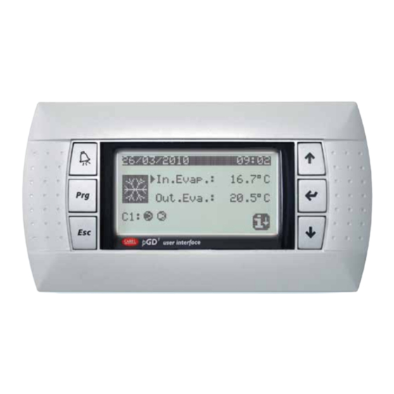
  • Seite 14 PGD1 Grafi sches Display BESCHREIBUNG: Das grafi sche Display pGD1 ist ein elektronisches Gerät, mit dem die Grafi k vollständig mittels Anzeige von Symbolen und mit internationalen Schriftar- ten in zwei Größen gesteuert werden kann: 5x7 und 11x15 Pixel. WANDMONTAGE Die Wandmontage des Terminals sieht die vorherige Befestigung des Hin- tergehäuses A (Abb.
  • Seite 15: Störungsmeldungen

    4) Sicherstellen, dass die Jumper J14 und J15 der Anschlusskarten sich in der Position 1-2 befi nden. 5) Mit dem Telefonkabel das Terminal PGD1 an die Anschlusskarte Nr. 2 am mit "A" markierten Telefonsteckverbinder anschließen. 6) Dem Terminal PGD1 ist die pLAN-Netzwerkadresse 6 zuzuweisen (Dip 2 = ON, Dip (Abb.
  • Seite 16: Technische Daten

    Grafi sch, FSTN Hintergrundbeleuchtung: Grüne LEDs (steuerbar über "Anwen- 5) Beide Anschlusskarten miteinander an den jeweiligen Schraubklem- dungssoftware") men mit dem Kabel AWG20 / 22 verbinden und den PGD1 an die Grafi kaufl ösung: 120x32 Pixel Anschlusskarte anschließen. Textmodi: 4 Zeilen x 20 Spalten (Schriftarten 5x7...
  • Seite 17 PGD1 Grafi sches Display 50 < D < 500: MIT STROMVERSORGUNG Schraubklemme Oin.Telefon- Funktion Verbinder Erde (Umfl echtung des geschirmten Kabels) +VRL = 18 - 30 VDC Rx-/Tx- Rx+/+ +VRL = 18 - 30 VDC J14 und J15 in Position 1-2: Die 3 Telefon-Steckverbinder (A, B und C) UNITÁ...
  • Seite 18: Montaje En La Pared

    PGD1 visor gráfi co DESCRIPCIÓN: El visor gráfi co pGD1 es un dispositivo electrónico que permite una com- pleta administración de la gráfi ca a través de la visualización de íconos y la administración de fuentes internacionales en dos dimensiones: 5x7 y 11x15 píxeles.
  • Seite 19: Conexiones Eléctricas

    5) Con el cable telefónico, conecte el terminal PGD1 con la tarjeta de derivación Nº 2 del conector telefónico con la sigla "A". 6) La dirección de red pLAN que se debe asignar al terminal PGD1 es 6 (dip 2 = ON (Fig. 9) y dip 3 = ON).
  • Seite 20: Características Técnicas

    “software aplicativo”) respectivos borneros con tornillo con el cable AWG20 / 22, conecte el Resolución en gráfi ca: 120x32 píxeles PGD1 a la tarjeta de derivación Modos texto: 4 líneas x 20 columnas (fuente 5x7 y 11x15 píxeles) 2 líneas x 10 columnas (fuente 11x15 píxeles) o modos mixtos...
  • Seite 21: Panel De Conectores

    PGD1 visor gráfi co 50 < D < 500 : CON ALIMENTACIÓN Bornero con. Oin.con.telefónico Función con tornillo Tierra (cubierta del cable apantallado) +VRL = 18 - 30 VDC Rx-/Tx- Rx+/+ +VRL = 18 - 30 VDC J14 y J15 en posición 1-2: los tres conectores telefónicos (A, B y C) y el Unidades UNITÁ...
  • Seite 22 PGD1_4804250 _00...
  • Seite 23 Smaltimento del prodotto L’apparecchiatura (o il prodotto) deve essere oggetto di raccolta separata in conformità alle vigenti normative locali in materia di smaltimento. Disposal of the product The appliance (or the product) must be collected separately in compliance with the local Standards in force regarding disposal. Elimination du produit L'appareil (ou le produit) doit faire l'objet d'une collecte séparée conformément aux réglementations locales en vigueur en matière d’élimination des déchets.
  • Seite 24 The client (manufacturer, designer or installer of the equipment) is responsible for the installation phase of the product and guaranteeing that it achieves the envisioned results. Not carrying out this phase, requested / indicated by the instructions, can generate malfunctioning of the product and AERMEC can not be held responsible. The end client must use the product only in the mode described in the documents provided with the kit.

Inhaltsverzeichnis