Herunterladen Inhalt Inhalt Diese Seite drucken

Werbung

Verfügbare Sprachen
  • DE

Verfügbare Sprachen

  • DEUTSCH, seite 31
I 56- 3947- 202
DESCRIPTION
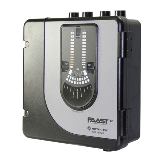
The LT NFXI-ASD Series is part of the Fire Alarm Aspiration
Sensing Technology
(FAAST) family. FAAST is an advanced
®
fire detection system for use where early warning and very early
warning are a requirement. The system continuously draws air
from the controlled environment through a series of sampling holes
to monitor the environment for smoke particulate.
The NFXI-ASD is the addressable version of the FAAST LT range,
communicating with the CIE (Fire Panel) via a proprietary loop
protocol. It is available in 3 different models:
NFXI-ASD11 - Has single channel capability with one laser smoke
sensor.
NFXI-ASD12 - Has single channel capability with two laser smoke
sensors in a common chamber for coincidence
detection.
NFXI-ASD22 - Has two channel capability with two laser smoke
sensors in separate chambers. (one sensor for
each channel).
This guide provides information for mounting and basic installation
using the unit's default factory settings. For more advanced information
please see the FAAST LT Advanced Setup and Control Guide.
SPECIFICATIONS
Electrical Characteristics
Voltage Range:
Supply Current:
1 Channel:
2 Channel:
Communication Loop Supply Voltage: 15 – 29 VDC (Loop current ≤
Communication Loop Standby Current: @ 24V: 900 µA max. (poll once
Module Isolator Characteristics
Maximum rated switching current
(under short circuit, Is max):
Maximum leakage current (IL max)
with the switch open (isolated state):
Maximum series impedance with
the switch closed (Zc max):
N200-102-00
FIRE ALARM ASPIRATION SENSING TECHNOLOGY
QUICK INSTALLATION GUIDE ADDRESSABLE FAAST LT
MODELS NFXI-ASD11, NFXI-ASD12, NFXI-ASD22
18.5 - 31.5 VDC
170mA (typical); 360mA (max) @
24 VDC 25
C (excluding sounders)
o
270mA (typical); 570mA (max) @
24 VDC 25
C (excluding sounders)
o
900mA)
every 5s)
0.9A @ ≤ 29V
15mA
190 m ohm at 15Vdc; 1A
50 mm
60 mm
110 mm
356 mm
Figure 1: Dimensions and Knock-Outs
Power Reset:
Configurable Input: Activation Time:
Relay Contact Ratings:
Environmental Ratings
Temperature:
Relative Humidity:
IP Rating:
Mechanical
Exterior Dimensions:
Wiring:
Maximum Single Pipe Length:
Maximum Branched Pipe Length:
Maximum Number of Holes
Pipe Spec (EN54-20 Compliance):
Outside Pipe Diameter:
Shipping Weight:
PARTS LIST
Description
FAAST LT unit
Mounting bracket
3-pin Terminal block
4-pin Terminal block
2-pin Terminal block
47 k-ohm EOL Resistor
USB Cable
Front Panel Labelling Pack
Wiring Diagram Label
Installation Kit CD
Quick Installation Guide
Aspirating Smoke Detectors supplied and installed within the
EU must conform to the EU Construction Products Regulation
(CPR) 305/2011 and the related European Product Standard EN
54-20. FAAST LT has been tested and certified to ensure that it
conforms to the necessary Standards, but strict adherence to this
instruction guide is advised to ensure that the installation meets
the requirements of the CPR.
1
E N G L I S H
®
50 mm
0.5s
2s (min)
2.0 A @ 30 VDC, 0.5A @ 30 VAC
-10°C to 55°C
10% to 93% (non-condensing)
65
See Figure 1
0.5 mm² to 2 mm² max
100m (Classes B & C) 80m (A)
160m (2 x 80m, Class C)
See Table 1A
to EN 61386
(Crush 1, Impact 1, Temp 31)
25mm (nom) or 27mm (nom)
6.5kg (inc sensors)
Quantity
1
1
6
1
3
2
1
1
1
1
1
Important Note
44 mm
56 mm
135 mm
I56-3947-202

Werbung

Inhaltsverzeichnis
loading

Inhaltszusammenfassung für Notifier NFXI-ASD11

  • Seite 1 10% to 93% (non-condensing) communicating with the CIE (Fire Panel) via a proprietary loop IP Rating: protocol. It is available in 3 different models: Mechanical NFXI-ASD11 - Has single channel capability with one laser smoke Exterior Dimensions: See Figure 1 sensor. Wiring: 0.5 mm²...
  • Seite 2: Physical Installation

    Warning The performance of this system is dependent upon the pipe network. Any extension or modification to the designed installation may cause improper operation. The operational effects of such changes need to be verified using the PipeIQ 2 design software. Figure 4: How to Knock Out Cable Gland Holes This equipment and all associated pipe work must be installed in...
  • Seite 3 Figure 7: Sequence (1 to 9) to Mount the Detector on the Bracket Pipe Hole Configuration Figure 8 below shows the pipe holes available on the unit. Each unit has 2 pipe holes per channel connected together like a T-Piece. 99 mm If using a 1 channel unit, holes 3 and 4 do not function.
  • Seite 4: Wiring Installation

    Exhaust Pipe Whenever the FAAST LT is installed outside the risk area, return of the exhaust air back into the protected area can reduce flow faults due to pressure difference. SAMPLING AREA SAMPLING AREA WIRING INSTALLATION Power, Alarm and Control Connections CHANNEL 1 FILTER CHANNEL 2 FILTER EARTH BAR...
  • Seite 5 Fitting the Terminal Blocks WARNING: Switching Inductive Loads To insert the terminal blocks into the unit use the following method: FAAST LT 1 Insert a corner of the block into the slot (see a). 2 Push the length of the block into the slot until the block ‘clicks’ into place, the 2 upper hooks on the block should be visible (see c).
  • Seite 6: External Reset

    SETTING THE ADDRESSES POWERING UP Using Default Settings Each aspiration channel uses loop communications to report its status information to the CIE (Fire Panel). As a factory default, 1. Connect a suitable 24VDC supply (complying with European the unit will report smoke alarm and sensor information at an Standard EN 54-4) to pins 1 and 2 on terminal block T1 (See associated sensor address and general alerts and faults on a Table 2)
  • Seite 7: Front Panel

    PREALARM SMOKE LEVEL MODULE 11b: NFXI-ASD12 1 Channel Detector (2 Sensors) POWER FAULT FAULT ALARM PREALARM 11a: NFXI-ASD11 1 Channel Detector (1 Sensor) SMOKE SMOKE LEVEL 1 LEVEL 2 MODULE 1 MODULE 2 POWER FAULT FAULT 11c: NFXI-ASD22 2 Channel Detector...
  • Seite 8 Table 4: Front Panel Indicators and Fault Descriptions INDICATOR ACTION WARNING OR TROUBLE COMMENT / ACTION CHANNEL 1/2 ALARM ON Red Channel is in alarm (relay is Default setting (Set by panel) set ON with no delay) 1 BLINK Green When sensor is polled Not when in alarm (Polled by panel)
  • Seite 9 PREALARM SMOKE Table 5: Front Panel Buttons LEVEL 2 INITIALIZATION BUTTON NORMAL Mode MAINTENANCE Mode RESET When pressed for 2 s, starts PASSWORD When pressed for 2 s latched alarms, faults and POWER PROCEDURE to enter Maintenance sounders (relays) are reset. Alarm controlled by panel. If FAULT mode.
  • Seite 10: Laser Safety Information

    Declaration of Performance Ref: Note: If replacing the filter, remove the foam gasket from the old NFXI-ASD11: DOP-ASP012 filter and place onto the new filter. When placing the new filter into NFXI-ASD12: DOP-ASP013 the slot, ensure that the gasket is correctly aligned.
  • Seite 11: Elenco Delle Parti

    È disponibile in 3 diversi modelli: Cablaggio: da 0,5 mm² a 2 mm² max NFXI-ASD11 - Ha un singolo canale a disposizione con un rivelatore Lunghezza massima tubo singolo: 100 m (Classi B e C) 80 m (Classe A)
  • Seite 12: Installazione Fisica

    Questa apparecchiatura e tutte le tubazioni associate devono essere installate in conformità a tutti i codici e alle normative pertinenti. INSTALLAZIONE FISICA Etichette per pannello anteriore Figura 4: come praticare i fori serracavo Il modello LT NFXI-ASD viene spedito senza etichette applicate sul pannello anteriore.
  • Seite 13 Tabella 1: fori sui tubi utilizzati per ogni modello FAAST LT MODELLO FORO SU TUBO DI FORO SU TUBO DI FAAST LT ASPIRAZIONE SCARICO NFXI-ASD11 1 e/o 2 NFXI-ASD12 1 e/o 2 NFXI-ASD22 Canale 1 - 1 e/o 2 Canale 2 – 3 e/o 4 Nota 1: i fori sui tubi non utilizzati devono essere tenuti sigillati.
  • Seite 14 Tubo di scarico Ogni volta che FAAST LT viene installato al di fuori della zona a rischio, il ritorno dell'aria di scarico nella zona protetta può ridurre i guasti di flusso dovuti alla differenza di pressione. AREA DI CAMPIONAMENTO AREA DI CAMPIONAMENTO INSTALLAZIONE DEL CABLAGGIO Collegamenti di alimentazione, allarme e controllo FILTRO CANALE 1...
  • Seite 15 Fissaggio morsettiere AVVERTENZA: Commutazione carichi induttivi Per inserire le morsettiere nell’unità utilizzare il seguente metodo: FAAST LT Inserire un angolo della morsettiera nella fessura (vedere a). Premere tutta la lunghezza della morsettiera nella fessura finché non scatta in posizione, i due ganci superiori sulla morsettiera devono essere visibili (vedere c).
  • Seite 16: Impostazione Degli Indirizzi

    IMPOSTAZIONE DEGLI INDIRIZZI ACCENSIONE Utilizzo delle impostazioni predefinite Ogni canale di aspirazione utilizza comunicazioni sul loop per segnalare informazioni sullo stato al CIE (pannello antincendio). Per 1. Collegare un'alimentazione a 24 VCC idonea (in conformità dello impostazione predefinita in fabbrica l'unità segnala informazioni sui standard europeo EN 54-4) ai terminali 1 e 2 sulla morsettiera T1 sensori e sugli allarmi all'indirizzo del sensore associato e avvisi e (vedere Tabella 2)
  • Seite 17: Pannello Anteriore

    LEVEL MODULE 11b: NFXI-ASD12 rivelatore a 1 canale (2 sensori) POWER FAULT FAULT ALARM PREALARM SMOKE 11a: NFXI-ASD11 rivelatore a 1 canale (1 sensore) SMOKE LEVEL 1 LEVEL 2 MODULE 1 MODULE 2 POWER FAULT FAULT 11c: NFXI-ASD22 rivelatore a 2 canali...
  • Seite 18 Tabella 4: indicatori del pannello anteriore e descrizioni dei guasti INDICATORE AZIONE AVVERTENZA O PROBLEMA COMMENTO/AZIONE ALLARME CANALE 1/2 ACCESO rosso Il canale è in allarme (relè Impostazione predefinita (Impostato da pannello) impostato su ON senza ritardo) 1 verde LAMPEGGIO verde Quando il sensore è...
  • Seite 19 PREALARM SMOKE Tabella 5: pulsanti del pannello anteriore LEVEL 2 PULSANTE INITIALIZATION Modalità NORMALE Modalità di MANUTENZIONE RESET Quando premuto per Premendo per 2 secondi vengono resettati allarmi con memoria, guasti e POWER 2 secondi, avvia la sirene (relè). Allarme controllato dal pannello. Se l'allarme persiste, FAULT PROCEDURA DI reimpostare immediatamente dopo il ripristino.
  • Seite 20: Connessione Usb

    Nota: In caso di sostituzione del filtro, rimuovere la guarnizione Dichiarazione delle prestazioni rif. espansa dal vecchio filtro e posizionarla sul nuovo filtro. Posizionando NFXI-ASD11: DOP-ASP012 il nuovo filtro nell'apposito spazio, assicurarsi che la guarnizione sia NFXI-ASD12: DOP-ASP013 correttamente allineata.
  • Seite 21: Especificaciones

    Longitud máxima de una única tubería: 100 m (Clases B y C) 80 m (Clase A) NFXI-ASD11: Capacidad de canal único y un sensor de humo con láser. Longitud máxima de tubería ramificada: 160 m (2 x 80 m, Clase C) NFXI-ASD12: Capacidad de canal único y dos sensores de humo...
  • Seite 22 Este equipo, junto con la canalización asociada, debe instalarse de conformidad con los códigos y reglamentaciones pertinentes. INSTALACIÓN FÍSICA Etiquetas del panel frontal LT NFXI-ASD no se entrega con las etiquetas del panel frontal ya colocadas. De este modo, el instalador puede elegir el idioma correspondiente para la Figura 4: Cómo realizar los orificios de instalación del pack de etiquetas del panel frontal.
  • Seite 23 Tabla 1: Orificios de tubería usados para cada modelo FAAST LT MODELO FAAST LT ORIF. TUBERÍA ORIF. TUBERÍA ENTRADA SALIDA NFXI-ASD11 1 y/o 2 NFXI-ASD12 1 y/o 2 NFXI-ASD22 Canal 1 - 1 y/o 2 Canal 2 - 3 y/o 4 Nota 1: Los orificios de tuberías no usados deben sellarse.
  • Seite 24 Tubería de escape Cuando el FAAST LT se instala fuera de la zona de riesgo, el retorno del aire de escape a la zona protegida puede reducir los errores de flujo debidos a la diferencia de presión. ÁREA DE MUESTREO ÁREA DE MUESTREO INSTALACIÓN DEL CABLEADO Conexiones de alimentación, alarma y control...
  • Seite 25 Instalación de los bloques de terminales ADVERTENCIA: Conmutación de cargas inductivas Utilice este método para insertar los bloques de terminales en la unidad: FAAST LT Inserte una esquina del bloque en la ranura (ver a). Apriete el bloque a lo largo en la ranura hasta que el bloque haga un sonido al quedar colocado;...
  • Seite 26 ESTABLECIMIENTO DE LAS DIRECCIONES ENCENDIDO Uso de ajustes predeterminados Cada canal de aspiración usa el lazo de comunicaciones para transmitir su información de estado a la central de incendios. De manera 1. Conecte una fuente de alimentación de 24 V de CC adecuada (que predeterminada,la unidad transmite la información del sensor y la alarma cumpla con la norma europea EN 54-4) a los terminales 1 y 2 del bloque de humo a una dirección del sensor asociada y las averías y alertas...
  • Seite 27: Panel Frontal

    HUMO MÓDULO FALLO DE AVERÍA ALIMEN- TACIÓN 11b: Detector de 1 canal (2 sensores) NFXI-ASD12 ALARMA PREALARMA 11a: Detector de 1 canal (1 sensor) NFXI-ASD11 NIVEL DE NIVEL DE HUMO 1 HUMO 2 MÓDULO 1 MÓDULO 2 FALLO DE AVERÍA ALIMEN- TACIÓN...
  • Seite 28 Tabla 4: Indicadores del panel frontal y descripciones de las averías INDICADOR ACCIÓN ADVERTENCIA O PROBLEMA COMENTARIO / ACCIÓN ALARMA CANAL 1/2 ENCENDIDO rojo El canal está en alarma (relé Configuración por defecto (establecido por panel) establecido en ENCENDIDO sin retardo) 1 PARPADEO verde Cuando se interroga el sensor...
  • Seite 29 PREALARM SMOKE Tabla 5: Botones del panel frontal LEVEL 2 INITIALIZATION BOTÓN Modo NORMAL Modo MANTENIMIENTO REARME Al pulsarlo durante 2 s, se inicia el Al pulsarlo durante 2 s, las alarmas enclavadas, las averías y las POWER PROCEDIMIENTO DE CONTRASEÑA sirenas (relés) se rearman.
  • Seite 30: Conexión Usb

    0832 14 Declaración de rendimiento, ref.: Sustituya el conjunto del filtro o elimine el polvo acumulado con un cepillo. NFXI-ASD11: DOP-ASP012 NFXI-ASD12: DOP-ASP013 Nota: Si cambia el filtro, retire la junta de espuma del filtro usado y colóquela NFXI-ASD22: DOP-ASP014 en el nuevo.
  • Seite 31: Spezifikation

    BMZ (Brandmelderzentrale) kommuniziert. Der Melder ist in drei Relative Luftfeuchtigkeit: 10 % bis 93 % (nicht kondensierend) verschiedenen Modellen erhältlich: IP-Schutzklasse: NFXI-ASD11 – mit einem Kanal und Laser-Rauchmelder Mechanische Daten Äußere Abmessungen: Siehe Abbildung 1 NFXI-ASD12 – mit einen Kanal und zwei Laser-Rauchmeldern in Verdrahtung: 0,5 mm²...
  • Seite 32: Installation

    Das Gerät und alle zugehörigen Rohre müssen entsprechend allen geltenden Bestimmungen und Vorschriften installiert werden. INSTALLATION Beschriftungsschilder für Bedienfeld Abbildung 4: Herausbrechen der Der LT NFXI-ASD wird ohne Beschriftung des Bedienfelds geliefert. Kabelöffnungen Dadurch kann der Monteur die für die Installation benötigte Sprache aus dem Beschriftungsset für das Bedienfeld auswählen.
  • Seite 33 Abbildung 7: Reihenfolge (1 bis 9) zur Montage des Melders an Rohrkonfiguration der Halterung Abbildung 8 zeigt die auf dem Gerät vorhandenen Rohröffnungen. Jeder Kanal der Einheit weist zwei Rohröffnungen auf, die T-förmig miteinander verbunden sind. Bei Verwendung einer Einheit mit einem 99 mm Kanal besitzen die Löcher 3 und 4 keine Funktion.
  • Seite 34 Auslassrohr Wird das FAAST LT-Gerät außerhalb des Risikobereichs installiert, so können durch den Rückfluss der Abluft zurück in den geschützten Bereich Luftstromstörungen aufgrund Druckunterschieden verringert werden. PROBENAHMEBEREICH PROBENAHMEBEREICH VERDRAHTUNG Anschlüsse für Spannungsversorgung, Alarm und Steuerung FILTER KANAL 1 FILTER KANAL 2 MONTAGE ERDUNGS- SCHIENE...
  • Seite 35 Montage der Anschlussklemmen WARNUNG: Schalten von induktiver Lasten Um die Anschlussklemmen einzusetzen, verfahren Sie wie folgt: FAAST LT Setzen Sie eine Ecke der Anschlussklemme in den Steckplatz ein (siehe a). Schieben Sie die Anschlussklemme in den Steckplatz, bis die Klemme ‚einrastet‘; die zwei oberen Haken auf die Klemme müssen sichtbar sein (siehe c).
  • Seite 36: Adressen Einstellen

    ADRESSEN EINSTELLEN EINSCHALTEN Werkseinstellungen verwenden Jeder Ansaugkanal übermittelt ihre Statusinformationen über eine Ringkommunikation an die BMZ (Brandmelderzentrale). In der 1. Schließen Sie an Klemme 1 und Klemme 2 auf der Klemmleiste Werkseinstellung übermittelt das Gerät bei einer entsprechenden T1 (siehe Tabelle 2) eine geeignete 24-V-DC-Spannungsversorgung Sensoradresse Rauchalarm- und Sensorinformationen und bei einer (gemäß...
  • Seite 37 STUFE MODUL 11b: 1-kanaliger Melder NFXI-ASD12 (2 Melder) STÖRUNG STÖRUNG STROMVER- SORGUNG ALARM VORALARM RAUCH- RAUCH- STUFE 1 STUFE 2 11a: 1-kanaliger Melder NFXI-ASD11 (1 Melder) MODUL 1 MODUL 2 STÖRUNG STÖRUNG STROMVER- SORGUNG 11c: 2-kanaliger Melder NFXI-ASD22 N200-102-00 I56-3947-202...
  • Seite 38 Tabelle 4: Anzeigen auf dem Bedienfeld und Fehlerbeschreibungen Anzeige Aktion Warnung oder problem Kommentar / aktion Alarm kanal 1/2 Ein rot Kanal befindet sich im alarmzustand Standardeinstellung (von bedienfeld (relais wird ohne verzögerung festgelegt) eingeschaltet) 1 x grün blinkend Bei abfrage des melders Nicht im alarmzustand (poll durch bedienfeld)
  • Seite 39 PREALARM SMOKE Tabelle 5: Tasten auf dem Bedienfeld LEVEL 2 TASTE NORMALER Modus WARTUNGS-Modus INITIALIZATION ZURÜCKSETZEN Durch Drücken und Halten für Durch Drücken und Halten für 2 Sekunden werden die gespeicherten POWER 2 Sekunden wird die Alarm-, Störungs- und Alarmgeber-Meldungen (Relais) zurückgesetzt. FAULT PASSWORTSEQUENZ zum Der Alarm wird von der Anlage gesteuert.
  • Seite 40: Usb-Anschluss

    Schlitz darauf, dass die Dichtung richtig aufliegt. Bringen Sie den Filter wieder an und schließen und sichern Sie die Leistungserklärung; Ref.: Gehäusetür. Das Gerät wird initialisiert und neu gestartet. NFXI-ASD11: DOP-ASP012 NFXI-ASD12: DOP-ASP013 Rauchmelder NFXI-ASD22: DOP-ASP014 Die Rauchmelder befinden sich unter der Abdeckung des Melders (siehe Abbildung 9 weiter vorn in dieser Anleitung).
  • Seite 41: Caractéristiques Techniques

    3 modèles : Longueur Max. / canal avec 1 tube : 100 m (Catégories B et C) NFXI-ASD11 : capacité d'un seul canal avec un détecteur de fumée laser. Longueur Max. / canal avec 1 tube : 80 m (Catégorie A) Longueur Max.
  • Seite 42 INSTALLATION PHYSIQUE Étiquettes du panneau avant Le LT NFXI-ASD est expédié sans avoir apposé les étiquettes du panneau avant. Cela permet à l'installateur de choisir la langue requise pour l'installation dans l'assortiment d'étiquetage du panneau avant. Figure 4 :   C omment perforer  La figure 2 montre où les étiquettes doivent être placées : les ...
  • Seite 43 Figure 7 :   É tapes  de  montage  (1  à  9)  du  détecteur  sur  la  plaque  de  Configuration des orifices pour les tuyaux fixation La  figure  8 ci-dessous montre les orifices pour tube disponibles sur l'appareil. Chaque appareil dispose de 2 orifices pour tube connectés entre eux comme un branchement en T.
  • Seite 44 Tuyau d'échappement Lorsque l'appareil FAAST LT est installé en dehors de la zone à risque, le retour de l'air évacué dans la zone protégée peut réduire les défauts de flux dus à une différence de pression. ZONE D'ÉCHANTILLONNAGE ZONE D'ÉCHANTILLONNAGE RÉALISATION DU CÂBLAGE Connexions d'alimentation, d'alarme et de commande FILTRE DU CANAL 1...
  • Seite 45 Montage des bornes AVERTISSEMENT : Commutation de charges inductives Pour insérer les blocs de bornes dans l’unité, procéder comme suit : FAAST LT Insérer l’angle du bloc dans la fente (voir a). Pousser le bloc dans la fente en appuyant sur la longueur, jusqu’à ce que le bloc se mette en place avec un déclic, les 2 crochets supérieurs du bloc doivent être visibles (voir c).
  • Seite 46: Réglage Des Adresses

    RÉGLAGE DES ADRESSES MISE SOUS TENSION En utilisant les réglages par défaut Chaque canal d'aspiration utilise des communications en boucle pour 1. Connectez une source d'alimentation 24 VDC appropriée (conforme à la transmettre ses informations d'état au CIE (panneau d'incendie). Par défaut norme européenne EN 54-4) aux connexions 1 et 2 du bornier T1 (voir (réglages d'usine), l'appareil enverra les alarmes de détection de fumée le tableau 2).
  • Seite 47: Panneau Avant

    MODULE COUPURE DE DÉFAUT COURANT ALARME PRÉ ALARME NIVEAU DE FUMÉE MODULE 11b : Détecteur NFXI-ASD12 à 1 canal (2 capteurs) COUPURE DE DÉFAUT COURANT ALARME PRÉ ALARME NIVEAU DE NIVEAU DE FUMÉE 1 FUMÉE 2 11a : Détecteur NFXI-ASD11 à 1 canal (1 capteur) MODULE 1 MODULE 2 COUPURE DE DÉFAUT COURANT 11c : Détecteur NFXI-ASD22 à 2 canaux N200-102-00 I56-3947-202...
  • Seite 48 Tableau 4 :   I ndicateurs du panneau avant et description des anomalies INDICATEUR ACTION AVERTISSEMENT OU PROBLÈME COMMENTAIRE / ACTION ALARME DE ALLUMÉ en rouge Le canal est en état d'alarme (le relais est Réglage par défaut CANAL 1/2 (réglé par le panneau) réglé sur MARCHE sans temporisation). 1 CLIGNOTEMENT en vert Quand le détecteur est interrogé.
  • Seite 49 PREALARM SMOKE Tableau 5 : Touches du panneau avant LEVEL 2 TOUCHE INITIALIZATION Mode NORMAL Mode MAINTENANCE RÉARMEMENT Maintenir cette touche enfoncée Lorsque cette touche est maintenue enfoncée pendant 2 secondes, les POWER pendant 2 secondes pour lancer anomalies et les résonateurs (relais) verrouillés sont réinitialisés. Alarme FAULT la SAISIE DU MOT DE PASSE contrôlée par l'équipement de contrôle et de signalisation.
  • Seite 50: Connexion Usb

    Déclaration de performance Réf : Remarque : Pour remplacer le filtre, retirez le joint en mousse de l'ancien NFXI-ASD11 : DOP-ASP012 filtre et placez-le sur le nouveau filtre. Lorsque vous positionnez le nouveau NFXI-ASD12 : DOP-ASP013 filtre dans l'encoche, assurez-vous que le joint est correctement aligné.

Diese Anleitung auch für:

Nfxi-asd12Nfxi-asd22

Inhaltsverzeichnis