Herunterladen Inhalt Inhalt Diese Seite drucken
Vorschau ausblenden Andere Handbücher für One:

Werbung

Verfügbare Sprachen
  • DE

Verfügbare Sprachen

  • DEUTSCH, seite 20
User Guide
Bedienungsanleitung
Manual de usuario
Guide de l'utilisateur
Guida per l'utente
EN, DE, ES, FR, IT

Werbung

Inhaltsverzeichnis
loading

Inhaltszusammenfassung für Fireray One

  • Seite 1 User Guide Bedienungsanleitung Manual de usuario Guide de l’utilisateur Guida per l’utente EN, DE, ES, FR, IT...
  • Seite 3 User Guide Page 1...
  • Seite 4 In the Box Fireray One Detector Head Fireray One Base Reflector User Guide Short Range Mask User guide Page 2...
  • Seite 5: General Information

    General Information Installation All installations should comply with local regulations 5 - 20m = 1Reflector + Short Range Mask ≥ 0.3m 20 - 50m = 1 Reflector 0.5m 5m - 120m 50 - 120m = 4 Reflectors Do NOT position Detector where personnel Position beam as high as possible, but with a Ensure correct Reflector selected for the or objects can enter the beam path...
  • Seite 6 Wiring The Fireray One contains software that processes the output of the detector and Supply + generates a Fire and Fault status. This status Supply - is output using volt-free relays so that it can Ext Reset be interfaced to all types of conventional Fire Control Panel (FCP).
  • Seite 7 When using more than one Detector on a single zone of a conventional FCP , it is Supply + important to choose the correct method Supply - of wiring. Incorrect wiring may result in a Ext Reset Detector isolating subsequent devices on that...
  • Seite 8 Mounting Mount Base Mark and drill holes for mounting of Base. Plug the cable from the Detector head into the Locate the Detector Head on the base. Grip Using appropriate hardware (not supplied) connector on the PCB in the Base. sides of Detector Head and rotate clockwise mount base securely in orientation shown.
  • Seite 9 Ensure the ‘Pip and Dip’ details align Page 7...
  • Seite 10 Laser window Detector Status Alignment and settings indicator The door should remain attached to the Fireray One, however on the rare occasion that it becomes unattached, it is possible to reattach the tether by reinserting the barbed end. Page 8...
  • Seite 11 Alignment Status indicators Slide Switch Align Operate Alignment-Auto/Manual Targeting-Laser/Prism Fast Alignment-Off/On Latching-Off/On Alarm Threshold Direction keys Settings Switch Page 9...
  • Seite 12 Alignment Fireray One will align in less than a minute if Stage 1 (Targeting) is the process of using the Fast Alignment is selected. In this mode, the laser to get the infra-red beam close enough to current consumption during alignment will be the reflector so that Alignment can begin.
  • Seite 13 Stage 2 (Alignment) moves the infra-red beam If alignment fails, ensure that the correct exactly to the middle of the Reflector. number of reflectors are installed, that the correct clearance has been given, and that To select auomatic alignment, ensure the there are no reflective surfaces around the alignment setting switch is set to the left hand reflector or close to the beam path, and try...
  • Seite 14 Reflector. The number of flashes indicate distances. how strong a signal it is receiving. Using the direction buttons, move the detector in one Ensure targeting setting switch is in the right axis until the amber flashes increase. If the hand position.
  • Seite 15 Manual Alignment Manual alignment should only be used when If the amber LED flashes, the signal is smaller Once the alignment has been completed on Automatic alignment has failed even after it and the detector is moved away from the both axis then move Setting Switch 1 to the has been verified that the correct number of reflector.
  • Seite 16 Settings Fire Threshold UL Sensitivity Acceptance Test Latching Mode Threshold Successful alignment of the Detector will check The Fire state will automatically clear once the correct operation of the Detector and its signal strength has recovered unless Latching sensitivity level. Mode has been selected.
  • Seite 17 Status Indications and Troubleshooting Status Indications Cleaning Testing During normal operation the Detector Status The Detector will automatically compensate After installation or cleaning it is recommended indicator LED will flash green every 10 for dust build up by changing its AGC level. that a Fire and Fault test is performed.
  • Seite 18: Technical Information

    Fire & Fault Relays (VFCO, Resistive) - Contact voltage V DC Fire & Fault Relays (VFCO, Resistive) - Contact current Cable gauge Housing flammability rating UL940 V0 Fireray One Dimensions and Weights Width (mm) Height (mm) Depth (mm) Weight (kg) Reflective Detector, including smart base Reflector Page 16...
  • Seite 19 Bedienungsanleitung Seite 1...
  • Seite 20 Lieferumfang Fireray One Melderkopf Fireray One Sockel Reflektor Bedienungsanleitung Nahbereichsmaske Bedienungsanleitung Seite 2...
  • Seite 21: Allgemeine Informationen

    Allgemeine Informationen Installation Installationen sind grundsätzlich gemäß den lokalen Regelungen auszuführen 5 - 20 m = 1 Reflektor + Nahbereichsmaske ≥ 0,3 m 20 - 50 m = 1 Reflektor 0,5 m 5 m - 120 m 50 - 120 m = 4 Reflektoren Melder NICHT dort positionieren, wo Den Strahl möglichst hoch, jedoch mit einem Stellen Sie sicher, dass der richtige Reflektor...
  • Seite 22 Verkabelung Fireray One umfasst Software zur Verarbeitung der Ausgaben des Detektors und zur Generierung eines Versorgung + Alarm- und Fehlerstatus. Die Ausgabe dieses Statuts Versorgung - erfolgt über potenzialfreie Relais um eine Verbindung Ext Reset mit herkömmlichen Brandmeldezentralen (BMZ) aller Bauarten zu ermöglichen.
  • Seite 23 Bei Verwendung von mehr als einem Melder in einer einzelnen Gruppe einer Versorgung + herkömmlichen BMZ ist es wichtig, die Versorgung - richtige Art der Verkabelung zu wählen. Ext Reset Eine fehlerhafte Verkabelung kann dazu führen, dass ein Melder die nachgeschalteten Geräte in dieser Gruppe beim Wechsel in einen Störungszustand isoliert und diese nachgeschalteten Geräte ggf.
  • Seite 24: Montage Des Sockels

    Montage Montage des Sockels Markieren und bohren Sie die Löcher für die Stecken Sie das Kabel des Melderkopfes am Machen Sie den Melderkopf am Sockel Montage des Sockels. Bringen Sie den Sockel Anschluss auf der Platine des Sockels ein. ausfindig. Fassen Sie die Seiten des wie dargestellt mit geeignetem Werkzeug Melderkopfes und drehen Sie diese im (nicht im Lieferumfang enthalten) fest an.
  • Seite 25 Stellen Sie sicher, dass die Markierungen korrekt ausgerichtet sind Seite 7...
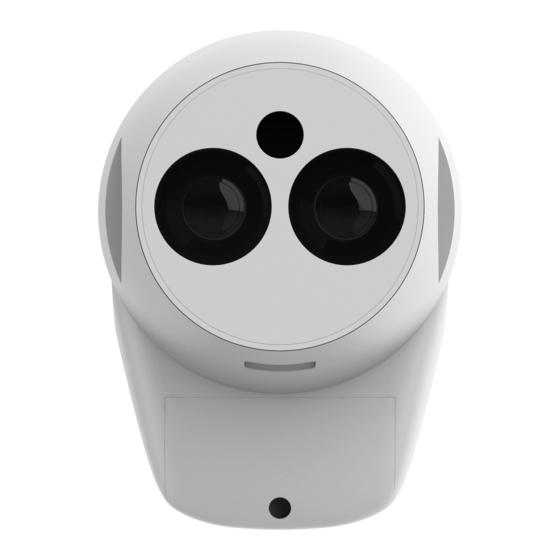
  • Seite 26: Benutzerschnittstelle

    Ausrichtung Benutzerschnittstelle Laserfenster Detektorstatus- Ausrichtung und Einstellungen Anzeige Die Tür sollte am Fireray One angebracht bleiben. Für den Fall, dass sich diese dennoch löst, kann die Befestigung durch Einführen des gezackten Endes wieder angebracht werden. Seite 8...
  • Seite 27 Ausrichtungsstatus-Anzeigen Schiebeschalter Align Operate Alignment-Auto/Manual Targeting-Laser/Prism Fast Alignment-Off/On Latching-Off/On Alarm Threshold Navigationstasten Schalter für Einstellungen Seite 9...
  • Seite 28 Ausrichtung Fireray One kann im schnellen Phase 1 (Zielen) beschreibt den Prozess der Ausrichtungsmodus in weniger als einer Nutzung des Lasers, um den Infrarotstrahl Minute ausgerichtet werden. In diesem Modus nahe genug an den Reflektor zu bringen, damit beträgt der Stromverbrauch während der die Ausrichtung starten kann.
  • Seite 29 In Phase 2 (Ausrichtung) wird der Infrarotstrahl Falls die Ausrichtung fehlschlägt, stellen Sie genau in die Mitte des Reflektors bewegt. sicher, dass die richtige Anzahl an Reflektoren installiert ist, dass der richtige Durchgang Stellen Sie sicher, dass sich der Wahlschalter für angegeben wurde und dass sich keine die Ausrichtung in der linken Position befindet, reflektierenden Flächen im Bereich des...
  • Seite 30 Ausrichtung Prisma-Zielmodus Der Prisma-Zielmodus sollte nur verwendet Die orangefarbene LED blinkt alle zwei Sekunden, werden, wenn der Laser nicht sichtbar ist, z. B. bei wenn der Melder nicht genug Licht vom Reflektor starker Umgebungsbeleuchtung oder über sehr erhält. Die Anzahl der Blinkvorgänge gibt an, große Entfernungen.
  • Seite 31: Manuelle Ausrichtung

    Manuelle Ausrichtung Eine manuelle Ausrichtung sollte nur blinken, hat sich das Signal nicht verändert Verfahren Sie mit den Navigationstasten erfolgen, falls die automatische Ausrichtung und es ist keine weitere Bewegung auf dieser ebenso auf der Links/Rechts-Achse. Beginnen fehlgeschlagen ist, obwohl nachweislich die Achse erforderlich.
  • Seite 32: Selbsthaltender Modus (Latching)

    Einstellungen Alarmschwellwert Empfindlichkeits-Abnahmeprüfung Selbsthaltender Modus (Latching) nach UL Schwellwert Der Alarmzustand wird automatisch Bei erfolgreicher Ausrichtung des Melders zurückgesetzt, wenn die Signalstärke wieder 25 % erfolgt eine Prüfung des ordnungsgemäßen ausreichend ist, sofern nicht der selbsthaltende 35 % Betriebs des Melders sowie dessen Modus (Latching) ausgewählt wurde.
  • Seite 33: Statusanzeigen Und Fehlerbehebung

    Statusanzeigen und Fehlerbehebung Statusanzeigen Reinigung Testen Im Normalbetrieb blinkt die LED zur Anzeige Staubablagerungen werden vom Melder Nach der Installation oder Reinigungen des Melderstatus alle 10 Sekunden, und die automatisch durch Änderung des AGC-Pegels empfiehlt sich die Durchführung eines Alarm- Alarm- und Störungsrelais befinden sich in kompensiert.
  • Seite 34: Technische Daten

    Alarm- und Störungsrelais (VFCO, resistiv) - Kontaktspannung V DC ab. Weitere Informationen unter: Alarm- und Störungsrelais (VFCO, resistiv) - Kontaktstrom www.recyclethis.info. Kabelstärke Gehäuse-Entflammbarkeit UL940 V0 Abmessungen und Gewichte Fireray One Breite (mm) Höhe (mm) Tiefe (mm) Gewicht (kg) Reflektierender Melder einschließlich Sockel Reflektor Seite 16...
  • Seite 35 Manual de usuario Página 1...
  • Seite 36: Contenido De La Caja

    Contenido de la caja Cabeza detectora Fireray One Base Fireray One Reflector Manual de usuario Máscara de rango corto Manual de usuario Página 2...
  • Seite 37: Información General

    Información general Instalación Todas las instalaciones deben cumplir con los reglamentos locales 5 - 20 m = 1 reflector + máscara de rango corto ≥ 0,3 m 20 - 50 m = 1 reflector 0,5 m 5 m - 120 m 50 - 120 m = 4 reflectores NO coloque el detector donde la trayectoria Sitúe el haz lo más alto posible, pero con...
  • Seite 38 Cableado Fireray One contiene software que procesa la salida del detector y genera un estado de fuego y fallo. Este estado Alimentación + se emite utilizando relés sin tensión de modo que se Alimentación - pueda conectar a todos los tipos de panel de control de Rearme externo incendios (FCP , por sus siglas en inglés) estándar.
  • Seite 39 Cuando se utilice más de un detector en una zona única de un panel de control de Alimentación + incendios convencional, es importante Alimentación - elegir el método adecuado de instalación Rearme externo eléctrica. Si la instalación eléctrica no es adecuada, puede que el detector aísle los dispositivos posteriores en la zona en la que haya una condición de fallo.
  • Seite 40: Montaje

    Montaje Base de montaje Marque y perfore orificios para el montaje de Inserte el cable de la cabeza detectora en el Sitúe la cabeza detectora en la base. Fije la base. Empleando el material adecuado (no conector en el PCB en la base. los lados de la cabeza detectora y gire en suministrado) monte la base de forma segura dirección horaria para que encajen.
  • Seite 41 Asegúrese de que las partes saliente y hendidura están alineadas Página 7...
  • Seite 42 Estado del Alineación y ajustes detector indicador La puerta debe permanecer fijada a Fireray One, sin embargo en caso excepcional de que se suelte es posible volver a fijar el anclaje al volver a insertar el extremo punzante. Página 8...
  • Seite 43 Indicadores de estado de Interruptor deslizante alineación Align Operate Alignment-Auto/Manual Targeting-Laser/Prism Fast Alignment-Off/On Latching-Off/On Alarm Threshold Teclas de dirección Interruptor de ajustes Página 9...
  • Seite 44 Alineación Fireray One se alineará en menos de un Etapa 1 (objetivo) es el proceso de uso del minuto si selecciona el modo de alineación láser para acercar el haz de infrarrojos lo rápida. En este modo el consumo de corriente suficiente al reflector de modo que se pueda durante la alineación será...
  • Seite 45 La etapa 2 (alineación) mueve el haz de En caso de que la alineación falle, asegúrese infrarrojos exactamente a la mitad del reflector. de que se ha instalado el número correcto de reflectores, se ha dejado el espacio correcto Asegúrese de que el interruptor de ajuste y de que no hay superficies reflectantes de alineación está...
  • Seite 46 Alineación Objetivo prisma El objetivo prisma solo se debe utilizar cuando La luz LED ámbar parpadeará cada dos segundos si el el láser no se puede ver, por ejemplo en detector no está recibiendo suficiente luz del reflector. condiciones de luz ambiente muy intensa o en El número de parpadeos indica la intensidad de la señal distancias largas.
  • Seite 47 Alineación manual La alineación manual se debe utilizar En caso de que la luz LED ámbar parpadee, Siga este mismo proceso con los botones solamente si falla la alineación automática la señal es más débil y el detector se está de dirección, esta vez en el eje horizontal.
  • Seite 48 Ajustes Umbral de fuego Prueba de aceptación de sensibilidad Modo enclavado Umbral INT5 INT6 El estado de fuego se despejará La alineación correcta del detector automáticamente una vez la intensidad de la 25 % comprobará el funcionamiento correcto del señal se haya recuperado a menos que se 35 % detector y su nivel de sensibilidad.
  • Seite 49 Indicadores de estado y resolución de problemas Indicadores de estado Limpieza Pruebas Durante el funcionamiento normal el indicador El detector compensará de forma automática Después de la instalación o la limpieza, se LED de estado del detector parpadeará en la acumulación polvo al cambiar su nivel de recomienda realizar una prueba de fuego y verde cada 10 segundos y ambos relés de AGC.
  • Seite 50: Información Técnica

    Relés de fuego y fallo (VFCO, resistente): voltaje de contacto V CC Relés de fuego y fallo (VFCO, resistente): corriente de contacto Tamaño del cable Clasificación de inflamabilidad de la carcasa UL940 V0 Dimensiones y peso de Fireray One Anchura Altura (mm) Profundidad Peso (kg) (mm)
  • Seite 51: Guide De L'utilisateur

    Guide de l’utilisateur Page 1...
  • Seite 52: Dans La Boîte

    Dans la boîte Tête de détecteur Fireray One Socle Fireray One Réflecteur Guide de l’utilisateur Masque courte portée Guide de l’utilisateur Page 2...
  • Seite 53: Informations D'ordre Général

    Informations d’ordre général Installation Toutes les installations doivent être conformes à la réglementation locale. 5 - 20 m = 1 réflecteur + masque courte portée ≥ 0,3 m 20 à 50 m = 1 réflecteur 0,5 m 5 m - 120 m 50 à...
  • Seite 54 Câblage Le Fireray One contient un logiciel qui traite les signaux en sortie du détecteur, et déclenche un signal d’incendie Alim + et de panne. Cet signal est transmis à l’aide de relais sans Alim - potentiel, afin de pouvoir être mis en interface avec tous Réarm.
  • Seite 55 Lorsque vous utilisez plus d’un détecteur dans une seule zone d’une FCP conventionnelle, Alim + il est important de choisir la bonne méthode Alim - de câblage. Un mauvais câblage peut amener Réarm. ext. un Détecteur à isoler les appareils ultérieurs dans cette zone, s’il tombe en panne, et peut empêcher ces appareils d’envoyer un signal d’incendie à...
  • Seite 56 Montage Installer le socle Marquer l’emplacement prévu des trous et Branchez le fil de la tête du détecteur dans la Positionner la tête du détecteur sur le socle. percer des trous de montage du socle. fiche de la carte de circuit intégré, se trouvant Saisir les côtés de la tête du détecteur et En utilisant le bon matériel (non fourni), fixer sur le socle.
  • Seite 57 S’assurer que les deux marques s’alignent Page 7...
  • Seite 58 Œil laser Indicateur Alignement et réglages de service du détecteur La plaque doit rester assujettie au Fireray One, cependant dans les rares occasions où elle vienne à se détacher, il est possible de rattacher l’attache en renfonçant l’extrémité pointue. Page 8...
  • Seite 59 Interrupteur Indicateurs d’alignement à glissière Align Operate Alignment-Auto/Manual Targeting-Laser/Prism Fast Alignment-Off/On Latching-Off/On Alarm Threshold Touches de sens Interrupteur de réglage Page 9...
  • Seite 60 Alignement Le Fireray One s’alignera en moins d’une Le niveau 1 (Ciblage) consiste à utiliser le minute si Fast Alignment (alignement laser pour que le faisceau infrarouge soit rapide) est sélectionné. Dans ce mode, suffisamment proche du réflecteur, pour que la consommation de courant pendant l’alignement puisse commencer.
  • Seite 61 L’étape 2 (Alignement) déplace le faisceau Si l’alignement ne se fait pas, assurez-vous infrarouge exactement au milieu du réflecteur. que le nombre correct de réflecteurs soit installé, que le jeu correct ait été laissé, et qu’il Pour choisir l’alignement automatique, s’assurer n’y ait pas de surfaces réfléchissantes autour que l’interrupteur de réglage du ciblage soit à...
  • Seite 62 Alignement Ciblage Prism Le ciblage Prism ne doit être utilisé que lorsque La LED orange clignote toutes les deux secondes le laser ne peut pas être vu, par exemple si le détecteur ne reçoit pas suffisamment de lorsque l’éclairage ambiant est très lumineux, ou lumière en provenance du réflecteur.
  • Seite 63 Alignement manuel Il ne faut aligner manuellement que lorsque Si la LED orange clignote, le signal est moins Une fois l’alignement terminé sur les deux l’alignement automatique ne s’est pas bien intense, et le détecteur est loin du réflecteur. axes, mettre l’interrupteur de réglage 1 sur passé, même après avoir vérifié...
  • Seite 64: Mode De Verrouillage

    Réglages Seuil d’incendie (Fire) Test d’acceptation de la sensibilité Mode de verrouillage conformément à UL Seuil Inter. 5 Inter. 6 Le mode Fire disparaît automatiquement une Un bon alignement du détecteur permettra de fois que l’intensité du signal est retrouvée, sauf 25 % Allumé...
  • Seite 65 Indications de modes de service et Résolution des problèmes Indications de modes de service Nettoyage Essai En fonctionnement normal, la LED de service Le détecteur compense automatiquement Après installation ou nettoyage, il est du détecteur clignote en vert toutes les l’accumulation de poussière en changeant son recommandé...
  • Seite 66: Élimination De L'équipement

    V CC plus amples informations, voir Relais d’incendie et de panne (VFCO, résistif) - Intensité de contact www.recyclethis.info. Section du fil Niveau d’inflammabilité du boîtier UL940 V0 Dimensions et poids du Fireray One Largeur (mm) Hauteur Profondeur Poids (kg) (mm) (mm) Détecteur réfléchissant, notamment le socle «...
  • Seite 67: Guida Per L'utente

    Guida per l’utente Pagina 1...
  • Seite 68 Nel riquadro Testa del rilevatore Fireray One Fireray One Base Riflettore Guida per l’utente Maschera a corto raggio Guida per l’utente Pagina 2...
  • Seite 69: Informazioni Generali

    Informazioni generali Installazione Tutte le installazioni devono essere conformi alle normative locali 5 - 20 m = 1 riflettore + una maschera a corto raggio ≥ 0,3 m 20 - 50 m = 1 riflettore 0,5 m 5 m - 120 m 50 - 120 m = 4 riflettori NON posizionare il rilevatore in posizioni Posizionare il fascio il più...
  • Seite 70 Cablaggio Fireray One contiene il software di elaborazione dell’uscita del rilevatore e genera uno stato incendio Alimentazione + e guasto, emesso utilizzando un relè a zero volt Alimentazione - interfacciabile con qualsiasi tipo di pannello di Ext Reset controllo incendio (FCP , Fire Control Panel). Per collegare un singolo rilevatore a un FCP , utilizzare il seguente diagramma di cablaggio.
  • Seite 71 Quando si usa più di un rilevatore su un’unica zona di un FCP convenzionale, Alimentazione + è importante selezionare il metodo di Alimentazione - cablaggio corretto. A causa del cablaggio Ext Reset un rilevatore può isolare i dispositivi successivi in quella zona in caso di ingresso in condizione di guasto e quindi impedire a tali dispositivi di segnalare una condizione di incendio di ritorno all’FCP .
  • Seite 72: Montaggio Della Base

    Montaggio Montaggio della base Segnare e praticare i fori per montare la Collegare il cavo dalla testa del rilevatore al Posizionare la testa del rilevatore sulla base. base. Utilizzare la ferramenta adatta (non in connettore sul PCB nella Base. Tenere i lati della testa del rilevatore e ruotare dotazione) per montare la base in sicurezza in senso orario per bloccarli insieme.
  • Seite 73 Accertare che la sezione rialzata e quella ribassata siano allineate Pagina 7...
  • Seite 74 Accesso a interfaccia utente Finestra laser Indicatore di Allineamento e stato rilevatore impostazioni La porta dovrà restare attaccata a Fireray One; tuttavia, nei rari casi in cui sarà staccata, sarà possibile fissare nuovamente il collegamento reinserendo l’estremità spinata. Pagina 8...
  • Seite 75 Interruttore a Indicatori di stato allineamento scorrimento Align Operate Alignment-Auto/Manual Targeting-Laser/Prism Fast Alignment-Off/On Latching-Off/On Alarm Threshold Tasti di direzione Interruttore di impostazione Pagina 9...
  • Seite 76 Allineamento Fireray One si allineerà in meno di un minuto Lo stadio 1 (puntamento) è il processo di se si seleziona l’allineamento rapido. In utilizzo del laser in modo che il fascio di questa modalità, il consumo corrente durante infrarossi sia sufficientemente vicino al riflettore l’allineamento sarà...
  • Seite 77 Lo stadio 2 (allineamento) sposta il fascio di In caso di mancato allineamento, accertare infrarossi esattamente al centro del riflettore. che sia installato il numero corretto di riflettori, che il gioco assegnato sia esatto e che non vi Per selezionare l’allineamento automatico, siano superfici riflettenti attorno al riflettore accertare che l’interruttore di impostazione o vicino al percorso del fascio, e riprovare...
  • Seite 78 Allineamento Puntamento a prisma Il puntamento a prisma dovrà essere utilizzato Il LED giallo lampeggerà ogni due secondi soltanto quando il laser non è visibile, per se il rilevatore non riceve luce sufficiente esempio in condizioni di illuminazione forte dal riflettore. Il numero di lampeggi indica la dell’ambiente o a distanze molto lunghe.
  • Seite 79 Allineamento manuale Utilizzare l’allineamento manuale solo quando Se il LED giallo lampeggia, il segnale è minore Completato l’allineamento su ambo gli assi, quello automatico non è riuscito, dopo avere e il rilevatore si allontana dal riflettore. Il spostare quindi l’interruttore di impostazione verificato anche che il numero di riflettori movimento seguente deve essere in direzione 1 a sinistra.
  • Seite 80 Impostazioni Soglia incendio Test di accettazione sensibilità UL Modalità Salvataggio Soglia L’avvenuto allineamento del rilevatore Lo stato incendio sarà annullato quando si controllerà il corretto funzionamento del recupera l’intensità del segnale, tranne qualora rilevatore e il suo livello di sensibilità. sia selezionata la Modalità...
  • Seite 81 Indicazioni di stato e individuazione guasti Indicazioni di stato Pulizia Test Durante il normale funzionamento, il Il rilevatore compenserà automaticamente Dopo l’installazione o dopo un intervento LED dell’indicatore di stato del rilevatore l’accumulo di polvere modificando il livello di pulizia si raccomanda di eseguire il test lampeggerà...
  • Seite 82: Dati Tecnici

    Relè incendio e guasto (VFCO, resistivi) - Tensione contatto V DC Relè incendio e guasto (VFCO, resistivi) - Corrente contatto Diametro del cavo Grado di infiammabilità dell’alloggiamento UL940 V0 Dimensioni e peso di Fireray One Larghezza Altezza (mm) Profondità Peso (kg) (mm)
  • Seite 84 Document Part No. 0044-092-03...

Inhaltsverzeichnis