Herunterladen Inhalt Inhalt Diese Seite drucken
Inhaltsverzeichnis

Werbung

Verfügbare Sprachen
  • DE

Verfügbare Sprachen

  • DEUTSCH, seite 19
Réchauffeur électrique ............................................Notice d'installation et d'utilisation
F
Electric heater........................................................... Instructions for installation and use
GB
Elektroerhitzer..........................................................Montage und Gebrauchsanleitung
D
NL
Verwarmer ................................................................Installatie en gebruikshanleiding
E
Calentador................................................................ Manual de instalación y de uso
P
Aquecedor ................................................................Manual de instalação e utilização
I
Riscaldatore ............................................................. Manuale di installazione e di uso
Ed. 01/2009

Werbung

Inhaltsverzeichnis
loading

Inhaltszusammenfassung für Zodiac Red Line 3

  • Seite 1 Réchauffeur électrique ..........Notice d’installation et d’utilisation Electric heater............Instructions for installation and use Elektroerhitzer............Montage und Gebrauchsanleitung Verwarmer ..............Installatie en gebruikshanleiding Calentador..............Manual de instalación y de uso Aquecedor ..............Manual de instalação e utilização Riscaldatore ............. Manuale di installazione e di uso Ed.
  • Seite 2 Cette notice d’installation fait partie intégrante du produit et doit être impérativement remise à l’utilisateur. Lire attentivement les avertissements contenus dans le présent livret car ils fournissent des indications importantes au niveau de la sécurité d’utilisation et de manutention. Conserver ce livret afin de pouvoir toujours le consulter. L’installation doit être effectuée, conformément aux normes en vigueur et en respectant les instructions du fabricant, par une personne professionnellement qualifiée.
  • Seite 3: Inhaltsverzeichnis

    SOMMAIRE 1 Généralités ..........2 1.1 Conditions générales de livraison ....2 1.2 Tension ............2 1.3 Traitement des eaux ........2 2 Description ..........2 2.1 Présentation ..........2 2.2 Caractéristiques dimensionnelles ....2 3 Mise en place ........3 4 Raccordements ........
  • Seite 4: Généralités

    7- bornier d’alimentation 8- thermoplongeur titane, avec doigts de gant pour sonde de régulation et bulbe de thermostat de sécurité 2.2 Caractéristiques dimensionnelles Modèle A (mm) B (mm) Red Line 3 Red Line 6 Red Line 9 Red Line 12...
  • Seite 5: Mise En Place

    3. MISE EN PLACE Le réchauffeur sera placé dans un local technique (ventilé, sans traces d’humidité, et sans produits d’entretien de piscines stockés), à proximité du filtre de la piscine. De préférence, prévoir un montage en by-pass pour facilité la maintenance sur l’appareil. Il sera fixé au mur horizontalement ou verticalement, à...
  • Seite 6 2 Raccord dement éle ectrique • l'aliment tation élec ctrique du réchauffeu ur doit pr rovenir d'u n dispositi if de prot ection et sectionnem ment (non fo ourni), en c onformité a avec les nor rmes et régl lementation ns en vigueu ur du pays ( France la...
  • Seite 7: Présentation

    Branchement monophase Branchement triphase Bornier Bornier Protection avec disjoncteur Protection avec disjoncteur réchauffeur réchauffeur différentiel 30mA en tête de ligne différentiel 30mA en tête de ligne phases neutre phase neutre Terre Terre shunts Coffret de Coffret de filtration filtration câble d’alimentation câble d’alimentation pour section voir tableau pour section voir tableau...
  • Seite 8: Accès Au Fusible De Protection

    5.3 Accès au fusible de protection 1) ATTENTION ! Mettre l’appareil hors-tension ! 2) démonter le capot du Red Line+, 3) débrancher le régulateur, 4) retirer le capot du régulateur, 5) retirer le fusible de protection (T3,15AH250V). Nota : si hors service => plus d’affichage, ni régulation 6.
  • Seite 9: Défauts

    6.4 Défauts En cas : • d'échauffement anormal, le réchauffeur s'arrête automatiquement grâce au thermostat de sécurité positive de surchauffe (TS) placé sur le coté de l’appareil : 1) retirer le capuchon, 2) réarmer en appuyant sur le bouton central de ce thermostat. •...
  • Seite 10: Schéma Électrique Red Line

    9. SCHEMA ELECTRIQUE RED LINE+ V-j : vert-jaune Bl : bleu M : marron gaine noire B : Blanc ou grise N : noir R : rouge Vi : violet Régulateur à affichage digital Cas : Red Line en coffret 12 Kw 400V/50Hz triphasé...
  • Seite 11 SUMMARY 1. GENERAL ............. 2 1.1 General terms of delivery ........2 1.2 Voltage ..............2 1.3 Water treatment ........... 2 2. DESCRIPTION ..........2 2.1 Presentation ............2 2.2 Dimensions ............2 3. INSTALLATION OF THE UNIT ..... 3 4.
  • Seite 12: General

    5- positive safety (or overheating) thermostat 6- power contactor 7- connection terminal 8- titanium heating element, with pockets for control and high limit sensors 2.2 Dimensions Model A (mm) B (mm) Red Line 3 Red Line 6 Red Line 9 Red Line 12...
  • Seite 13: Installation Of The Unit

    3. INSTALLATION OF THE UNIT The heater shall be be placed in a technical equipment area (ventilated, dry and without stored pool maintenance substances), close to the filter of the pool. It shall be fixed to the wall horizontally or vertically, by rings at the level of the body (not supplied), the apparatus must never be held by the filtering pipes.
  • Seite 14: Electric Connections

    4.2 Electric connections • the electrical supply of the heater must come from a protection and switching device (not supplied) complying with the standards and regulations in force in the country where it is installed (in France, refer to standard NF C 15100). The Red Line from 3 to 9 kW may be supplied by single-phase (230V/1N/50Hz) with a shunt (on terminals R-S-T) and a shunt (on terminals C-N), or in three-phase (400 V / 3 N / 50 Hz), without shunt.
  • Seite 15: Use Of The Control Display

    Three-phase power supply connection Single-phase power supply connection Heater terminal Protection with 30 mA differential Heater terminal Protection with 30 mA differential strip circuit breaker at line head strip circuit breaker at line head Phase Neutral Phases Neutral Earth Earth shunts Filtration Filtration...
  • Seite 16: Access To The Protection Fuse

    5.3 Access to the protection fuse 1) WARNING! Switch off the appliance! 2) remove the cover from the Red Line+, 3) disconnect the regulator, 4) remove the regulator cover, 5) remove the protection fuse(T3,15AH250V). Notice: neither display nor operation if out of order 6.
  • Seite 17: Failure

    6.4 Failure In the event of: • abnormal heating, the heater stops automatically by the positive overheating safety thermostat (TS) placed on the side of the appliance: 1) remove the cap, 2) re-arm by pressing the central button of this thermostat.. •...
  • Seite 18: Electric Diagram Red Line

    9. ELECTRIC DIAGRAM RED LINE+ V-j: green-yellow Bl: blue M: brown black or B: white grey sheath N: black R: red Vi: violet Regulator with digital display Case: Red Line in 12 Kw 400 V / 50 Hz three-phase box CAUTION ! 12 Kw model shall be connected only to...
  • Seite 19 INHALT 1. ALLGEMEINES ......... 2 1.1 Allgemeine Lieferungsbedingungen ....2 1.2 Spannungswerte..........2 1.3 Wasseraufbereitung ........2 2. AUFBAU DES APPARATS ...... 2 2.1 Beschreibung..........2 2.2 Abmessungen..........2 3. INSTALLATION ........3 4. ANSCHLÜSSE .......... 3 4.1 Hydraulische Anschluss ......... 3 4.2 Stromanschluss ..........
  • Seite 20: Allgemeines

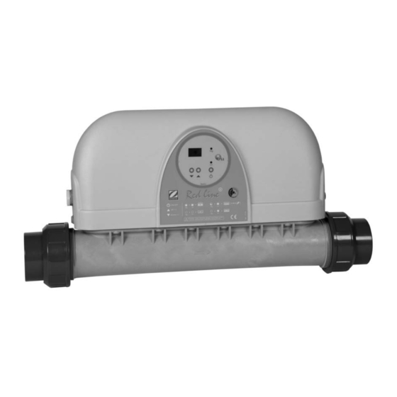
    5- Thermostat positive Sicherheit (oder Überhitzungsthermostat) 6- Leistungsschütz 7- Versorgungsklemmenleiste 8- Titan-Heizstab mit Röhren für die Regelsonde und die Kugel des Sicherheitsthermostats 2.2 Abmessungen Modell A (mm) B (mm) Red Line 3 Red Line 6 Red Line 9 Red Line 12...
  • Seite 21: Anschlüsse

    3. AUFBAU Der Erhitzer wird in einem Betriebsraum (belüftet, ohne Spuren von Feuchtigkeit, ohne gleichzeitige Lagerung von Produkten für Swimmingpools) in der Nähe des Schwimmbeckenfilters installiert. Er wird horizontal oder vertikal mit Ringen (nicht mitgeliefert) auf der Ebene des Körpers befestigt, und das Gerät darf auf keinen Fall von den Rohrleitungen der Filterung gehalten werden.
  • Seite 22: Stromanschluss

    4.2 Stromanschluß • die Stromversorgung des Erhitzers muss von einer Schutz- und Trennvorrichtung (nicht mitgeliefert) gemäß den im Installationsland geltenden Normen und Vorschriften gelieferter werden (in Frankreich die Norm NF C 15100). Die Red Line von 3 bis 9 kW können einphasig (230V/1N/50Hz) mit Nebenwiderstand (auf den Klemmen R-S-T) und Nebenwiderstand (auf den Klemmen C-N) oder mit Drehstrom (400V/3N/50Hz) versorgt werden, ohne Nebenschluss.
  • Seite 23: Drehstrom-Anschluss

    Drehstrom-Anschluss Einphasen-Anschluss Klemmenschiene Klemmenschiene Schutz mit Fehlerstromschutzschalter Schutz mit Fehlerstromschutzschalter Erhitzer Erhitzer 30 mA zu Leitungsbeginn 30 mA zu Leitungsbeginn Phase Neutral Phasen Neutral Erde Erde Nebens chlüsse Filtrationskasten Filtrationskasten Querschnitte des Stromversorgungskabels Querschnitte des Stromversorgungskabels siehe Tabelle siehe Tabelle Stromversorgung 230V Wechselstrom einphasig (Klemme S) + Stromversorgung 400V Wechselstrom Drehstrom (Klemme R-S-T) + Neutralleiter (Klemme C) + Erde...
  • Seite 24: Zugang Zu Den Schutzsicherungen

    5.3 Zugang zu den Schutzsicherungen ACHTUNG! Das Gerät spannungsfrei schalten! 2) die Haube des Red Line+ demontieren, 3) den Regler abstecken, 4) die Reglerhaube entfernen, 5) die Schutzsicherung (T3,15AH250V) entfernen. Hinweis: wenn außer Betrieb => weder Anzeige noch Regelung 6. BAUMERKMALE Ergänzende technische Daten: Modell Leistung des Tauchsieders in L bei Nennspannung *...
  • Seite 25: Überwinterung

    • Wenn die Anzeige auf Display „E0“ (Blinklen) auzeigt: 1) Regelungsprobe außer Betrieb (ausgeschaltet oder kurzgeschlossen), die Probe ersetzen oder sie richtig wieder einschalten, 2) der Fehler wird automatisch verschwinden. • Wenn die Regleranzeige nicht funktioniert, Folgendes kontrollieren: 1) ob Netzstrom anliegt, 2) ob die Schutzsicherung des Wächters nicht außer Betrieb ist (siehe Absatz 5.3).
  • Seite 26: Schaltplan Red Line

    9. SCHALTPLAN RED LINE+ V-j: Grün - Gelb Bl: blau M: braun schwarz oder B: weiss grau Hülle N: schwarz R : rot Vi : violett Steuerung mit digitalanzeige Fall: Red Line in Gehäuse 12 kW 400 V / 50 Hz Drehstrom ACHTUNG! 12 kW modelle sollen nur zu 400V-3N-50 Hz...
  • Seite 27 INHOUD 1 Algemeen ..........2 1.1 Algemene leveringsvoorwaarden ....2 1.2 Spanning ........... 2 1.3 Waterbehandeling ........2 2 Beschrijving ......... 2 2.1 Overzicht ........... 2 2.2 Afmetingen ..........2 3 Installatie ..........3 4 Aansluitingen ........3 4.1 Hydraulische aansluiting ......3 4.2 Elektrische aansluiting .......
  • Seite 28: Algemeen

    5- positieve veiligheidsthermostaat (of tegen oververhitting) 6- vermogenscontactsluiter 7- klemmenbord stroomvoeding 8- weerstand van titanium, met behuizing voor regelingssonde en voeler van de veiligheidsthermostaat 2.2 Afmetingen Model A (mm) B (mm) Red Line 3 Red Line 6 Red Line 9 Red Line 12...
  • Seite 29: Installatie

    3. INSTALLATIE De verwarmer dient in een technische ruimte (geventileerd, zonder vochtigheidssporen en zonder opgeslagen onderhoudsproducten voor zwembaden) geïnstalleerd te worden in de nabijheid van het zwembadfilter. Het dient horizontaal of verticaal aan de muur bevestigd te worden door middel van ringen rond de behuizing (niet meegeleverd), in geen geval mag het ondersteund worden door de leidingen van het filtercircuit.
  • Seite 30: Elektrische Aansluiting

    4.2 Elektrische aansluiting • de elektrische voeding van het verwarmingsapparaat dient afkomstig te zijn van een inrichting met differentieelschakelaar en veiligheidsuitschakelaar (niet meegeleverd), die voldoet aan de van kracht zijnde normen en voorschriften (NF C 15100). De Red Line modellen van 3 tot 9 kW kunnen gevoed worden met eenfase stroom (230V/1N/50Hz) met een shunt (op de R.S.T klemmen) en een shunt (op de C.N klemmen), of met driefasen stroom (400V/3N/50Hz), zonder shunt.
  • Seite 31: Werking Van De Regeling

    Eenfasige aansluiting Driefasige aansluiting Beveiliging met 30 mA Beveiliging met 30 mA Klem voor de Klem voor de differentieelschakelaar, vooraan differentieelschakelaar, vooraan voorverwarmer voorverwarmer Fase Neutraal Fases Neutraal Aarding Aarding shunts Filterkast Filterkast Voor de sectie van de Voor de sectie van de voedingskabel zie tabel voedingskabel zie tabel Voeding 230V alternatief eenfasig (klem S) + Neutraal (klem C)
  • Seite 32: Toegang Tot Veiligheidsstop

    5.3 Toegang tot veiligheidsstop 1) LET OP! Schakel de stroom van het apparaat uit! 2) demonteer de kap van de Red Line+, 3) ontkoppel de regelaar, 4) verwijder de kap van de regelaar, 5) verwijder de veiligheidszekering (T3,15AH250V). Opmerking: indien buiten dienst => geen visuele weergave en geen besturing meer.
  • Seite 33: Het Terug In Werking Stellen

    1) verwijder de dop, 2) voer een reset uit door op de centrale knop van deze thermostaat te drukken. • regelingssonde buiten bedrijf of afgekoppeld, met knipperende weergave “E0”: 1) schakel de stroom van het apparaat uit en vergrendel de toegang tot de stroominschakeling.
  • Seite 34: Elektrisch Schema Red Line

    9. ELEKTRISCH SCHEMA RED LINE+ V-j: groen-geel Bl: blauw M: bruin Zwarte of B: wit grijze huls N: zwart R: rood Vi: violet Regelaar met digitale weergave Situatie : Red Line in driefasige doos 12 Kw 400V/50Hz OPGELET! Voorverwarmer 12 kW een dreifasige 400V/3N/50Hz Zwart met merk van kleur*...
  • Seite 35 ÍNDICE DE MATERIAS 1 Generalidades ..........2 1.1 Condiciones generales de entrega ....2 1.2 Tensión .............. 2 1.3 Tratamiento de las aguas ........2 2 Descripción ..........2 2.1 Presentación ............. 2 2.2 Características dimensionales ......2 3 Instalación ..........3 4 Conexiones ..........
  • Seite 36: Generalidades

    8- calentador de inmersión de titanio con dedos de guante para sonda de regulación y bulbo de termostato de seguridad 2.2 Características dimensionales Modelo A (mm) B (mm) Red Line 3 Red Line 6 Red Line 9 Red Line 12...
  • Seite 37: Instalación

    3. INSTALACIÓN Se instalará el calentador en un local técnico (ventilado, sin trazas de humedad y sin productos almacenados para el mantenimiento de piscinas) junto al filtro de la piscina. Se fijará a la pared horizontal o verticalmente por medio de anillos al nivel del cuerpo (no suministrados), en ningún caso se mantendrá...
  • Seite 38: Conexión Eléctrica

    4.2 Conexión eléctrica • la alimentación eléctrica del calentador debe hacerse a partir de un dispositivo de protección y seccionamiento (no suministrado), en conformidad con las normas y reglamentaciones vigentes del país (en Francia la NF C 15100). Los Red Line de 3 a 9 kW pueden ser alimentados en monofásica (230V/1N/50Hz) con una derivación (en terminales R-S-T) y una derivación (en terminales C-N), o en trifásica (400V/3N/50Hz), sin shunt.
  • Seite 39: Conexión Monofásica

    Conexión monofásica Conexión trifásica Protección diferencial de 30 mA Protección diferencial de 30 mA Regletero Regletero en cabeza de linea en cabeza de linea Calentador Calentador Fase Neutro Fases Neutro Tierra Tierra shunts Caja de Caja de filtración filtración Para seleccionar la secció de cable de Para seleccionar la secció...
  • Seite 40: Acceso Al Fusible De Protección

    5.3 Acceso al fusible de protección 1) ¡ATENCIÓN! Desconectar el aparato de la red eléctrica! 2) desmontar el capó del Red Line+, 3) desconectar el regulador, 4) retirar el capó del regulador, 5) retirar el fusible de protección (T3,15AH250V). Nota: si deteriorado => ninguna visualización, ninguna regulación 6.
  • Seite 41: Interrupción Invernal

    • de sonda de regulación deteriorada o desconectada, con visualización “E0” intermitente: 1) aparato fuera de tensión y consignado volver a conectar o cambiar en pieza estándar la sonda, 2) el defecto “E0” se elimina automáticamente. • Si la pantalla del regulador no funciona, verificar que: 1) la alimentación de la red eléctrica esté...
  • Seite 42: Esquema Eléctrico Red Line

    9. ESQUEMA ELECTRICO RED LINE+ V-j: verde-amarillo Bl: azul M: marrón conducto B: blanco negro o gris N: negro R: rojo Vi: violeta Regulador con visualización digital Caso: Red Line en caja 12 Kw 400V/50Hz trifásico !ATTENCION! El calentador de 12 kW solo disponible en trifásico 400V/3N/50Hz Negro con una etiqueta de color*...
  • Seite 43 ÍNDICE 1. Generalidades ..........2 1.1 Condições gerais da entrega da mercadoria ..2 1.2 Tensão ..............2 1.3 Tratamento de águas ........... 2 2. Descrição ............2 2.1 Apresentação ............2 2.2 Características dimensionais ....... 3 3. Colocação ............. 3 4.
  • Seite 44: Tensão

    4- ½ união Ø63/50 5- termostato de segurança positiva de sobreaquecimento 6- contactor de potência 7- borne eléctrico 8- resistência titânio 2.2 Características dimensionais Modelo A (mm) B (mm) Red Line 3 Red Line 6 Red Line 9 Red Line 12...
  • Seite 45: Colocação

    3. COLOCAÇÃO O aquecimento será colocado num local técnico (ventilado, sem traços de humidade e sem produtos de manutenção de piscinas armazenados) próximo do filtro da piscina. Ele será fixado à parede horizontalmente ou verticalmente ao nível do corpo - em nenhum caso o aparelho deve estar apoiado nas tubagens da filtração.
  • Seite 46: Ligação Eléctrica

    4.2 Ligação eléctrica • a alimentação eléctrica do aquecimento deve proceder de um dispositivo de protecção e de corte (não fornecido), em conformidade com as normas e regulamentação em vigor (a NF C 15100). As Red Line de 3 a 9 kw podem ser alimentadas em monofásico (230V/1N/50Hz) com um shunt (sobre terminais R-S-T) e um shunt (sobre terminais C-N), ou em trifásico (400V/3N/50Hz), sem shunt.
  • Seite 47: Ligação Trifásica

    Ligação monofásica Ligação trifásica Caixa de terminais Caixa de terminais Protecção através de disjuntor Protecção através de disjuntor de aquecimento de aquecimento diferentiel 30mA em cabeça de linha diferentiel 30mA em cabeça de linha Fase Neutro Fases Neutro Terra Terra shunts Quadro Quadro...
  • Seite 48: Acesso Ao Fusível De Protecção

    5.3 Acesso ao fusível de protecção 1) ATENÇÃO! Pôr o aparelho sem tensão! 2) desmontar a tampa do Red Line+, 3) desligar o regulador, 4) retirar a tampa do regulador, 5) retirar o fusível de protecção (T3,15AH250V). Nota: se desactivado => sem visor ou regulação 6.
  • Seite 49: Durante O Inverno

    1) remova a tampa, 2) proceda à reactivação, premindo a tecla central do termostato. • da sonda de regulação desligada, ou com a visualização “E0” a piscar: 1) o aparelho encontra-se desactivado e sem qualquer regulação. Verifique as ligações da sonda ou proceda à...
  • Seite 50: Esquema Eléctrico Red Line

    9. ESQUEMA ELÉCTRICO RED LINE+ V-j: verde-amarelo Bl: azul M: castanho conduta negra B: branco ou cinzenta N: preto R: vermelho Vi: violeta Regulator com visor digital Caso: Red Line em caixa 12 kW 400V/50Hz trifásico Attenção ! A unidade de aquecimento 12kW só...
  • Seite 51 SOMMARIO 1 Generalità ..........2 1.1 Condizioni generali di consegna ....2 1.2 Tensione ............. 2 1.3 Trattamento dell’acqua ....... 2 2 Descrizione ........... 2 2.1 Presentazione..........2 2.2 Caratteristiche dimensionali ....... 2 3 Messa in servizio ........3 4 Collegamenti ......... 3 4.1 Collegamento idraulico .......
  • Seite 52: Generalità

    7- morsettiera di alimentazione 8- termostantuffo in titanio, con pozzetto per sonda di regolazione e bulbo del termostato di sicurezza 2.2 Caratteristiche dimensionali Modello A (mm) B (mm) Red Line 3 Red Line 6 Red Line 9 Red Line 12...
  • Seite 53: Messa In Servizio

    3. MESSA IN SERVIZIO Il riscaldatore sarà posto in un locale tecnico (ventilato, senza tracce d’umidità e senza prodotti di manutenzione delle piscine magazzinate), in prossimità del filtro della piscine. Sarà fissato al muro orizzontalmente o verticalmente, con l’aiuto di anelli a livello del corpo macchina (non forniti), e in nessun caso l’apparecchio deve essere sostenuto dalle tubazioni della filtrazione.
  • Seite 54: Allacciamento Elettrico

    4.2 Allacciamento elettrico • l'alimentazione elettrica del riscaldatore deve essere dotata di un dispositivo di protezione e di sezionamento (non fornito), in conformità alle norme e alle regolamentazioni in vigore nel paese in cui viene installato (in Francia la NF C 15100). I Red Line da 3 a 9 kW possono essere alimentati in monofase (230V/1N/50Hz) con uno shunt (sui morsetti R-S-T) e uno shunt (sui morsetti C-N), o in trifase (400V/3N/50Hz), senza shunt.
  • Seite 55: Collegamento Monofase

    Collegamento monofase Collegamento trifase Morsettiera Morsettiera Protezione con interruttore differenziale da Protezione con interruttore differenziale da 30 mA, riscaldatore 30 mA, nella parte superiore della linea riscaldatore nella parte superiore della linea Fase Neutra Fasi Neutra Terra Terra shunts Quadro Quadro filtrazione filtrazione...
  • Seite 56: Accesso Al Fusibile Di Protezione

    5.3 Accesso al fusibile di protezione 1) ATTENZIONE! Disattivare l’alimentazione dell’apparecchio! 2) smontare la calotta del Red Line+, 3) scollegare il regolatore, 4) rimuovere la calotta del regolatore, 5) rimuovere il fusibile di protezione (T3,15AH250V). Nota : se fuori servizio => nessuna visualizzazione né regolazione 6.
  • Seite 57: Svernamento

    1) togliere il cappuccio, 2) riarmare spingendo il bottone centrale del termostato. • “E0” sonda di regolazione fuori servizio o disconnessa, con segnalazione “E0” lampeggiante : 1) apparecchio fuori tensione procedere alla riconnessione o al cambiamento standard della sonda, 2) l’anomalia “E0” si spegne automaticamente. •...
  • Seite 58: Schema Elettrico Red Line

    9. SCHEMA ELETTRICO RED LINE+ V-j : verde-giallo Bl : blu M : castano Guaina nera B : bianco o grigia N : nero R : rosse Vi : violetta Regulatore con display digitale Caso: Red Line nel quadro 12 kW 400V/50Hz trifase ATTENZIONE ! Riscaldatore 12 kW...
  • Seite 59 DECLARATION DE CONFORMITE déclare que les produits ou gammes ci-dessous : declares that the herewith products or ranges RECHAUFFEURS ELECTRIQUES DE PISCINES ELECTRIC HEATERS FOR POOLS RED LINE sont conformes aux dispositions : are in conformity with the provisions: de la directive COMPATIBILITE ELECTROMAGNETIQUE 89/336/CEE amendée par 93/068/CEE.
  • Seite 60 Chauffage et déshumidification de piscines - Heating and dehumidification of pools Z.P.C.E. - Boulevard de la Romanerie BP 90023 - 49180 Saint Barthélemy d’Anjou Cedex - France Tél. +33 2 41 21 17 30 - Fax +33 2 41 21 12 26 - www.psa-zodiac.com...

Diese Anleitung auch für:

Red line 9Red line 6Red line 12

Inhaltsverzeichnis