Herunterladen Inhalt Inhalt Diese Seite drucken
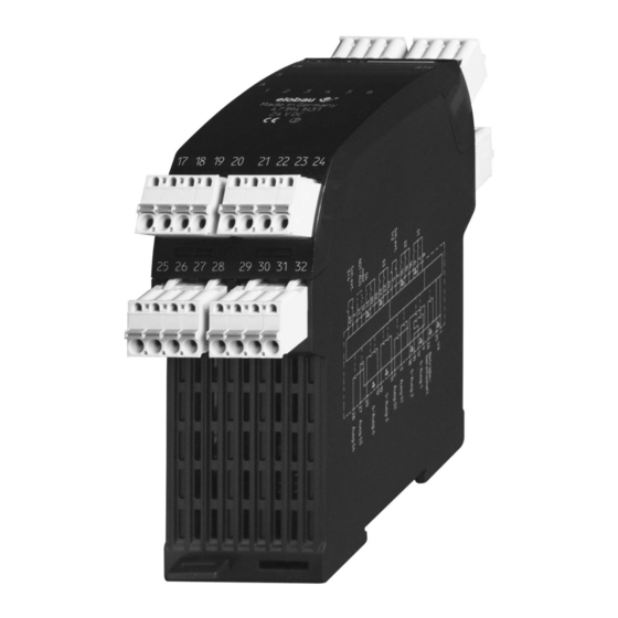
elobau 471 M41 H31 Originalbetriebsanleitung

elobau 471 M41 H31 Originalbetriebsanleitung

Auswerteeinheit
Vorschau ausblenden Andere Handbücher für 471 M41 H31:

Werbung

Verfügbare Sprachen

Verfügbare Sprachen

471 M41 H31
Original-Betriebsanleitung
D
Auswerteeinheit
Translation of the original
GB
Operating instructions Control unit
Traduction de la notice d'utilisation d'origine
F
Unité de contrôle
Traduzione delle istruzioni per l'uso originali
I
Unità di controllo
04.04.2016

Werbung

Inhaltsverzeichnis
loading

Inhaltszusammenfassung für elobau 471 M41 H31

  • Seite 1 471 M41 H31 Original-Betriebsanleitung Auswerteeinheit Translation of the original Operating instructions Control unit Traduction de la notice d'utilisation d'origine Unité de contrôle Traduzione delle istruzioni per l’uso originali Unità di controllo 04.04.2016...
  • Seite 2 900565 / 04.04.2016...
  • Seite 3 900565 / 04.04.2016...
  • Seite 4: Technische Daten

    Technische Daten 1.1 Anschlussbelegung An die Auswerteeinheit können maximal vier Sensoren angeschlossen werden. Klemme Belegung 1, 25 24 V DC Betriebsspannung 6, 7, 8 Sensoreingang 1 (S1), zwei Schließer (wenn nicht nötig: überbrücken) 14, 15, 16 Sensoreingang 2 (S2), zwei Schließer (wenn nicht nötig: überbrücken) 2, 5 externer Schütz 1 und 2...
  • Seite 5: Elektrische Und Mechanische Daten

    1.2 Typen-Benennung/Varianten Zur Erklärung der Typen-Benennung der Auswerteeinheiten dienen folgendes Beispiel und die Tabelle. Beispiel: 471 M41 H31 4ab cde fgh Platzhalter Merkmal Bedeutung Gehäusetyp und Gehäusebreite 45 mm Gehäusebreite Ausführung Microcontroller-Ausführung Eingänge 4 Eingänge Betriebsspannung 24 V Sonstiges Kat. 4 laut DIN EN ISO 13849-1...
  • Seite 6 Schaltleistung 2,4 W Kontrollausgänge max. Anzahl der **Schaltspiele bei 3 x 10 0,5 A Schaltstrom (ohmsche Last, 250 V AC) max. Anzahl der **Schaltspiele bei 2,5 x 10 3 A DC Schaltstrom (ohmsche Last, 250 V AC) Gebrauchsdauer in Jahren Sicherung 1 A, flink Betriebsspannung...
  • Seite 7: Led-Anzeigen

    LED-Anzeigen Bedeutung bei leuchtender LED Betriebsspannung liegt an Betriebsbereitschaft besteht Sensor 1, beide Kontakte betätigt Sensor 2, beide Kontakte betätigt Sensor 3, beide Kontakte betätigt Sensor 4, beide Kontakte betätigt / NOT-HALT nicht betätigt Sicherheitsausgang 1 durchgeschaltet Sicherheitsausgang 2 durchgeschaltet Sicherheitsausgang 3 durchgeschaltet Sicherheitsausgang 4 durchgeschaltet Schalter...
  • Seite 8: Bestimmungsgemäßer Einsatz

    Bestimmungsgemäßer Einsatz Die Auswerteeinheit ausschließlich zum Schutz vor Gefährdungen einsetzen. 2.1 Sicherheit/Gefahren Generell Sicherstellen, dass die Auswerteeinheit nur von speziell ausgebildetem, au- torisiertem Personal montiert und in Betrieb genommen wird. Sicherstellen, dass die entsprechenden Sicherungen (siehe Technische Da- ten) verwendet werden. Sicherungen niemals überbrücken oder reparieren. Auswerteeinheit nur in unversehrtem Zustand betreiben.
  • Seite 9 Funktion Die Auswerteeinheit besteht aus zwei unabhängigen Einheiten. Einheit Bestandteile Sensoreingänge S1 und S2 Eingang Schütz extern 1 und 2 Sicherheitsausgänge SA1 und SA2 Kontrollausgänge A1 und A2 Sensoreingänge S3 und S4 Eingang Schütz extern 3 und 4 Sicherheitsausgänge SA3 und SA4 Kontrollausgänge A3 und A4 Einheit einsetzbar als...
  • Seite 10: Montage

    Wenn der Sensoreingang 4 auf 4-Draht-Anschluss umgestellt ist: Die Schalter 5 schalten den Sensoreingang 4 von Schließer/Schließer auf Schließer/Öffner um. Die Einheit überwacht den Sensoreingang 4 auf Querschluss. Zur Erweiterung der 4 Sensoreingänge folgende Schnittstellen verwenden: Typ 363 V98 für 8 Sensoren ohne Sensorkontrolle Typ 364 097 für 4 Sensoren mit Sensorkontrolle Die Schalter 1 bis 4 verzögern das Abschalten des Sicherheitsausgangs 4.
  • Seite 11 Inbetriebnahme Lebensgefahr durch Stromschlag!  Sicherstellen, dass die Auswerteeinheit nur von speziell ausge- bildetem, autorisiertem Personal montiert und in Betrieb ge- nommen wird. Gefahr Obere Abdeckung der Auswerteeinheit entfernen. Schalter einstellen. Sicherstellen, dass beide Schalterreihen die gleiche Einstellung haben. Obere Abdeckung der Auswerteeinheit schließen. Sicherstellen, dass alle Sensoren betätigt sind.
  • Seite 12: Störungsbeseitigung

    Störungsbeseitigung Wenn während des Betriebs Fehler auftreten: Die LED Betriebsbereitschaft erlischt. Der entsprechende Ausgang schaltet ab. 6.1 Betriebsbereitschaft wiederherstellen Wenn an einem Sensor länger als drei Sekunden ein unterschiedlicher Schaltzu- stand der beiden Kontakte anlag: Beide Schließer dieses Sensors öffnen. Die Betriebsbereitschaft schaltet wieder ein.
  • Seite 13: Wartung

    Wartung 7.1 Betrieb mit Schnittstelle Ein oder mehrere Schließer der angeschlossenen Sensoren sind geöffnet. Kontakte an den Sensoreingängen schließen. Die LED Betriebsspannung leuchtet. Die Auswerteeinheit schaltet den Ausgang durch. Die Auswerteeinheit ist betriebsbereit. 7.2 Entsorgung Verpackung und verbrauchte Teile gemäß den Bestimmungen des Landes, in dem das Gerät installiert wird, entsorgen.
  • Seite 14 Schaltbeispiele 8.1 Anschluss einer Schnittstelle 363 V98 900565 / 04.04.2016...
  • Seite 15: Erweiterung Der Sicherheitsausgänge

    8.2 Erweiterung der Sicherheitsausgänge 900565 / 04.04.2016...
  • Seite 16 8.3 2-Hand-Steuerung 900565 / 04.04.2016...
  • Seite 17 8.4 Anschluss einer Schnittstelle 364097 900565 / 04.04.2016...
  • Seite 18: Not-Aus Mit Querschlusserkennung

    8.5 NOT-AUS mit Querschlusserkennung 900565 / 04.04.2016...
  • Seite 19: Anschluss Sensor 4/Schließer-Öffner

    8.6 Anschluss Sensor 4/Schließer-Öffner 900565 / 04.04.2016...
  • Seite 20: Technical Data

    Technical data 1.1 Terminal assignment Up to 4 sensors can be connected to the control unit. Terminal Assignment 1, 25 24 V DC operating voltage 6, 7, 8 Sensor input 1 (S1), contact maker (to be bridged, if not needed) 14, 15, 16 Sensor input 2 (S2), contact maker (to be bridged, if not needed) 2, 5...
  • Seite 21: Electrical And Mechanical Data

    1.2 Type denomination/Variants The following example and table are given to explain the type denomination of the control units. Example: 471 M41 H31 4ab cde fgh Placeholder Characteristic Meaning Housing type and Housing width 45 mm housing width Version Microcontroller version...
  • Seite 22: Led Displays

    Max. number of **switching operations 2,5 x 10 for 3 A switching current (ohmic load, 250 V AC) Service in Years Operating voltage fuse 1 A, fast-action Fuse safety outputs 3 A each Operating temperature 0 °C ... +55 °C Storage and transportation temperature -25 °C ...
  • Seite 23: Appropriate Use

    Meaning when LED is lit Sensor 2, both contacts actuated Sensor 3, both contacts actuated Sensor 4, both contacts actuated / EMERGENCY STOP not actuated Safety output 1 is switched through Safety output 2 is switched through Safety output 3 is switched through Safety output 4 is switched through Switches Switch...
  • Seite 24 Ensure that the control unit is only used for protection against dangers. Ensure that all safety requirements applying for the machine in question are observed. Ensure that all European guidelines and national laws/guidelines applying are observed. Ensure that the switches are always switched over in a deenergized state. Function The control unit consists of two independent units.
  • Seite 25: Installation

    The unit checks the external-contactor loop before switching on the safety out- puts. Switches 7 switch a sensor input 4 to 4-wire connection. When sensor input 4 has been switched to 4-wire connection: Switches 5 switch the sensor input 4 from contact maker/contact maker to contact maker/contact breaker.
  • Seite 26: Putting Into Operation

    Putting into operation Danger of electrocution!  Ensure that the control unit is only installed and put into opera- tion by specially-trained authorised personnel. Danger Remove the top cover of the control unit. Set the switches. Ensure that both rows of switches are set identically. Close the top cover of the control unit.
  • Seite 27: Troubleshooting

    Troubleshooting As soon as there occurs an error during operation: The operational standby LED goes off. The respective output switches off. 6.1 Restoring device to a state of readiness for operation If a different switched state of both contacts was present for more than 3 seconds on a sensor: Open both contact makers of the sensor.
  • Seite 28: Maintenance

    Maintenance 7.1 Using with interface One or more contact makers of the connected sensors are open. Close the contacts at the sensor inputs. The operating voltage LED is on. The control unit switches through the output. The control unit is ready for operation. 7.2 Disposal Dispose of used parts and unwanted packaging in accordance with the regula- tions of the country in which the device is installed.
  • Seite 29 Example circuits 8.1 Connection of a 363 V98 interface 900565 / 04.04.2016...
  • Seite 30 8.2 Extension of the safety outputs 900565 / 04.04.2016...
  • Seite 31 8.3 2-hand-control 900565 / 04.04.2016...
  • Seite 32 8.4 Connection of a 364097 interface 900565 / 04.04.2016...
  • Seite 33 8.5 EMERGENCY OFF with cross short detection 900565 / 04.04.2016...
  • Seite 34 8.6 Connection sensor 4/contact maker/breaker 900565 / 04.04.2016...
  • Seite 35 Notizen / Notes / Notes / Appunt 900565 / 04.04.2016...
  • Seite 36: Caractéristiques Techniques

    Caractéristiques techniques 1.1 Affectation des bornes Un maximum de quatre capteurs peuvent être raccordés à l'unité de contrôle. Borne Affectation 1, 25 24 V CC tension de service 6, 7, 8 Entrée capteur 1 (S1), deux contacts de travail (si inutile : ponter) 14, 15, 16 Entrée capteur 2 (S2), deux contacts de travail (si inutile : ponter) 2, 5...
  • Seite 37: Caractéristiques Électriques Et Mécaniques

    1.2 Désignation du type/variantes Se reporter à l'exemple suivant et au tableau pour expliquer la désignation du type des unités de contrôle. Exemple : 471 M41 H31 4ab cde fgh Caractères Caractéristique Signification variables Type de boîtier et lar- Largeur de boîtier 45 mm geur de boîtier...
  • Seite 38 Nombre max. de **cycles à un courant de commutation 3 x 10 de 0,5 A (charge ohmique, 250 V AC) Nombre max. de **cycles à un courant de commutation 2,5 x 10 de 3 A (charge ohmique, 250 V AC) Durée d'utilisation en années Fusible tension de service 1 A, rapide...
  • Seite 39 Affichages DEL Signification de la DEL allumée Tension de service appliquée L'état de fonctionnement est donné Capteur 1, les deux contacts actionnés Capteur 2, les deux contacts actionnés Capteur 3, les deux contacts actionnés Capteur 4, les deux contacts actionnés/ARRÊT D'URGENCE non actionné...
  • Seite 40: Utilisation Conforme

    Utilisation conforme Utiliser l'unité de contrôle uniquement pour assurer une protection contre des dangers. 2.1 Sécurité / dangers Généralités S'assurer que l'unité de contrôle est uniquement montée et mise en service par du personnel spécialement formé et autorisé. S'assurer que les fusibles adéquats (voir Caractéristiques techniques) sont utilisés.
  • Seite 41 Fonction L'unité de contrôle est composée de deux unités indépendantes. Unité Composants Entrées de capteur S1 et S2 Entrée contacteur externe 1 et 2 Sorties de sécurité SA1 et SA2 Sorties de contrôle A1 et A2 Entrées de capteur S3 et S4 Entrée contacteur externe 3 et 4 Sorties de sécurité...
  • Seite 42 Lorsque l'entrée de capteur 4 est commutée sur la connexion à 4 fils : Les commutateurs 5 commutent l'entrée de capteur 4 de contact de travail/ contact de travail à contact de travail/contact de repos. L'unité surveille d'éventuels courts-circuits transversaux sur l'entrée de cap- teur 4.
  • Seite 43: Mise En Service

    Mise en service Danger de mort par électrocution !  S'assurer que l'unité de contrôle est uniquement montée et mise en service par du personnel spécialement formé et autori- sé. Danger Retirer le capot supérieur de l'unité de contrôle. Régler les commutateurs. S'assurer que les deux rangées de commutateurs ont le même réglage.
  • Seite 44: Suppression Des Pannes

    Suppression des pannes Si des erreurs se produisent pendant le fonctionnement : La DEL état de fonctionnement s’éteint. La sortie correspondante est désactivée. 6.1 Remettre en état de fonctionnement Si les deux contacts d'un capteur ont eu un état de commutation différent pen- dant plus de trois secondes : Ouvrir les deux contacts de travail de ce capteur.
  • Seite 45: Entretien

    Entretien 7.1 Fonctionnement avec interface Un ou plusieurs contacts de travail des capteurs raccordés sont ouverts. Fermer les contacts sur les entrées pour capteur. La DEL tension de service est allumée. L’unité de contrôle active la sortie. L'unité de contrôle est prête à fonctionner. 7.2 Élimination Éliminer les emballages et les pièces usagées conformément aux dispositions nationales du pays dans lequel l’appareil est installé.
  • Seite 46: Exemples De Connexions

    Exemples de connexions 8.1 Connexion d’une interface 363 V98 900565 / 04.04.2016...
  • Seite 47 8.2 Extension des sorties de sécurité 900565 / 04.04.2016...
  • Seite 48 8.3 Commande à deux mains 900565 / 04.04.2016...
  • Seite 49 8.4 Connexion d’une interface 364097 900565 / 04.04.2016...
  • Seite 50 8.5 ARRÊT D'URGENCE avec détection de court-circuit transversal 900565 / 04.04.2016...
  • Seite 51 8.6 Connexion du capteur 4/travail-repos 900565 / 04.04.2016...
  • Seite 52: Specifiche Tecniche

    Specifiche tecniche 1.1 Assegnazione dei collegamenti All'unità di controllo possono venir collegati fino a 4 sensori. Morsetto Assegnazione 1, 25 24 V CC tensione di esercizio 6, 7, 8 Ingresso sensore 1 (S1), due contatti NO (se non necessario: cavallottare) 14, 15, 16 Ingresso sensore 2 (S2), due contatti NO (se non necessario: cavallottare)
  • Seite 53: Dati Elettrici E Meccanici

    1.2 Denominazione dei tipi/varianti I seguenti esempi e tabelle spiegano le denominazione dei tipi delle unità di con- trollo. Esempio: 471 M41 H31 4ab cde fgh Carattere/ Caratteristica Significato Stringa Tipo e larghezza Larghezza dell'alloggiamento dell'alloggiamento 45 mm Esecuzione Esecuzione microcontroller...
  • Seite 54 Corrente di commutazione uscite di 100 mA controllo Potenza di interruzione uscite di con- 2,4 W trollo Numero massimo di **cicli di commuta- 3 x 10 zione con corrente di commutazione pari a 0,5 A (carico ohmico, 250 V AC) Numero massimo di **cicli di commuta- 2,5 x 10 zione con corrente di commutazione...
  • Seite 55 Indicazione LED Significato a LED acceso Tensione di esercizio presente Idoneità operativa attiva Sensore 1, entrami i contatti inseriti Sensore 2, entrami i contatti inseriti Sensore 3, entrami i contatti inseriti Sensore 4, entrami i contatti inseriti/ARRESTO DI EMER- GENZA non attivato Uscita di sicurezza 1 collegata direttamente Uscita di sicurezza 2 collegata direttamente Uscita di sicurezza 3 collegata direttamente...
  • Seite 56: Uso Conforme Alla Destinazione

    Uso conforme alla destinazione Utilizzare l'unità di controllo solo quale protezione dai pericoli. 2.1 Sicurezza/pericoli In generale Assicurarsi che l'unità di controllo venga montata e messa in servizio esclu- sivamente da personale specializzato, adeguatamente istruito ed autorizza- Assicurarsi che vengano utilizzati fusibili conformi all'impiego (vedi Specifiche tecniche).
  • Seite 57 Funzione L'unità di controllo è composta da due unità indipendenti. Unià Componenti Ingressi sensore S1 e S2 Ingresso relè esterno 1 e 2 Uscite di sicurezza SA1 e SA2 Uscite di controllo A1 e A2 Ingressi sensore S3 e S4 Ingresso relè...
  • Seite 58 Quando l'ingresso sensore 4 è commutato sul collegamento a 4 conduttori: Gli interruttori 5 commutano l'ingresso sensore 4 da contatto NO/NO a con- tatto NO/NC. L'unità verifica l'ingresso sensore 4 in relazione ad eventuali chiusure trasver- sali. Per ampliare i 4 ingressi sensore usare le seguenti interfacce: Modello 363 V98 per 8 sensori senza controllo sensore Modello 364 097 per 4 sensori con controllo sensore Gli interruttori 1 - 4 ritardano la disattivazione dell’uscita di sicurezza 4.
  • Seite 59: Messa In Funzione

    Messa in funzione Pericolo di morte dovuto a scosse elettriche!  Assicurarsi che l'unità di controllo venga montata e messa in servizio esclusivamente da personale specializzato, adeguata- mente istruito ed autorizzato. Pericolo Togliere la copertura superiore dell’unità di controllo. Regolare l’interruttore. Assicurarsi che i due banchi di interruttori abbiano la stessa impostazione.
  • Seite 60: Eliminazione Dei Disturbi

    Eliminazione dei disturbi Se durante l’esercizio si verificano degli errori: Il LED dell’idoneità operativa si spegne. La corrispondente uscita si disattiva. 6.1 Operazione per ripristinare la funzionalità Se su un sensore era presente per più di tre secondi una condizione di commu- tazione diversa dei due contatti: Aprire entrambi i contatti NO di questo sensore.
  • Seite 61: Manutenzione

    Manutenzione 7.1 Funzionamento con interfaccia Uno o più contatti NO dei sensori collegati sono aperti. Chiudere i contatti degli ingressi sensore. Il LED della tensione di esercizio si accende. L’unità di controllo collega direttamente l’uscita. L'unità di controllo è pronta all'uso. 7.2 Smaltimento Smaltire l’imballo ed i componenti usati in conformità...
  • Seite 62 Esempi di commutazione 8.1 Collegamento di un’interfaccia 363 V98 900565 / 04.04.2016...
  • Seite 63 8.2 Ampliamento delle uscite di sicurezza 900565 / 04.04.2016...
  • Seite 64 8.3 Comando a 2 mani 900565 / 04.04.2016...
  • Seite 65 8.4 Collegamento di un’interfaccia 364097 900565 / 04.04.2016...
  • Seite 66 8.5 ARRESTO DI EMERGENZA con riconoscimento chiu- sure trasversali 900565 / 04.04.2016...
  • Seite 67 8.6 Collegamento sensore 4/contatti NO-NC 900565 / 04.04.2016...
  • Seite 68 GmbH & Co. KG Zeppelinstraße 44 D-88299 Leutkirch +49-7561-970-0 / www.elobau.de EU-Konformitätserklärung EU- Declaration of Conformity Hiermit erklären wir, dass das nachfolgend aufgeführte Produkt aufgrund der Konzipierung und Bauart den Sicherheits- und Gesundheitsanforderungen der unten genannten EU-Richtlinien entspricht. Hereby we officially validate that the below listed component comply with the health and safety requirements of the following European Directive...
  • Seite 69 Artikelnummer / Article Number / Référence / Codice articolo: 900565 Version / Version / Version / Versione: 2.0 Datum / Date / Date / Data: 04.04.2016 Seiten / Pages / Pages / Pagine: 69 elobau GmbH & Co. KG Zeppelinstr. 44 88299 Leutkirch Germany Tel.:...

Inhaltsverzeichnis