
Verwandte Anleitungen für Feig Electronic OBID i-scan ID ISC.ANT800/600-DA


Inhaltszusammenfassung für Feig Electronic OBID i-scan ID ISC.ANT800/600-DA
- Seite 1 MONTAGE ® OBID i-scan INSTALLATION ID ISC.ANT800/600-DA Antenna with dynamic Tuner (deutsch / english) draft public (B) 2005-07-07 M50101-0de-ID-B.doc...
- Seite 2 ® OBID i-scan Montage ID ISC.ANT800/600-DA deutsche Version ab Seite 3 english version from page 22 FEIG ELECTRONIC GmbH Seite 2 von 38 M50101-0de-ID-B.doc...
- Seite 3 Hinweise jederzeit dankbar. Die in diesem Dokument gemachten Installationsempfehlungen gehen von günstigsten Rahmenbedingun- gen aus. FEIG ELECTRONIC GmbH übernimmt keine Gewähr für die einwandfreie Funktion in systemfrem- den Umgebungen. FEIG ELECTRONIC GmbH übernimmt keine Gewährleistung dafür, dass die in diesem Dokument enthal- tenden Informationen frei von fremden Schutzrechten sind.
-
Seite 4: Inhaltsverzeichnis
Geräteanordnungen mit der Antenne ID ISC.ANT800/600-DA Standard-Applikationen ....................14 Funk-Regularien im EU-Raum und den USA ............15 5.2.1 Zugelassenen Readereinstellung ..................15 5.2.2 Spezieller Antennenaufbau ...................16 Technische Daten Zulassung ........................20 5.3.1 Europa (CE) ........................20 5.3.2 USA (FCC) ........................20 Lieferumfang: FEIG ELECTRONIC GmbH Seite 4 von 38 M50101-0de-ID-B.doc... - Seite 5 Obwohl dieses Gerät die zulässigen Grenzwerte für elektromagnetische Felder nicht überschreitet, sollten Sie einen Mindestabstand von 25 cm zwischen dem Gerät und Ihrem Herzschrittmacher einhalten und sich nicht für längere Zeit in unmittelbarer Nähe des Geräts bzw. der Antenne auf- halten. FEIG ELECTRONIC GmbH Seite 5 von 38 M50101-0de-ID-B.doc...
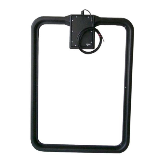
- Seite 6 Die Antenne kann sowohl für die Güter- als auch in der Personenerkennung verwendet werden. Sie ist für die Montage im Innen- wie auch den Außenbereich geeignet Die Vorzugsrichtung eines Smart Label ist parallel zur Antennenfläche. Die maximale Reichweite wird über der Mitte der Antennenfläche erreicht. FEIG ELECTRONIC GmbH Seite 6 von 38 M50101-0de-ID-B.doc...
-
Seite 7: Montage Und Anschluss
Bild 1: Montagezeichnung ID ISC.ANT800/600-DA (alle Maße in mm) Hinweis: Die Antenne muss einen Mindestabstand von 10 cm von Metallteilen haben! Schon ab 50 cm Abstand zu Metallteilen muss mit Einbußen in der Lesereichweite ge- rechnet werden. FEIG ELECTRONIC GmbH Seite 7 von 38 M50101-0de-ID-B.doc... -
Seite 8: Hinweise Zur Kabelführung Der Antennenzuleitung
Power Splitters je ein EMV-Ringkern da=28 mm eingebaut werden. Dafür ist das Koaxialkabel mindestens vier mal, eng anliegend durch den EMV-Ringkern zu schleifen. Der Abstand zwischen Readeranschluss und Ringkern sollte dabei maximal 10 cm betragen. Bild 2: Montage EMV-Ringkern auf Anschlusskabel FEIG ELECTRONIC GmbH Seite 8 von 38 M50101-0de-ID-B.doc... -
Seite 9: Inbetriebnahme
Zur Inbetriebnahme wird die Servicesoftware ISOStart ab Version 6.06 und ® ® auf einem Personal Computer mit Microsoft Windows Betriebssystem benötigt. Die ® Servicesoftware finden Sie auf der OBID i-scan CD der Firma FEIG ELECTRONIC GmbH. FEIG ELECTRONIC GmbH Seite 9 von 38 M50101-0de-ID-B.doc... -
Seite 10: Aufbau Der Antenne
LR200 3,6m (+7,2m) 3,5m (+7,2m) 12-24VDC 4.3 Einstellung des Power Splitters Der Power Splitter dient nur zur Spannungsversorgung des Antennentuners. Er ist gemäß Tabelle 1 einzustellen. Tabelle 1: Jumperstellung am Power-Splitter used FEIG ELECTRONIC GmbH Seite 10 von 38 M50101-0de-ID-B.doc... -
Seite 11: Einstellung Des Antennentuners
4.5 Abgleich der Antenne Zum Abgleichen der Antenne ist die Software ISOStart zu öffnen und zunächst die aktuelle Konfi- guration des Reader auszulesen: Step Procedure Note ISOStart Software starten „Detect“ ausführen..dem „New-File Assistant“ folgen... FEIG ELECTRONIC GmbH Seite 11 von 38 M50101-0de-ID-B.doc... - Seite 12 Zum Abgleich ist der „ISO- Host Mode“ zu aktivieren durch „Write“ setzen Menü „Commands“ auswählen „Start Tuning“ auf Tuner- Address 1 durchführen. Die Abgleichprozedur kann bis zu 30s andauern. Abgleichergebnis mit „Get Antenna Values“ kontrollie- ren. FEIG ELECTRONIC GmbH Seite 12 von 38 M50101-0de-ID-B.doc...
- Seite 13 ® OBID i-scan Montage ID ISC.ANT800/600-DA Step Vorgang Hinweis Wenn Tuning Status nicht „OK“ Schritt 7 wiederholen. FEIG ELECTRONIC GmbH Seite 13 von 38 M50101-0de-ID-B.doc...
-
Seite 14: Geräteanordnungen Mit Der Antenne Id Isc.ant800/600-Da
Antennenaufbauten abgeleitet werden können. Folgende Application-Notes erhältlich: Application-Note: Configuring and Tuning an Antenna Gate from four or six ID ISC.ANT800/600-DA Antennas (N50101-xe-ID-B) Application-Note: Configuring and Tuning an Antenna Gate from from ID ISC.ANT800/600-DA Antennas (N50101-xe-ID-B) FEIG ELECTRONIC GmbH Seite 14 von 38 M50101-0de-ID-B.doc... -
Seite 15: Funk-Regularien Im Eu-Raum Und Den Usa
Timeslots - CFG 8 / ISO-MODE 16 Timeslots 16 Timeslots / NO-TS Complete Timeslot length at Complete Timeslot length at Inverntory Comand Option – „NO TAG“ „NO TAG“ CFG 8 / ISO-CMD-OPTION / BREAK FEIG ELECTRONIC GmbH Seite 15 von 38 M50101-0de-ID-B.doc... -
Seite 16: Spezieller Antennenaufbau
Neben der Möglichkeit des Abschirmens von Antennen zum Einhalten der Regularien kann durch spezielle Antennenaufbauten eine Kompensation des magnetischen Feldes durch entgegenge- setzte Feldrichtungen erreicht werden. Dies wurde von FEIG ELECTRONIC GmbH für verschiede- ne Antennenaufbauten getestet und in einem Messlabor überprüft. - Seite 17 Der EMV-Ringkern ∅ 41 mm x 15 mm ist genau in der Mitte des Antennenkabels zu montieren. Dafür ist das Koaxialkabel mindestens zehn mal, eng anliegend durch den Ringkern zu schleifen. Dieser Ringkerne sind dem Reader beigelegt. Bild 4: Montage zweier Ringkerne auf Koaxialkabel FEIG ELECTRONIC GmbH Seite 17 von 38 M50101-0de-ID-B.doc...
-
Seite 18: Technische Daten
Temperaturbereich – Betrieb –25°C bis +55°C – Lagerung –25°C bis +60°C • Vibration EN60068-2-6 10 Hz bis 150 Hz : 0,075 mm / 1 g • Schock EN60068-2-27 Beschleunigung : 30 g FEIG ELECTRONIC GmbH Seite 18 von 38 M50101-0de-ID-B.doc... - Seite 19 UL 1950 (Auf Anfrage) – USA *Label 46 x 75 mm , über der Antennen Mitte, Empfindlichkeit / Minimale Feldstärke H =85mA/m rms, parallele Ausrichtung des Labels zur Antenne. Sendeleistung 4 W. FEIG ELECTRONIC GmbH Seite 19 von 38 M50101-0de-ID-B.doc...
-
Seite 20: Zulassung
Unauthorized modifications may void the authority granted under Federal communica- tions Commission Rules permitting the operation of this device. Lieferumfang: Folgende Komponenten sind im Lieferumfang enthalten: Antenne ID ISC.ANT800/600-DA FEIG ELECTRONIC GmbH Seite 20 von 38 M50101-0de-ID-B.doc... - Seite 22 ELECTRONIC GmbH does not give any guarantee promise for perfect function in cross environments. FEIG ELECTRONIC GmbH assumes no responsibility for the use of any information contained in this manual and makes no representation that they free of patent infringement. FEIG ELECTRONIC GmbH does not convey any license under its patent rights nor the rights of others.
- Seite 23 11.2 RF regulations in EU countries and the USA............33 11.2.1 Permissible Reader settings ..................33 11.2.2 Special antenna construction..................34 Technical Data 11.3 Approval ........................38 11.3.1 Europe (CE)......................38 11.3.2 USA (FCC)........................38 Scope of delivery: FEIG ELECTRONIC GmbH Page 23 of 38 M50101-0de-ID-B.doc...
- Seite 24 Although this device does not exceed the permissible limits for electromagnetic fields, you should keep a minimum distance of 25 cm between the device and your pacemaker, and not remain in the direct vicinity of the device or antenna for longer periods of time. FEIG ELECTRONIC GmbH Page 24 of 38 M50101-0de-ID-B.doc...
- Seite 25 The antenna can be used for detecting either goods or persons. It is suitable for indoor or outdoor installation. The preferred orientation of a Smart Label is parallel to the antenna area. The maximum range is achieved over the center of the antenna area. FEIG ELECTRONIC GmbH Page 25 of 38 M50101-0de-ID-B.doc...
-
Seite 26: Installation And Wiring
Fig. 5: Installation drawing for ID ISC.ANT800/600-DA (all dimensions in mm) Note: The antenna must be kept a minimum of 10 cm away from metal parts! Even at distances of 50 cm or closer a sacrifice in reading range must be anticipated. FEIG ELECTRONIC GmbH Page 26 of 38 M50101-0de-ID-B.doc... -
Seite 27: Notes On Routing The Antenna Cable
EMC ring core as shown in the illustration. The distance between the Reader connection and the ring core should be a maximum of 10 cm. Fig. 6: EMC ring core installed on an antenna cable FEIG ELECTRONIC GmbH Page 27 of 38 M50101-0de-ID-B.doc... -
Seite 28: Startup
ISOStart Version 6.06 or higher ® ® on a personal computer running under Microsoft Windows is required. The service software can ® be found on the OBID i-scan CD available from FEIG ELECTRONIC GmbH. FEIG ELECTRONIC GmbH Page 28 of 38 M50101-0de-ID-B.doc... -
Seite 29: Constructing The Antenna
10.3 Setting the Power Splitter The Power Splitter is used to supply the antenna tuner with power. It is set as shown in Tabelle 1. Table 4: Jumper settings on the Power Splitter used FEIG ELECTRONIC GmbH Page 29 of 38 M50101-0de-ID-B.doc... -
Seite 30: Setting The Antenna Tuner
To tune the antenna, open the ISOStart software and first read out the current Reader configuration: Step Procedure Note Start ISOStart Software Run „Detect“ ..Follow the „New-File Assistant“ ..and read out the current Reader configuration FEIG ELECTRONIC GmbH Page 30 of 38 M50101-0de-ID-B.doc... - Seite 31 Select „Start Tuning“ for Tuner Address 1. The tuning procedure may take up to 30s. Check tuning results by using „Get Antenna Values“. If Tuning Status is not „OK“ repeat Step 7. FEIG ELECTRONIC GmbH Page 31 of 38 M50101-0de-ID-B.doc...
-
Seite 32: Device Arrangements With The Id Isc.ant800/600-Da Antenna
The following Application Notes are available: Application-Note: Configuring and Tuning an Antenna Gate from four or six ID ISC.ANT800/600-DA Antennas (N50101-xe-ID-B) Application-Note: Configuring and Tuning an Antenna Gate from from ID ISC.ANT800/600-DA Antennas (N50101-xe-ID-B) FEIG ELECTRONIC GmbH Page 32 of 38 M50101-0de-ID-B.doc... -
Seite 33: Rf Regulations In Eu Countries And The Usa
Timeslots - CFG 8 / ISO-MODE 16 Timeslots 16 Timeslots / NO-TS Complete Timeslot length at Complete Timeslot length at Inverntory Comand Option – „NO TAG“ „NO TAG“ CFG 8 / ISO-CMD-OPTION / BREAK FEIG ELECTRONIC GmbH Page 33 of 38 M50101-0de-ID-B.doc... -
Seite 34: Special Antenna Construction
In addition to shielding the antennas to conform with national regulations, special antenna constructions can be used to achieve compensation of the magnetic field by means of opposing field directions. This has been tested by FEIG ELECTRONIC GmbH for various antenna constructions and verified in a testing laboratory. - Seite 35 The ∅ 41 mm x 15 mm EMC ring core is installed exactly in the middle of the antenna cable. Wind the coax cable at least 10 times tightly around the ring core. These ring cores are included with the Reader. Fig. 8: Installing two ring cores on coaxial cable FEIG ELECTRONIC GmbH Page 35 of 38 M50101-0de-ID-B.doc...
-
Seite 36: Technical Data
Temperature range – Operating –25°C to +55°C – Storage –25°C to +60°C • Vibration EN60068-2-6 10 Hz to 150 Hz : 0.075 mm / 1 g • Shock EN60068-2-27 Acceleration : 30 g FEIG ELECTRONIC GmbH Page 36 of 38 M50101-0de-ID-B.doc... - Seite 37 EN 60950 (on request) UL 1950 (on request) – USA *Label 46 x 75 mm , centered of the antenna, sensitivity H =85mA/m rms, label aligned parallel to antenna. RF power 4 W. FEIG ELECTRONIC GmbH Page 37 of 38 M50101-0de-ID-B.doc...
-
Seite 38: Approval
Equipment Classification according to ETSI EN 300 330 and ETSI EN 301 489: Class 2 11.3.2 USA (FCC) 12 Scope of delivery: The following components are included in the scope of delivery: Antenne ID ISC.ANT800/600-DA FEIG ELECTRONIC GmbH Page 38 of 38 M50101-0de-ID-B.doc...