
Verwandte Anleitungen für Feig Electronic OBID i-scan ID ISC.ANTS370


Inhaltszusammenfassung für Feig Electronic OBID i-scan ID ISC.ANTS370
- Seite 2 ® OBID i-scan Montage ID ISC.ANTS370/270 deutsche Version ab Seite 3 english version from page 14 FEIG ELECTRONIC GmbH Seite 2 von 23 M10413-1de-ID-B.doc...
- Seite 3 Hinweise jederzeit dankbar. Die in diesem Dokument gemachten Installationsempfehlungen gehen von günstigsten Rahmenbedingun- gen aus. FEIG ELECTRONIC GmbH übernimmt keine Gewähr für die einwandfreie Funktion in systemfrem- den Umgebungen. FEIG ELECTRONIC GmbH übernimmt keine Gewährleistung dafür, dass die in diesem Dokument enthal- tenden Informationen frei von fremden Schutzrechten sind.
-
Seite 4: Inhaltsverzeichnis
Bestellbezeichnung ....................6 Lieferumfang ....................... 6 Reinigung ........................6 Abmessungen und Montage Abmessungen ......................7 Montage unter dem Tisch................... 8 Anschluss an RFID-Reader Technische Daten Zulassung ........................12 5.1.1 Europa (CE) ......................12 FEIG ELECTRONIC GmbH Seite 4 von 23 M10413-1de-ID-B.doc... -
Seite 5: Sicherheits- Und Warnhinweise - Vor Inbetriebnahme Unbedingt Lesen
Obwohl dieses Gerät die zulässigen Grenzwerte für elektromagnetische Felder nicht überschreitet, sollten Sie einen Mindestabstand von 25 cm zwischen dem Gerät und Ihrem Herzschrittmacher einhalten und sich nicht für längere Zeit in unmittelbarer Nähe des Geräts bzw. der Antenne aufhalten. FEIG ELECTRONIC GmbH Seite 5 von 23 M10413-1de-ID-B.doc... -
Seite 6: Leistungsmerkmale
Mikrofasertuch. Die Oberflächen dürfen nur mit Lösung aus Wasser mit wenig Spülmittel gereinigt werden. Die Verwendung von Spiritus, Alkohol, Verdünnung, Glasreiniger oder anderen scharfen Reinigungsmitteln ist verboten und führt zur Beschädigung der Acrylglasplatte. FEIG ELECTRONIC GmbH Seite 6 von 23 M10413-1de-ID-B.doc... -
Seite 7: Abmessungen Und Montage
Die Außenmaße und die Position der Befestigungsdurchbrüche der Shielded Pad Antenne sind in folgender Abbildung dargestellt: Alle Maße in mm (inch): 275,7 (10,85) 240 (9,44) Abbildung 1: Außenmaße und Position der Befestigungsdurchbrüche (Unterseite) FEIG ELECTRONIC GmbH Seite 7 von 23 M10413-1de-ID-B.doc... -
Seite 8: Montage Unter Dem Tisch
Die Tischplatte selbst darf nicht aus Metall oder sonstigem elektrisch Leitfähigen Material bestehen. Mit Hilfe eines Akkuschraubers sollte die Antenne mit 4 Schrauben an die Tischplatte ge- schraubt werden. FEIG ELECTRONIC GmbH Seite 8 von 23 M10413-1de-ID-B.doc... -
Seite 9: Anschluss An Rfid-Reader
Der Anschluss der Antenne ID ISC.ANTS370/270 erfolgt über das 2,3 m lange Koaxialkabel mit SMA-Stecker. Es wird empfohlen, für die optimale Performance des Systems das Antennenkabel nicht zu kürzen oder zu verlängern. FEIG ELECTRONIC GmbH Seite 9 von 23 M10413-1de-ID-B.doc... -
Seite 10: Technische Daten
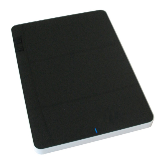
Koaxialkabel RG58; 50 ; 2,3 m Antennenanschluss SMA Stecker 50 Signalgeber optisch LED blau (DC-Offset 5..7 V) Umgebungsbedingungen Temperaturbereich - Betrieb -25...+55°C - Lagerung -25...+70°C 5 bis 95% nicht betauend Relative Luftfeuchte FEIG ELECTRONIC GmbH Seite 10 von 23 M10413-1de-ID-B.doc... - Seite 11 ® OBID i-scan Montage ID ISC.ANTS370/270 Angewendete Normen EN 301 489 Sicherheit - Niederspannung EN 60950 - Human Exposure EN 50364 FEIG ELECTRONIC GmbH Seite 11 von 23 M10413-1de-ID-B.doc...
-
Seite 12: Zulassung
Die Funkanlage entspricht, bei bestimmungsgemäßer Verwendung den grundlegenden Anforde- rungen des Artikels 3 und den übrigen einschlägigen Bestimmungen der R&TTE Richtlinie 1999/5/EG vom März 1999. Equipment Classification gemäß ETSI EN 301 489: Class 2 FEIG ELECTRONIC GmbH Seite 12 von 23 M10413-1de-ID-B.doc...