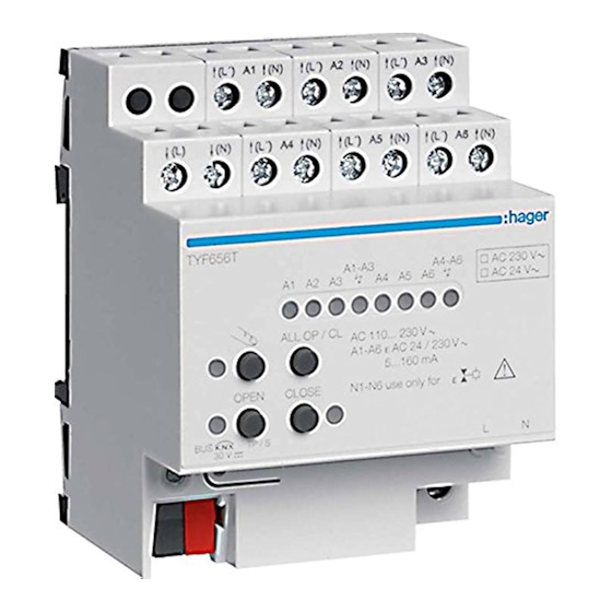
hager TYF656T Anleitung
Heizungsaktor 6f reg
Verfügbare Sprachen
Verfügbare Sprachen
Quicklinks
TYF 656 T
A4 A5 A6
A1 A2 A3
AC 230 /24 0
ALL OFF
A1- A4 µ 16 AX
A5- A6 max
N5- N6 use only
OFF /
ON /
TP / S
30 V
s
TYF656T
Safety instructions
• Electrical equipment may only be installed and
fitted by electrically skilled persons.
• Serious injuries, fire or property damage
possible. Please read and follow manual fully.
• Danger of electric shock. Always disconnect
before carrying out work on the devise or load.
At the same time, take into account all circuit
breakers that supply dangerous voltage to the
device or load.
• Danger of electric shock. Device is not suitable
for disconnection from supply voltage.
The load is not electrically isolated from the
mains even when the device is switched off.
• These instructions are an integral part of
the product, and must remain with the end
customer.
Device components
Figure 1: Front view
(1) Supply of electrothermal valve drives
(2) Button field for manual operation
(3) Programming button and LEDs
(4) KNX connection
(5) Connection for mains supply
(6) Status LEDs for outputs
(7) Connection of electrothermal actuators
Function
System informatione
This device is a product of the KNX system and
complies with the KNX directives. Detailed technical
knowledge obtained in KNX training courses is a
prerequisite to proper understanding.
The function of this device depends upon the
software. Detailed information on loadable software
and attainable functionality as well as the software
itself can be obtained from the manufacturer´s
product database. Planning, installation and
commissioning of the device are carried out
with the aid of KNX-certified software. The latest
versions of product database and the technical
descriptions are available on our website.
1
Heating actuator
z
6-gang RMD
Heizungsaktor 6f REG
e
A7 A8
V
AC 250 V
V
. 50 mA AC 250
for
N
L
Intended use
- Switching of electrothermal actuators for heaters
or cooling ceilings
- Installation in distribution boxes on DIN rail
according to EN 60715
Product characteristics
- Switching operation or PWM operation
- Actuators with characteristics opened or closed
without power
- Valve drives 230 V or 24 V controllable
- Outputs can be operated manually, construction
site mode
- Feedback in manual mode and in bus mode
- Disabling of individual outputs manually or via bus
- Overload-protected, short circuit-protected, error
message with LED
- Protection against jamming valves
- Forced position
- Various setpoints for forced position or emergency
operation in case of bus failure for summer or
winter
- Cyclical monitoring of the input signals can be
parameterized
- Feedback via bus, e.g. in case of mains failure,
overload or sensor failure
- Bus connection with standard bus connecting
terminal
PWM operation: electrothermal actuators only
have the positions "open" and "closed". In PWM
operation, switch-on and switch-off during the drive's
cycle time achieves an almost constant behaviour.
Overload protection
In order to protect the device and connected
actuators, in case of overload the device determines
which output is involved and switches it off.
Nonoverloaded outputs continue to work, which
means that the rooms in question are still heated.
- In case of major overloads the actuator initially
switches all off the outputs A1...A6 off.
- In the case of more minor overloads the actuators
switches output groups A1...A3 and/or A4...A6 off.
- The actuator determines the overloaded output in
up to 4 test cycles.
- If in the event of only a minor overload it is not
possible to unambiguously identify any output as
overloaded, then the actuator switches individual
outputs off one after the other.
- The overload can be reported to the bus for each
output.
LED display:
- Overload LED flashes slowly: Test cycle active.
- Overload
completed.
Operation
Figure 2: Operating elements – Overview
Bn?.:
V2.7.0
LED
flashes
quickly:
Test
(6) A1...A6: Status LEDs for outputs
]1-3, ]4-6: Display "Overload/short-circuit" for
output group
(8) Button � – Manual operation
(9) LED � – On: Continuous manual mode active
(10) OPEN button – Open valve
(11) LED OPEN – On: Valve opened, manual
operation
(12) CLOSE button – Close valve
(13) LED CLOSE – On: Valve closed, manual
operation
(14) ALL OP / CL button – Central operating
function for all outputs: Open and close all
valve alternatively
Status display and output behaviour
The Status LEDs A1...A6 (6) show whether the
current flow is switch on or switched off at the
appropriate output. The connected heating or
cooling valves open and close according to their
characteristics.
Valve drive
LED on
Deenergised
Heating/
closed
cooling
Valve opened
Deenergised
Off
opened
Valve closed
- LED flashes slowly: Output in manual mode
- LED
flashes
quickly:
continuous manual mode
Operating modes
- Bus operation: Operation via push-button sensors
or other bus devices
- Short-term manual operation: Manual operation
locally with button field, automatic return to bus
operation.
- Continuous manual mode: Exclusively manual
operation on the device
No bus operation is possible in manual mode.
No manual mode is possible in case of bus
failure.
The behaviour after bus failure and return can
be set.
The manual mode can be disabled in ongoing
operation via a bus telegram.
Switching on the temporary manual control
Operation using the button field is programmed
and not disabled.
• Press the � button briefly.
Status-LET A1 flashes, LED � remains off.
After 5 seconds without a button-press, the
actuator returns automatically to bus operation.
Switching off temporary manual operation
The device is in short-term manual mode.
• No button-press for 5 seconds.
- or -
cycle
• Press � button briefly as many time as necessary
until the actuator leaves the shorttime manual
mode.
LEDs A1... no longer flash, but rather indicate the
output status.
Switching on permanent manual control
Operation using the button field is programmed
and not disabled.
• Press the � button for at least 5 seconds.
LED � is illuminated, status LED A1 flashes,
continuous manual mode is switched on.
LED off
Off
Valve closed
Heating/
cooling
Valve opened
Output
disabled
via
6LE000480A

Verwandte Anleitungen für hager TYF656T


Inhaltszusammenfassung für hager TYF656T
- Seite 3 (14) Taste ALL OP / CL – Zentrale Bedienfunktion für alle Ausgänge: Alle Ventile abwechselnd Bestimmungsgemäßer Gebrauch öffnen und schließen - Schalten elektrothermischer Stellantriebe für TYF656T Statusanzeige und Ausgangsverhalten Heizungen oder Kühldecken - Einbau in Unterverteiler auf Hutschiene nach DIN Die Status-LED A1...A6 (6) zeigen, ob am...
- Seite 4 Gerät anschließen Inbetriebnahme LED � ist aus, Busbetrieb ist eingeschaltet. Adresse und Anwendungssoftware laden Ausgänge bedienen • Busspannung einschalten. Im Handbetrieb können die Ausgänge unmittelbar bedient werden. • Programmier-Taste drücken. Das Gerät befindet sich im permanenten oder • Physikalische Adresse in das Gerät laden. kurzzeitigen Handbetrieb.