Inhaltszusammenfassung für Morningstar EcoBoost MPPT
Seite 1
EcoBoost MPPT Solar Charging System Controller Installation, Operation and Maintenance Manual For the most recent manual revisions, see the version at: www.morningstarcorp.com www.morningstarcorp.com MODELS EB-MPPT-20 EB-MPPT-20M EB-MPPT-30 EB-MPPT-30M EB-MPPT-40 EB-MPPT-40M MAXIMUM POWER POINT TRACKING...
Rated Load Current Auxilliary USB Charging..........33 *Array voltage should never exceed this limit Inspection and Maintenance........33 **These power levels refer to the maximum wattage the EcoBoost MPPT can process. Higher power arrays can be used without damaging the controller. Continued...
• Read all of the instructions and cautions in the manual before beginning installation. • There are no user serviceable parts inside the EcoBoost MPPT. Do not disassemble or attempt to repair the controller. WARNING: Risk Of Electrical Shock. NO POWER OR ACCESSORY TERMINALS ARE ELECTRICALLY ISOLATED FROM DC INPUT, AND MAY BE ENERGIZED WITH HAZARDOUS SOLAR VOLTAGE.
Seite 4
The grounding conductor must be secured against any to the elements and do not allow water to enter the accidental detachment. controller. • Install the EcoBoost MPPT in a location that prevents Battery Safety casual contact. The EcoBoost MPPT heatsink can become very hot during operation.
• Disconnect charging source prior to connecting or 2.1 Overview disconnecting battery terminals. Thank you for choosing the EcoBoost MPPT charge control- • Determine if battery is inadvertently grounded. If so, remove the source of contact with ground. Contact with ler with TrakStar MPPT Technology.
1 - Charging Status / Error LED Indicates charging and error condition statuses. The features of the EcoBoost MPPT are shown in Figure 2-1 2 - Heatsink / Grounding Screw (M4 screw for grounding heatsink) below. An explanation of each feature is provided below.
N OTE: The use of a Remote Temperature Sensor is Explosion strongly recommended. Controller location, air flow, and Never install the EcoBoost MPPT in an enclosure system power can drastically affect the local temperature sensor with vented/flooded batteries. Battery fumes reading.
These protection devices are external to the EcoBoost MPPT controller, and must be a • Loose power connections and /or corroded wires maximum of 25 amps for the EB-20/M, 35 amps for the EB- may result in resistive connections that melt wire 30/M, and 50 amps for the EB-40/M.
Seite 9
Multiply the voltage settings by two (2) for 24 volt systems. NOTE: These settings are general guidelines for use at the operator’s discretion. The EcoBoost MPPT can be programmed to satisfy a wide range of charging parameters. Consult the battery manufacturer for optimal battery charge settings.
To load (+) and To battery (+) 15 cm (-) terminals and (-) terminals Figure 3-3. Wiring the EcoBoost MPPT 5 cm REFER TO FIGURE 3.3 WHEN USING THE WIRING INSTRUCTIONS 15 cm BELOW. Figure 3-2. Proper Clearances for Passive Cooling Installation EcoBoost MPPT Operator’s Manual...
Seite 11
If no Remote Temperature Sensor (RTS) is connected, This unit is not provided with a GFDI device. This use the EcoBoost MPPT within 3m (10 ft) of the batteries. Internal charge controller must be used with an external GFDI Temperature Compensation will be used if the RTS is not device as required by local regulations.
Seite 12
(disconnected) before installing the system wires. With the solar disconnect open, connect the solar (PV) array wires to the EcoBoost MPPT solar terminals. Use caution, since the solar array will produce current whenever in sunlight. A solar disconnnect is a convenient way to break the PV connection when necessary.
Seite 13
Do not wire any AC inverter to the load terminals of the the the charging status, and then the three battery state- EcoBoost MPPT. Damage to the load control circuit may result. of-charge (SOC) LEDs blink in sequence (G-Y-R), confirm- An inverter should be wired to the battery.
• the EcoBoost MPPT is in LVD (red LED on) OPERATION • there is a short circuit in the load (LEDs blinking R/G – Y) • there is an overload condition (LEDs blinking R/Y - G) 4.1 TrakStar MPPT Technology •...
Seite 15
NOTE: These settings are general guidelines for use at the operator’s discretion. The EcoBoost MPPT can be programmed to satisfy a wide range of charging parameters. Consult the battery manufacturer for optimal battery charge settings. Absorp. Float Equalize Absorp. Equalize...
DC loads with a current draw greater Under load, the battery voltage will sag in proportion to the than 20 or 30A, depending on the EcoBoost MPPT model in current draw of the load. Without the current compensation use.
20, 30 or 40 amp maximum rating. An over- Flashing Error sized solar array will not operate at peak power. The solar On Solid array should be less than the EcoBoost MPPT nominal max. ( with heart- Critical Error input power rating for optimal performance. See Section beat 7.0 - Technical Specifications for more information.
4.6 Custom Settings High Temperature Current Limit The EcoBoost MPPT will limit the solar input current if the 4.6.1 Adjusting Set-points with the Meter Display heatsink temperature exceeds safe limits. Solar charge current will be tapered back (to 0 amps if needed) to reduce The EcoBoost MPPT is available in metered and the heatsink temperature.
For metered models, see the included complete meter map insert, also available in the EcoBoost MPPT support documents at: 1) The EcoBoost MPPT has two USB-A ports for use as www.morningstarcorp.com charging sources for small electronics. Energy is taken from the system battery, so any auxilliary charging must be bal- 4.6.2 Meter Display Operation...
G sequencing. If the load current exceeds the maximum Clean the heatsink fins with a clean, dry rag. load current rating, the EcoBoost MPPT will disconnect the load. The greater the overload the faster the load will be Inspect all wiring for disconnected.
Seite 21
To resume operation without an RTS, Error status LED: Flashing red. Battery status LEDs: disconnect all power to the EcoBoost MPPT and then R-Y-G sequencing. If a settings switch is changed while reconnect. If the controller is re-started with the failure...
With a multi-meter, check the voltage at the battery complete start up or begin charging. terminals on the EcoBoost MPPT. Battery voltage must be Re-try the firmware update. The firmware must be 10 vdc or greater. If the voltage on the battery terminals of successfully loaded before the controller will start up.
LIMITED WARRANTY Morningstar Solar Controllers and Inverters Electrical: Nominal Battery Voltage 12 volts or 24 volts (all) The EcoBoost MPPT is warrantied to be free from defects in Battery Voltage Range 10-35 volts (all) material and workmanship for a period of TWO (2) years from the Voltage Accuracy 0.1% +/- 50mV (all)
Seite 24
10 minutes High Heatsink Temperature - Load Disconnect LVD Override 10 minutes Load Short-Circuit Maximum # LVD overrides No limit unless Load Over-Current (not customizable) V_batt < Instant LVD Heatsink Temperature Limit RTS Terminals Technical Specifications EcoBoost MPPT Operator’s Manual...
à l’installation. Tension nominale 12 / 24 V 12 / 24 V 12 / 24 V • Le EcoBoost MPPT ne contient aucune pièce susceptible de la batterie d'être réparée par l'utilisateur. Ne démontez pas le Tension maximale en régulateur et n'essayez pas de le réparer. circuit ouvert du 120 V...
MPPT. Les bornes d’alimentation négatives de l’EcoBoost MPPT • L’EcoBoost MPPT ne contient pas de fusibles ni de sont ordinaires et doivent être mises à la terre conformément sectionneurs. N’essayez pas de le réparer.
• Portez des gants et des bottes de caoutchouc. • Utilisez des outils dotés de poignées isolées et éviter Les caractéristiques du EcoBoost MPPT sont illustrées dans la de placer des outils ou des objets métalliques figure 2-1 ci-dessous. Chaque caractéristique est expliquée.
Le dissipateur thermique en aluminium (situé sur la face postérieure) Capteur de température distant (modèle : RTS) dissipe la chaleur du régulateur (pour plus de fiabilité, le EcoBoost MPPT Le RTS mesure la température de la batterie pour une est refroidi de manière entièrement passive) compensation précise de la température.
Seite 30
• Les bornes de la batterie de l’EcoBoost MPPT peuvent INSTALLATION être raccordées à une batterie ou à un banc de batteries. Les instructions suivantes mentionnent une batterie 3.1 Remarques générales relatives à l’installation unique, il est toutefois entendu que les bornes de la batterie peuvent être raccordées à...
Seite 31
Le boîtier DIP illustré sur la figure 3.1 ci-dessous est utilisé pour En règle générale, la tension système spécifique est connue, définir les paramètres de fonctionnement de l’EcoBoost MPPT. il est donc préférable de régler les interrupteurs DIP 2 et 3 en conséquence. Le paramètre d’auto-détection ne doit être utilisé...
Seite 32
Interrupteur 7 : Égalisation de la batterie Vérifiez que le régulateur n’a subi aucun dommage pendant Mode Interrupteur 7 le transport. Montez l’EcoBoost MPPT sur une surface Égalisation manuelle verticale (4 vis autotaraudeuses n° 8 incluses). Serrez les vis Égalisation automatique de fixation en faisant attention à ne pas fissurer le boîtier en plastique.
Seite 33
PV (Voc) compensée en température et le courant de charge n'excèdent pas les caractéristiques nominales du modèle EcoBoost MPPT en cours d’installation. Plusieurs régulateurs peuvent être installés en parallèle sur un même banc de batterie afin d’accroître le courant de charge total.
Seite 34
• EcoBoost MPPT-20 10 mm MISE EN GARDE : en cas de non-utilisation du RTS, • EcoBoost MPPT-30 10 mm l’EcoBoost MPPT utilisera le capteur de température • EcoBoost MPPT-40 10 mm local pour la compensation. REMARQUE : le câble du RTS peut être raccourci si OU, une zone de coupe équivalente ou supérieure aux...
Seite 35
PAS les deux) Ne reliez pas de d’onduleur AC sur les bornes de charge de l’EcoBoost MPPT. Le circuit de contrôle de charge peut ÉTAPE 5 : Connexions solaires - voir le schéma ci-dessous être endommagé. Un onduleur doit être relié à la batterie.
Seite 36
Plusieurs raisons peuvent expliquer un défaut d'allumage de la charge : • l’EcoBoost MPPT est en sectionnement à basse tension (DEL rouge allumée) • la charge présente un court-circuit (les DEL rouge et verte clignotent en alternance avec la DEL jaune) Le calibre des fusibles ou du •...
Charge en 4 étapes 4.1 Technologie TrakStar MPPT L’EcoBoost MPPT est doté d’un algorithme de charge de la batterie en 4 étapes permettant une charge rapide, efficace L’EcoBoost MPPT utilise la technologie de suivi du point et sûre de la batterie. La figure 4-1 illustre le déroulement de puissance maximale (MPPT) TrakStar de Morningstar afin...
Seite 38
Les options de charge préréglées de la batterie du Le principal objectif de la fonction de contrôle de la charge EcoBoost MPPT figurent dans les tableaux 4-1 et 4-2 ci-dessous. consiste à déconnecter les charges du système lorsque Tous les paramètres de tension indiqués correspondent à des la batterie se décharge jusqu’à...
Rouge Erreur critique (avec pulsations²) Pas de voyant DEL. L’EcoBoost MPPT limite le courant de la batterie à la tension nominale maximale de 20, 30 ou 40 A. ¹ les pulsations consistent à allumer brièvement la DEL d’état toutes Les générateurs PV trop puissants ne fonctionneront pas les 5 secondes à la puissance de crête.
Seite 40
Démarrer le Cf. liste complète des Tension cible test d’éclairage écrans d’historique en Température de EcoBoost MPPT limite le courant de la batterie à la valeur Rétablir les ligne ou sur la notice la batterie réglages d’usine Détection de Graphiques du courant nominal maximal.
LVD, HVD, ou en cas de déconnexion de charge demandée par l’utilisateur (d’une commande La structure des menus du compteur du EcoBoost MPPT de compteur, par exemple). En cas de LVD, HVD et comporte deux axes principaux : les principaux écrans déconnexion de charge, la charge principale et les...
Seite 42
Vérifiez que tous les Court-circuit de la charge conducteurs de terre sont DEL d’état d'erreur : rouge clignotant. DEL d’état de la correctement mis à la terre. batterie : clignotements R / V – J. Tableau 4-5. Calendrier d’entretien Utilisation Manuel de l’utilisateur EcoBoost MPPT...
Seite 43
120 V, le générateur le cas, cette erreur est probablement critique. Contactez un sera déconnecté jusqu'à ce que la Voc retombe en dessous distributeur Morningstar agréé pour obtenir une assistance. de la tension nominale maximale en toute sécurité. DEL d'état DEL SOC de Capteur de température distant (RTS)
12 V ou 24 V (tous) Plage de tension de la batterie 10-35 V (tous) L’EcoBoost MPPT est garanti contre tout défaut de matériaux et Précision de la tension 0,1 % +/- 50 mV (tous) de main d’œuvre pour une période de DEUX (2) ans à compter Courant maximal de la batterie 20 A...
Surcharge de la charge Contrôle de l’éclairage (DIP 1 réglé sur ON) : Limitation de température du dissipateur thermique Paramètre de la Bornes du RTS minuterie d’éclairage Crépuscule-aurore (par défaut) Minuterie du test d’éclairage 5 minutes Spécifications techniques Manuel de l’utilisateur EcoBoost MPPT...
WARNUNG: Kennzeichnet eine potenziell gefährliche verhindern Sie das Eindringen von Wasser in den Regler. Situation. Seien Sie extrem vorsichtig beim Ausführen • Installieren Sie den EcoBoost MPPT an einem Ort, an dem dieser Tätigkeit. zufälliger Kontakt vermieden wird. Der Kühlkörper des ACHTUNG: Kennzeichnet einen für Sicherheit und...
Stromkreis haben). hoher Kurzschlussströme oder ein Feuer- oder • Lesen Sie sorgfältig die Anleitung des Akkuherstellers, Explosionsrisiko aufgrund austretender Gase darstellen. bevor Sie Akkus für den EcoBoost MPPT installieren, Beachten Sie die entsprechenden Vorsichtsmaßnahmen. anschließen oder entfernen. WARNUNG: Explosionsgefahr.
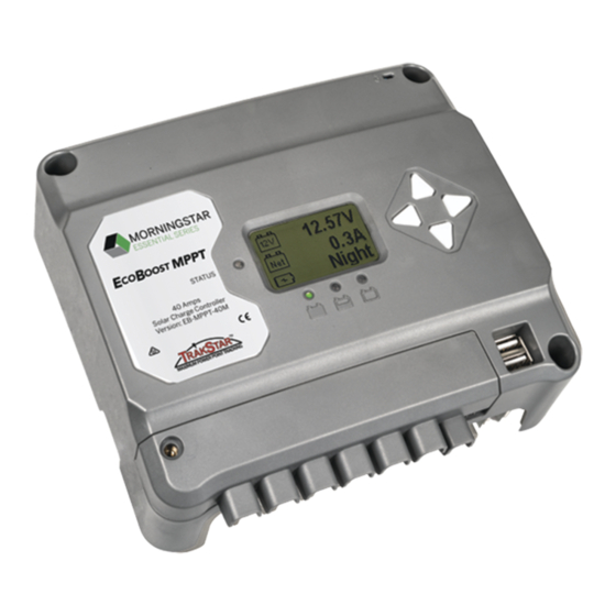
2.1 Merkmale 2 – Kühlkörper/Erdungsschraube (M4-Schraube zur Erdung des Kühlkörpers) Die Merkmale des EcoBoost MPPT sind in Abb. 2-1 unten Aluminium-Kühlkörper (unten) zum Abführen der Wärme des Reglers dargestellt. Dazu wird jedes Merkmal erläutert. (der EcoBoost MPPT ist für mehr Zuverlässigkeit zu 100 % passiv gekühlt) 3 –...
Gehäuse mit einem Flüssig-Akku. die Anzeigewerte des lokalen Temperatursensors stark Akkudämpfe sind entflammbar und greifen die beeinflussen. Ein RTS sorgt für eine optimale Ladeleistung. EcoBoost MPPT Schaltkreise an und zerstören sie. Erdschluss-Schutzeinrichtung (GFPD-150V) ACHTUNG: Geräteschäden Achten Sie auf eine ausreichende Belüftung, Als Sicherheitsmaßnahme entdeckt der GFPD-150V...
• Der EcoBoost MPPT verhindert Rückwärtsleckstrom bei Nacht, eine Sperrdiode ist also im System nicht erforderlich. Abbildung 3.1. DIP-Schalterblock zum Einstellen der Ladeparameter • Der EcoBoost MPPT ist NUR für die Regelung von Solar-(Photovoltaik-)Strom ausgelegt. Der Anschluss an andere Stromquellen wie Windkraftanlagen oder Generatoren lässt den Garantieanspruch verfallen.
Für 24-Volt-Systeme multiplizieren Sie die Spannungseinstellungen mit zwei (2). HINWEIS: Diese Einstellungen sind allgemeine Richtlinien für den Gebrauch nach Ermessen des Betreibers. Der EcoBoost MPPT kann programmiert werden, um eine Vielzahl an Ladeparametern zu erfüllen. Erkundigen Sie sich beim Akkuhersteller nach den optimalen Akkuladeeinstellungen.
3.3 Montage 3.4 Verdrahtung Überprüfen Sie den Regler auf Transportschäden. Montieren Sie den EcoBoost MPPT an einer vertikalen Fläche (4 selbstschneidende Schrauben Nr. 8 liegen bei). Ziehen Sie die Befestigungsschrauben an, aber achten Sie darauf, das Kunststoffgehäuse nicht zu beschädigen. Nicht direkt über einer leicht brennbaren Oberfläche installieren, da der Kühlkörper...
Seite 54
Stellen Sie sicher, dass die höchste temperaturkompensierte Inneren einer Akkuzelle. Sowohl RTS als auch Akku Leerlaufspannung (Voc) und der Ladestrom der Solaranlage werden beschädigt. die Nennwerte der installierten EcoBoost MPPT Version nicht überschreiten. ACHTUNG: Der EcoBoost MPPT verwendet den lokalen Temperatursensor zur Kompensation, wenn der RTS Mehrere Regler können parallel an der gleichen Akkubank...
Seite 55
Sie die Systemleitungen installieren. Schließen Sie die Leitungen der (PV-)Solaranlage bei geöffnetem Solar-Trennschalter an die Solarklemmen des EcoBoost MPPT an. Seien Sie vorsichtig, da die Solaranlage im Sonnenlicht stets Strom produziert. Ein Solar-Trennschalter ist eine praktische Vorrichtung, um die PV-Verbindung bei Bedarf zu unterbrechen.
Seite 56
Schließen Sie keinen Wechselrichter an die Schließen Sie den Akku-Trennschalter, um den Regler Lastanschlüsse des EcoBoost MPPT an. Dies kann einzuschalten. Beobachten Sie den Ladestatus und dann die zu Schäden an der Laststeuerschaltung führen. Ein drei Akku-Ladestatus-LEDs, diese blinken in der Reihenfolge Wechselrichter sollte mit dem Akku verbunden (Gn-Ge-Rt) und bestätigen korrekte Inbetriebnahme.
Seite 57
Wenn das Laden nicht startet, kann das verschiedene Gründe haben: 4.1 TrakStar MPPT-Technologie • der EcoBoost MPPT ist in LVD (rote LED an) Der EcoBoost MPPT nutzt die MPP (Maximum Power Point)- • es gibt einen Kurzschluss im Ladekreis Tracking-Technologie von Morningstar, um maximale Leistung (LEDs blinken Rt/Gn –...
4-Stufen-Ladung sind in den Tabellen 4-1 und 4-2 unten dargestellt. Alle aufgelisteten Spannungseinstellungen sind für Akkus mit Der EcoBoost MPPT verfügt über einen vierstufigen 12 Volt Nennspannung vorgesehen. Für 24-Volt-Akkus Akkuladealgorithmus für schnelles, effizientes und sicheres multiplizieren Sie die Spannungseinstellungen mit zwei (2).
Akkustatus-LED an. Schließen Sie keinen Wechselrichter an die Lastanschlüsse Bootloader fehlgeschlagen: Status-LED blinkt Gn, dann des EcoBoost MPPT an. Dies kann zu Schäden an blinken die Ladezustand-LEDs Gn – Ge und stoppen der Laststeuerschaltung führen. Ein Wechselrichter dauerhaft bei Ge.
Seite 60
2) Rt Ladestatus LED EIN pulsierend, alle 5 Sekunden AUS (auf 0 Ampere falls notwendig), um die Temperatur des ist ein kritischer Fehler, der in der Regel repariert werden Kühlkörpers zu senken. Der EcoBoost MPPT ist für den Betrieb muss. Siehe „Dauerhafte Ladestatus-LED mit Selbsttest bei Nennstrom und maximaler Umgebungstemperatur (Rt-Ge-Gn) SOC-Fehler“, in Abschnitt 5.1.
Plan beigefügt oder in den EcoBoost MPPT Support- 4.6.1 Sollwerteinstellung mit der Messgeräte-Anzeige Dokumenten unter: www.morningstarcorp.com Der EcoBoost MPPT ist verfügbar in Versionen mit und ohne Messgeräte-Anzeige. Das Modell mit Messgerät ermöglicht: 4.6.2 Arbeit mit der Messgeräte-Anzeige • Kundenspezifische Programmierung, einschließlich 4.6.2.1 Verwendung der Richtungstasten und Bedienung/...
4.8 Zusätzliche USB-Ladeanschlüsse Zeitplan Wartungsarbeiten Ziehen Sie die 1) Der EcoBoost MPPT verfügt über zwei USB-A-Schnittstellen, 2 Wochen nach Leistungsanschlüsse wieder die zum Laden kleiner Elektronikgeräte verwendet werden der Installation auf die angegebenen können. Als Energiequelle dient der Systemakku, sodass Drehmomentwerte an.
Keine LED-Anzeige, kein Strom am Gerät. Führt zu wiederhergestellt wurde. Stattdessen zeigt der Regler Grün keinen Schäden am Regler. Korrigieren Sie die fehlerhafte an und stoppt dann bei Gelb. Verdrahtung, um im Normalbetrieb fortzufahren. Last-Kurzschluss Fehlerstatus-LED: Blinkt Rot. Akkustatus-LEDs: Rt/Gn-Ge-Reihenfolge. Fehlersuche EcoBoost MPPT Bedienerhandbuch...
Seite 64
Fall, ist der Fehler wahrscheinlich kritisch. und Wechselrichter Kontaktieren Sie zur Unterstützung einen autorisierten Morningstar-Händler. Wir garantieren, dass der EcoBoost MPPT für einen Zeitraum von Akku-Ladezustand- ZWEI (2) Jahren ab Datum der Auslieferung an den ursprünglichen Fehler Lade-Status-LED LEDs Endanwender frei von Material- und Verarbeitungsfehlern ist.
12/24 V 12/24 V 12/24 V • No hay partes que puedan ser reparadas o reemplazadas nominal por el usuario dentro del EcoBoost MPPT. No desmonte Voltaje máximo del ni intente reparar el controlador. circuito abierto de 120 V 120 V 120 V energía fotovoltaica*...
Seite 68
Seguridad de la batería agua al controlador. • Instale el EcoBoost MPPT en una ubicación que impida un ADVERTENCIA: Una batería puede presentar riesgo contacto casual. El disipador de calor del EcoBoost MPPT de descarga eléctrica o quemaduras debido a una gran...
• Utilice guantes y botas de goma. • Utilice herramientas con mangos aislados y evite colocar Las características del EcoBoost MPPT se muestran en la herramientas u objetos metálicos sobre las baterías. figura 2-1 a continuación. Se proporciona una explicación •...
Disipador de calor de aluminio (debajo) para el controlador Sensor remoto de temperatura (modelo: RTS) (el EcoBoost MPPT se enfría pasivamente al 100 % para una mayor El RTS mide la temperatura de la batería para obtener confiabilidad) una compensación por temperatura precisa;...
Seite 71
ácido de la batería. • El EcoBoost MPPT evita la fuga de corriente inversa por • Utilice herramientas aisladas y evite colocar objetos la noche, de modo que no es necesario un diodo de metálicos cerca de las baterías.
Interruptores 4, 5 y 6: Selección del tipo de batería los parámetros de carga Las opciones preestablecidas de carga de batería del EcoBoost MPPT se muestran en la tabla 3-1 a continuación. Interruptor 1: Carga / Iluminación Todos los ajustes de voltaje listados son para baterías de...
Seite 73
Interruptor 7: Ecualización de la batería Inspeccione el controlador para comprobar si presenta Modo Interruptor 7 daños por envío. Instale el EcoBoost MPPT en una superficie Ecualización manual APAGADO vertical (se incluyen 4 tornillos autorroscantes de #8). Apriete Ecualización automática...
Seite 74
ADVERTENCIA: Riesgo de incendio. Si no está conectado un sensor remoto de temperatura (RTS), use el EcoBoost MPPT dentro de un rango de 3 m de las baterías. Se utilizará la compensación interna por temperatura si el RTS no está conectado. El uso del RTS To properly se recomienda enfáticamente.
Seite 75
Tanto el RTS como la batería se dañarán. • EcoBoost MPPT-20 10 mm PRECAUCIÓN: El EcoBoost MPPT utilizará el sensor • EcoBoost MPPT-30 10 mm local de temperatura para la compensación si •...
Seite 76
NO CIERRE EL BREAKER EN del panel solar (fotovoltaico) a las terminales solares del ESTE MOMENTO. EcoBoost MPPT. Tenga cuidado, ya que el panel solar producirá corriente cada vez que esté expuesto a la luz del sol. Una desconexión solar es una manera conveniente de interrumpir la conexión fotovoltaica cuando sea necesario.
Seite 77
Si la carga no se encendió, esto podría deberse a varias razones: • el EcoBoost MPPT está en desconexión por bajo voltaje (LVD) (indicador LED rojo encendido) • hay un cortocircuito en la carga (LEDs parpadeando rojo/verde – amarillo) El tamaño del fusible o breaker •...
) del panel solar no rebase el voltaje de entrada El banco de baterías debe estar adecuadamente ventilado. máximo de 120 V del EcoBoost MPPT a la temperatura del PRECAUCIÓN: Daños al equipo módulo más baja (en el peor de los casos). La documentación La ecualización incrementa el voltaje de la batería a niveles...
Seite 79
Las opciones preestablecidas de carga de la batería El propósito principal de la función de control de carga es EcoBoost MPPT se muestran en las tablas 4-1 y 4-2 desconectar las cargas del sistema cuando la batería se a continuación. Todos los ajustes de voltaje listados son haya descargado a un estado bajo de carga y reconectar para baterías de 12 voltios nominales.
Rojo Parpadeando Error Sobrecarga solar Continuo Sin indicación LED. El EcoBoost MPPT limitará la corriente Rojo Error crítico (con latido²) de la batería al valor máximo de 20, 30 o 40 A. Un panel solar de gran tamaño no funcionará a potencia pico. El ¹...
La corriente de carga solar se disminuirá El EcoBoost MPPT está disponible en versiones con medidor (a 0 amperios, si fuera necesario) para reducir la temperatura y sin medidor. El modelo con medidor permite: del disipador de calor.
Para los modelos con medidor, vea el folleto del mapa de medición incluido, también disponible en los documentos de apoyo del EcoBoost MPPT en: 1) El EcoBoost MPPT cuenta con dos puertos USB-A para www.morningstarcorp.com uso como fuentes de carga para aparatos electrónicos pequeños.
Cortocircuito de carga adecuadamente. LED de estado de error: Rojo intermitente. Indicadores LED Tabla 4-5. Agenda de mantenimiento de estado de la batería: Secuencia R/V-A (rojo/verde-amarillo). Operación EcoBoost MPPT Manual del operador...
Seite 84
(Voc) excede el valor máximo de así, es muy probable que el error sea crítico. Contacte a un 120 voltios, el panel permanecerá desconectado hasta que distribuidor Morningstar autorizado para obtener ayuda. el Voc caiga con seguridad por debajo del valor máximo. LED de estado de...
DOS (2) años Corriente de 20 Amperios 30 Amperios 40 Amperios a partir de la fecha de envío al usuario final original. Morningstar, a su batería máxima Voltaje máximo del circuito Todos : 120 V discreción, reparará o reemplazará cualquier producto defectuoso.
Seite 86
Sobrecorriente de carga de LVD (no personalizable) Sin límite a menos que V_bat Límite de temperatura del disipador térmico < desconexión por bajo Terminales del sensor remoto de temperatura (RTS) voltaje (LVD) instantánea Especificaciones técnicas EcoBoost MPPT Manual del operador...