Herunterladen Inhalt Inhalt Diese Seite drucken

Werbung

Verfügbare Sprachen

Verfügbare Sprachen

FLH 25M
FLH 60
FLHU 70
FLH 90
Bestell-Nr. : E.G.O.
Montage- und
Gebrauchsanweisung
Installation and
Operating Instructions
Instructions d'installation
et d'utilisation
FD 9203

Werbung

Inhaltsverzeichnis
loading

Inhaltszusammenfassung für Dimplex FLH 25M

  • Seite 1 FLH 25M FLH 60 FLHU 70 Montage- und FLH 90 Gebrauchsanweisung Installation and Operating Instructions Instructions d’installation et d’utilisation Bestell-Nr. : E.G.O. FD 9203...
  • Seite 3: Inhaltsverzeichnis

    5.1 Allgemeine Einbau- und Sicherheitshinweise..................D-2 5.2 Aufbauskizzen ............................D-3 5.3 Montage der Einbauheizung........................D-3 5.4 Hinweise zum Korrosionsschutz......................D-3 5.5 Wasseranschluß des Behälters ......................D-3 5.6 Elektrischer Anschluß ..........................D-4 5.7 Erste Inbetriebnahme ..........................D-4 Kontrolle, Wartung, Pflege ......................D-4 Funktionsstörungen........................D-4 Technische Daten......................... D-5 Elektrischer Anschlussplan ......................D-6 www.dimplex.de...
  • Seite 4: Funktion

    DIN EN usw.) sind auch die Anschlußbedingungen der ört- lichen Elektrizitäts- und Wasserwerke einzuhalten sowie den An- Die Elektro-Einbauheizungen FLH 25M, FLHU 70, FLH 60 und weisungen der Montage- und Bedienungsanleitung Folge zu FLH 90 sind als Hauptheizung für elektrisch beheizte Warmwas- leisten.
  • Seite 5: Einbaulage

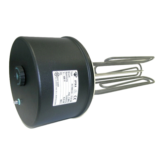
    5.3 Montage der Einbauheizung Einbaulage: Neben den gültigen Gesetztes-Vorschriften sind den Anschluß- bedingungen der örtlichen Elektrizitäts- und Wasserwerke Folge zu leisten. Schutzkappe, Pos. 1, entfernen. Heizflansch, Pos. 2, mit Dichtung, Pos. 3, in den Kessel ein- bauen. Beim Einbau muß das Fühlerschutzrohr des Temperatur- reglers über den Rohrheizkörpern liegen (siehe Einbauhin- weise).
  • Seite 6: Elektrischer Anschluß

    5.7 Erste Inbetriebnahme Eine Sicherheitsventilkombination besteht aus Absperr-, Prüf-, Rücklauf-, Entleerungs- und Sicherheitsventil mit Dehnwasser- ablauf. Dieses Bauteil wird zwischen Kaltwasserzuleitung und ACHTUNG! Kaltwasserzulauf des Speichers in gezeichneter Reihenfolge Vor der elektrischen Inbetriebnahme muß der Speicher mit Wasser gefüllt eingebaut. sein.
  • Seite 7: Technische Daten

    3 ~ 400 umklemmbar auf... FLH 90 3 ~ 400 ACHTUNG! Beim elektrischen Anschluß: Die Flanschheizungen FLH 25M, FLH 60, FLHU 70 und FLH 90 werden mittels Schütz an den Wärmepumpenmanager angeschlossen. Beachten Sie hierbei auch den Klemmenplan des Wärmepumpenmanagers.
  • Seite 8: Elektrischer Anschlussplan

    Elektrischer Anschlussplan FLH 25M – 1/N/PE ~230 V, 50 Hz FLH 60 – 3/PE ~400 V, 50 Hz FLH 90 - 3/PE ~400 V, 50 Hz TR+STB TR+STB 3-polig 3-polig Klemmleiste Klemmleiste FLHU 70 – 3/N/PE ~400 V, 50 Hz...
  • Seite 9 5.3 Installing the flange heater........................E-3 5.4 Notes on corrosion protection......................... E-3 5.5 Water connection of the cylinder ......................E-4 5.6 Electrical connection..........................E-4 5.7 Initial start-up ............................E-4 Inspection, maintenance and service..................E-4 Malfunctions ..........................E-5 Technical data ..........................E-5 Circuit Diagrams..........................E-6 www.dimplex.de...
  • Seite 10: Function

    As main heaters for electrically heated DHW preparation installation and operating instructions. devices, the FLH 25M, FLHU 70, FLH 60 and FLH 90 flange heaters are maintenance-free. In the case of very hard water, In the case of very hard water, we recommend installing a periodic cleaning of the heating elements to remove limescale is standard decalcifying device upstream in the circuit.
  • Seite 11: Mounting Position

    5.3 Installing the flange heater Mounting position: In addition to the national legal regulations, the user must also comply with the connection requirements of the local power and water supply companies. Remove dust cap (pos. 1). Install heating flange (pos.2) with seal (pos. 3) in the boiler. During installation, make sure that the sensor protection tube is above the tubular heating elements (see installation instructions).
  • Seite 12: Water Connection Of The Cylinder

    5.5 Water connection of the Version with contactor control Installation must be carried out by the customer using VDE- cylinder tested contactors which are installed, for example, in a control cabinet or a current distribution board. Separate contactors must The installation, connection and operating instructions for the hot be used for the safety temperature limiter and the temperature water cylinder (boiler), as well as the technical regulations for controller.
  • Seite 13: Malfunctions

    CAUTION! For electrical connection, please note: The FLH 25M, FLH 60, FLHU 70 and FLH 90 flange heaters are connected to the heat pump manager via a contactor. To do this, please also refer to the heat pump manager connection diagram.
  • Seite 14: Circuit Diagrams

    Circuit Diagrams FLH 60 – 3/PE ~400 V, 50 Hz FLH 25M – 1/N/PE ~230 V, 50 Hz FLH 90 - 3/PE ~400 V, 50 Hz TR+STB TR+STB 3-pole 3-pole Terminal strip Terminal strip FLHU 70 – 3/N/PE ~400 V, 50 Hz...
  • Seite 15 Table des matières Objet ...............................F-2 Économies d'énergie ........................F-2 Maniement et réglage de la température..................F-2 Conditions de fonctionnement ....................F-2 Consignes de montage et de sécurité..................F-3 5.1 Consignes générales de montage et de sécurité ................... F-3 5.2 Croquis de la structure..........................F-3 5.3 Montage de la cartouche chauffante ......................
  • Seite 16: Objet

    Comme chauffage principal d'une unité électrique de production d'eau chaude sanitaire, les cartouches chauffantes FLH 25M, Les cartouches chauffantes ne doivent être utilisées que dans FLHU 70, FLH 60 et FLH 90 ne requièrent aucun entretien. En les conditions spécifiées sur la plaque signalétique (pression de présence d'eau fortement calcaire, il peut être en revanche...
  • Seite 17: Consignes De Montage Et De Sécurité

    Consignes de montage 5.2 Croquis de la structure et de sécurité 5.1 Consignes générales de montage et de sécurité En fonctionnement, la cartouche chauffante et la gaine de protection de la sonde doivent être entièrement immergées dans l'eau. Rien ne doit empêcher les courants d'eau entraînés par les variations de température.
  • Seite 18: Remarques Relatives À La Protection Contre La Corrosion

    5.6 Branchements électriques protection contre la corrosion ATTENTION ! Les réservoirs émaillés de fabrication autre que Dimplex doivent Pour des raisons de garantie, seul un personnel autorisé et compétent être dotés d'une protection par anode conformément aux est habilité à effectuer le montage et la mise en service initiale de la données du fabricant.
  • Seite 19: Inspections, Maintenance Et Entretien

    Inspections, maintenance et entretien En présence d’eau fortement calcaire, il convient de confier à un spécialiste  le décapage du tartre qui s'est déposé sur la paroi interne  et dans le réservoir au bout de 1 à 2 ans de service. Le nettoyage réalisé...
  • Seite 20: Caractéristiques Techniques

    FLH 90 3 ~ 400 ATTENTION ! Branchements électriques Les cartouches chauffantes FLH 25M, FLH 60, FLHU 70 et FLH 90 sont raccordées par contacteur au gestionnaire de pompe à chaleur. Tenir compte du schéma de branchement du gestionnaire.
  • Seite 21: Schémas Électriques

    Schémas électriques FLH 60 – 3/PE ~400 V, 50 Hz FLH 25M – 1/N/PE ~230 V, 50 Hz FLH 90 - 3/PE ~400 V, 50 Hz TR+STB TR+STB à 3 pôles à 3 pôles Bornier Bornier FLHU 70 – 3/N/PE ~400 V, 50 Hz...
  • Seite 24 GDD GmbH Irrtümer und Änderungen vorbehalten. Subject to alterations and errors. Sous réserve d’erreurs et modifications. D-95326 Kulmbach...

Diese Anleitung auch für:

Flh 60Flh 90Flhu 70

Inhaltsverzeichnis