Chauvin Arnoux C.A 5231 Bedienungsanleitung
Vorschau ausblenden
Andere Handbücher für C.A 5231:
- Bedienungsanleitung (117 Seiten) ,
- Bedienungsanleitung (119 Seiten)
Inhaltsverzeichnis
Werbung
Verfügbare Sprachen
Verfügbare Sprachen
Quicklinks
Werbung
Kapitel
Inhaltsverzeichnis

Verwandte Anleitungen für Chauvin Arnoux C.A 5231


Inhaltszusammenfassung für Chauvin Arnoux C.A 5231
- Seite 1 Français C.A 5231 MULTIMÈTRE MULTIMETER MULTIMETER MULTIMETRO MULTIMETRO FRANÇAIS Notice de fonctionnement E NG LIS H User’s manual DEUTSCH Bedienungsanleitung ITALI ANO Manuale d’uso ESP AŇOL Manual de instrucciones 1 - 117...
-
Seite 2: Précautions D'emploi
Français PRÉCAUTIONS D’EMPLOI Cet appareil est conforme à la norme de sécurité IEC 61010-1 pour des tensions de 1000 V en catégorie III ou 600 V en catégorie IV à une altitude inférieure à 2000 m et en intérieur, avec un degré de pollution au plus égal à 2. Le non-respect des consignes de sécurité... - Seite 3 Français CATÉGORIES DE MESURE Définition des catégories de mesure selon la norme IEC 61010-1 : CAT I : Circuits non reliés directement au réseau et spécialement protégés. Exemple: circuits électroniques protégés. CAT II : Circuits directement branchés à l'installation basse tension.
- Seite 4 Français Vous venez d’acquérir un multimètre C.A 5231 et nous vous remercions de votre confiance. Pour obtenir le meilleur service de votre appareil : Lisez attentivement cette notice de fonctionnement ; Respectez les précautions d’emploi. Signification des symboles utilisés sur l’appareil : Risque de danger.
-
Seite 5: Inhaltsverzeichnis
Français SOMMAIRE 1. PRÉSENTATION ................6 1.1 L’AFFICHEUR ................7 1.2 LES TOUCHES ................9 1.3 LE COMMUTATEUR ..............10 1.4 LES BORNES ................11 2. UTILISATION ................11 2.1 PREMIÈRE UTILISATION ............11 2.2 MISE EN SERVICE DU MULTIMÈTRE ........12 2.3 ARRÊT DU MULTIMÈTRE ............ -
Seite 6: Présentation
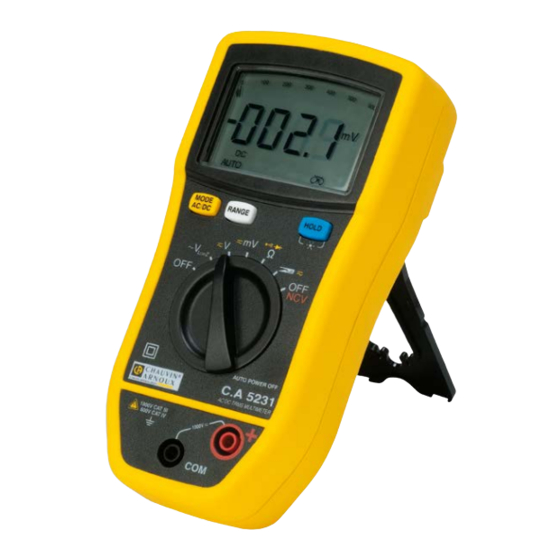
Français 1. PRÉSENTATION Le C.A 5231 est un multimètre numérique TRMS, portatif et autonome, spécialement conçu pour regrouper en un seul appareil les différentes fonctions de mesure des grandeurs électriques suivantes : Voltmètre en courant alternatif à basse impédance d'entrée (mesure de tensions en électricité... -
Seite 7: L'afficheur
Français Voir § Rep. Désignation Afficheur Touches de fonction Commutateur Bornes 1.1 L’AFFICHEUR L’afficheur permet : Un affichage de type analogique du paramètre mesuré grâce au bargraphe, associé à l’affichage digital sur 6000 points. Une lecture confortable des informations grâce au rétro- éclairage de l’écran. - Seite 8 Français Voir § Rep. Fonction Bargraphe Affichage (valeurs et unités de mesure) Nature de la mesure (alternatif ou continu) 3.2.1 Mode automatique de sélection du calibre de 3.2.2 mesure (Autorange) Indicateur de pile usagée Test de continuité sonore 3.1.3 Test de diode 3.1.4 HOLD Mode Non Permanent : arrêt automatique de...
-
Seite 9: Les Touches
Français Mode Non Permanent (arrêt automatique activé) Indicateur de pile usagée 1.1.2 Dépassement des capacités de mesure (O.L.) Le symbole O.L. (Over Load) s’affiche quand le signal mesuré dépasse les capacités du calibre de l’appareil. 1.1.3 Changement automatique du calibre de mesure (Autorange) Le symbole AUTO sur l’afficheur indique que l’appareil change automatiquement le calibre de mesure pour effectuer la... -
Seite 10: Le Commutateur
Français 1.3 LE COMMUTATEUR Le commutateur possède sept positions. Les fonctions sont décrites dans le tableau ci-dessous : Figure 4 : le commutateur Rep. Fonction Voir § Mode OFF – Arrêt du multimètre Mesure de tension alternative (AC) en basse 3.1.1 impédance (V LowZ... -
Seite 11: Les Bornes
Français 1.4 LES BORNES Les bornes sont utilisées comme suit : Figure 5 : les bornes Rep. Fonction Borne point froid (COM) Borne point chaud (+) 2. UTILISATION 2.1 PREMIÈRE UTILISATION Placez la pile fournie avec l’appareil comme suit : A l’aide d’un tournevis, dévissez les quatre vis a, b, c et d de la trappe (rep.1) situées à... -
Seite 12: Mise En Service Du Multimètre
Français 2.2 MISE EN SERVICE DU MULTIMÈTRE Le commutateur est sur la position . Tournez le commutateur vers la fonction de votre choix. L’ensemble des segments de l’afficheur apparaît pendant quelques secondes (voir figure 2, § 1.1) puis l’écran de la fonction choisie s’affiche. Le multimètre est alors prêt pour les mesures. -
Seite 13: Fonctions
Français 3. FONCTIONS 3.1 FONCTIONS DU COMMUTATEUR Pour accéder aux fonctions du commutateur, placez le commutateur sur 3.1.1 Mesure de tension L’appareil mesure : La tension alternative en basse impédance d’entrée (V LOWZ La tension continue (DC) ; ... -
Seite 14: Test De Diode
Français Placez les pointes de touche aux bornes du composant ou du circuit à mesurer ; La valeur de la résistance mesurée s’affiche à l’écran. 3.1.3 Test de continuité avec Buzzer Attention : toutes les mesures de continuité doivent se faire hors-tension. - Seite 15 Français Branchez le cordon noir sur la borne COM et le cordon rouge sur « + » ; Placez les pointes de touche aux bornes du composant ; Sens direct La valeur de la tension développée s’affiche à l’écran. 3.1.5 Mesure d’intensité...
-
Seite 16: Fonctions Des Touches
Français 3.1.6 Non Contact Voltage NCV Positionnez le commutateur sur Approchez le C.A 5231 (zone de détection NCV) du (des) conducteur(s) potentiellement sous tension (présence de phase) ; Si présence de tension réseau de 230V (modèle Europe), le rétro-éclairage s’allume en rouge ; dans le cas contraire, il reste éteint. -
Seite 17: Caractéristiques
Français Chaque appui … … permet de changer manuellement le calibre court de mesure (étendue et résolution). long de revenir en mode Auto-range. (> 2 sec) Remarque : les modes test de continuité et test de diode ne sont pas Auto-range. 3.2.3 Touche Cette touche permet de maintenir l’affichage de la valeur... -
Seite 18: Caractéristiques Aux Conditions De Référence
Français 4.2 CARACTÉRISTIQUES AUX CONDITIONS DE RÉFÉRENCE L’incertitude est exprimée en x % de la lecture + y point(s), de 10% à 100% de chaque gamme de mesure. 4.2.1 Tensions continues L’impédance d’entrée est de 10MΩ. mV DC Gamme Résolution Incertitude (±) 60 mV... - Seite 19 Français V AC True RMS Incertitude (±) Incertitude (±) Gamme Résolution 40 Hz à 60 Hz 60 Hz à 1 kHz 0,001 V 60 V 0,01 V 2,5% + 3 pts 2% + 3 pts 600 V 0,1 V 1000 V 4.2.3 Tensions alternatives en basse impédance (V...
-
Seite 20: Test De Continuité
Français 4.2.5 Test de continuité Courant Gamme Résolution Incertitude de mesure Signal sonore 600 Ω 0,1 Ω < 0,35 mA garanti <20 Ω 4.2.6 Test de diode Incertitude Tension en Courant Gamme Résolution circuit ouvert de mesure (±) 2,8 V 0,001 V 2 % + 5 pts <... -
Seite 21: Alimentation
Français 4.5 ALIMENTATION Alimentation : Pile 9 V LF22/6LR61 Autonomie : > 100 heures à température ambiante Délai d’auto extinction : Après 15 minutes de non utilisation 4.6 CONFORMITÉS AUX NORMES INTERNATIONALES Sécurité électrique : Application des règles de sécurité selon la norme EN 61010-1. -
Seite 22: Maintenance
Français 5. MAINTENANCE Pour la maintenance, utilisez seulement les pièces de rechange qui ont été spécifiées. 5.1 NETTOYAGE Déconnectez tout cordon de l’appareil et positionnez le commutateur sur Utilisez chiffon doux, légèrement imbibé d’eau savonneuse. Rincez avec un chiffon humide. ... -
Seite 23: Réparation
Français 5.4 RÉPARATION Pour les réparations sous garantie et hors garantie, contactez votre agence commerciale Chauvin Arnoux la plus proche ou votre centre technique régional Manumesure qui établira un dossier de retour et vous communiquera la procédure à suivre. Coordonnées disponibles sur notre site : http://www.chauvin-arnoux.com... -
Seite 24: Pour Commander
Français 7. POUR COMMANDER Le C.A 5231 Le multimètre est livré avec : • 1 paire de cordons pointe de touche, rouge et noir • 1 pile 9 V alcaline • la notice de fonctionnement 5 langues. C.A 5231 P01196731 ... -
Seite 25: Precautions For Use
English PRECAUTIONS FOR USE This device complies with safety standard IEC-61010-1 for voltages up to 1000V in category III or 600V in category IV, at an altitude below 2000m, indoors, with a pollution level of not more than 2. Failure to observe the safety instructions may cause an electric shock, fire, explosion, or destruction of the instrument and of the installations. -
Seite 26: Measurement Categories
English MEASUREMENT CATEGORIES Definitions of the measurement categories according to standard IEC 61010-1: CAT I: Circuits not directly connected to the network and specially protected. Example: protected electronic circuits. CAT II: Circuits directly connected to the low-voltage installation. Example: power supply to household electrical appliances and portable tools. - Seite 27 English Thank you for purchasing a C.A. 5231 multimeter. For best results from your device: Read this user manual attentively; Observe the precautions for its use. Meaning of symbols used on the instrument: Risk of danger. The operator agrees to refer to these instructions whenever this danger symbol appears.
- Seite 28 English CONTENTS 1. PRESENTATION ................ 29 1.1 DISPLAY UNIT ................30 1.2 THE KEYS ..................32 1.3 THE SWITCH ................33 1.4 THE TERMINALS ................ 34 2. USE 34 2.1 FIRST USE ................... 34 2.2 POWERING UP THE MULTIMETER ......... 35 2.3 POWERING DOWN THE MULTIMETER ........
-
Seite 29: Presentation
English 1. PRESENTATION The C.A 5231 is a TRMS digital multimeter, specially designed to combine in a single instrument the various functions and measurements of the following electrical quantities: voltmeter with input impedance (voltage measurements in the fields of electricity and electrical engineering);... -
Seite 30: Display Unit
English S ee § Item Designation Display unit Function keys Switch Terminals 1.1 DISPLAY UNIT The display unit allows : An analog display of the parameter measured, in the form of a bargraph, associated with a 6,000-point digital display. ... - Seite 31 English S ee § Item Function Bargraph Display (values and units of measurement) Nature of measurement (AC or DC) 3.2.1 Automatic measurement range selection 3.2.2 mode (Autorange) Low battery indicator Audible continuity test 3.1.3 Diode test 3.1.4 HOLD Non-Permanent Mode : automatic switching 3.2.1 off of the device activated 1.1.1...
-
Seite 32: The Keys
English Mode Non Permanent (automatic switching off activated) Low battery indicator 1.1.2 Overshoot of measurement capabilities (O.L.) The O.L. (Over Load) symbol is displayed when the signal measured exceeds the range of the device. 1.1.3 Automatic change of measurement range (Autorange) The AUTO symbol on the display unit indicates that the instrument automatically changes the measurement range to... -
Seite 33: The Switch
English 1.3 THE SWITCH The switch has seven positions. The functions are described in the table below: Figure 4: the switch Item Function See § OFF mode – Powers down the multimeter Low-impedance AC voltage measurement 3.1.1 LowZ AC or DC voltage measurement (V) 3.1.1 AC or DC voltage measurement (mV) 3.1.1... -
Seite 34: The Terminals
English 1.4 THE TERMINALS The terminals are used as follows: Figure 5: the terminals Item Function Cold point terminal (COM) Hot point terminal (+) 2. USE 2.1 FIRST USE Insert the battery provided with the instrument as folows: Using a screwdriver, unscrew the four screws (a, b, c, and d) holding the cover (item 1) on the back of the housing;... -
Seite 35: Powering Up The Multimeter
English 2.2 POWERING UP THE MULTIMETER The switch is set to . Turn the switch to the function of your choice. All segments of the display unit light for a few seconds (see Figure 2, § 1.1) the screen corresponding to the chosen function then appears. -
Seite 36: Functions
English 3. FUNCTIONS 3.1 FUNCTIONS OF THE SWITCH To access to the functions of the switch, set the switch to 3.1.1 Voltage measurment The instrument measures: The AC voltage at low input impedance (V LOWZ Direct voltages (DC) ; ... -
Seite 37: Continuity Test With Buzzer
English Place the contact tips on the terminals of the component or circuit to be measured; The measured resistance is displayed on screen. 3.1.3 Continuity test with buzzer Attention: all continuity measurements must be made in the absence of any voltage To test electrical continuity, proceed as follows: Set the switch to Press... - Seite 38 English Connect the black lead to the COM terminal and the red lead to « + » ; Place the contact tips on the terminals of the component ; Forward direction The voltage across the terminals of the component is displayed on screen.
-
Seite 39: Functions Of The Keys
3.1.6 Non Contact Voltage NCV Set the switch to Move the C.A 5231 (NCV detection zone) close to the potentially live conductor(s) (presence of phase) ; If a network voltage of 230V is present (Europe model), the back-lighting lights red, otherwise, it remains off. -
Seite 40: Characteristics
English Each press of … serves to this length … to change the measurement range short manually (span and resolution). long to return to Auto-range mode. (> 2 sec) Remark: the continuity test and diode test modes are not Auto-range; 3.2.3 This key is used to hold the display of the measured value, and to activate/deactivate the backlighting of the screen. -
Seite 41: Characteristics At The Reference Conditions
English 4.2 CHARACTERISTICS AT THE REFERENCE CONDITIONS The uncertainty is expressed in the form x% of the reading + y counts, from 10% to 100% of each measurement range. 4.2.1 Direct voltages The input impredance is 10MΩ. mV DC Range Resolution Uncertainty (±) - Seite 42 English V AC True RMS Uncertainty (±) Uncertainty (±) Range Resolution 45 Hz à 60 Hz 60 Hz to 1 kHz 0.001 V 60 V 0.01 V 2 % + 3 cts 2.5 % + 3 cts 600 V 0.1 V 1000 V 4.2.3...
-
Seite 43: Continuity Test
English 4.2.5 Continuity test Measurement Range Resolution Uncertainty current Audible signal 600 Ω 0,1 Ω < 0.35 mA < 20 Ω 4.2.6 Diode test Uncertainty Open-circuit Measurement Range Resolution voltages current (±) 2.8 V 0.001 V 2 % + 5 cts <... -
Seite 44: Power Suplly
English 4.5 POWER SUPLLY Power supply : Pile 9 V LF22/6LR61 Battery life : > 100 heures à température ambiante Automatic switching-off 15 minutes of non-use time : 4.6 COMPLIANCE WITH INTERNATIONAL STANDARDS Application of safety rules as per standard Electrical safety : EN-61010-1 - 1000V CAT-III - 600V CAT- IV. -
Seite 45: Maintenance
This instrument should be checked at least once a year. For checking and calibration, contact one of our accredited metrology laboratories (information and contact details available on request), at our Chauvin Arnoux subsidiary or the branch in your country. 5.4 REPAIR For all repairs before or after expiry of warranty, please return the device to your distributor. -
Seite 46: Warranty
English 6. WARRANTY Except as otherwise stated, our warranty is valid for twelve months starting from the date on which the equipment was sold. Extract from our General Conditions of Sale provided on request. The warranty does not apply in the following cases: ... -
Seite 47: To Order
English 7. TO ORDER The C.A 5231 The multimeter is delivered with • 1 pair of leads, red and black • 1 9 V alkaline battery • the user manual in 5 languages C.A 5231 P01196731 Accessories MINI 03 clamp (1 A - 100 A AC) P01105103Z MN 15 clamp(0.5 A –... -
Seite 48: Bedienungshinweise
Deutsch BEDIENUNGSHINWEISE Die Spannungs- und Überspannungskategorien dieses Geräts [1000 Messkategorie III, Messkategorie entsprechen der Sicherheitsnorm IEC 61010-1 bzw. in Innenräumen, bis zu einem Verschmutzungsgrad 2 und auf bis zu 2000 m Höhe. Sicherheitsanweisungen müssen unbedingt beachtet werden, weil sonst Stoßspannung, Brand, Explosion oder Zerstörung des Geräts und der Anlagen drohen. - Seite 49 Deutsch MESSKATEGORIE Definition der Messkategorien gemäß IEC 61010-1: CAT I: Stromkreise, die nicht direkt mit dem Stromnetz verbunden sind oder geschützt sind. Beispiel: geschützte Stromkreise. CAT II: Stromkreise an Niederspannungsanlagen. Beispiel: Stromversorgung Haushaltsgeräten oder tragbaren Elektrowerkzeugen. CAT III: Stromversorgungskreise innerhalb der Haus- oder Gebäudeinstallation.
- Seite 50 Deutsch Sie haben ein C.A. 5231 Multimeter erstanden, wir danken Ihnen für Ihr Vertrauen. Für die Erlangung eines optimalen Betriebsverhaltens Ihres Gerätes: Lesen Sie bitte diese Betriebsanleitung aufmerksam durch und; Beachten Sie bitte die Anwendungshinweise. Bedeutung der Gerätesymbole: Gefahr! Sobald dieses Gefahrenzeichen auftritt, ist der Bediener verpflichtet, die Anleitung zu Rate zu ziehen.
- Seite 51 Deutsch INHALT 1. VORSTELLUNG ................. 52 1.1 ANZEIGE ..................53 1.2 TASTEN ..................55 1.3 SCHALTER .................. 56 1.4 BUCHSEN ..................57 2. VERWENDUNG ................57 2.1 ERSTE SCHRITTE ..............57 2.2 MULTIMETER-INBETRIEBNAHME ........... 58 2.3 MULTIMETER ABSCHALTEN............ 58 2.4 DER STANDBÜGEL ..............58 3.
-
Seite 52: Vorstellung
AC- und/oder DC-Voltmeter bei hoher Eingangsimpedanz (Spannungsmessen in Elektronik); Ohmmeter; Durchgangsprüfung mit Summer; Diodenprüfung; Amperemeter (Messung mit Strommesszange); Berührungsfreie Erfassung Netzspannung (NCV- Funktion Vorhandsein von Phasen). NCV-Schwellzone Abb. 1 : Multimeter C.A 5231 52 - 117... -
Seite 53: Anzeige
Deutsch S iehe Abs . § Bezeichnung Anzeige Funktionstaten Drehschalter Buchsen 1.1 ANZEIGE Die Anzeige ermöglicht: Eine Analog-Anzeige dank einer Balkenanzeige, sowie eine Digitalanzeige mit 6000 Digits. Ein bequemes Ablesen der Informationen dank Hintergrundbeleuchtung der Anzeige. Abb. 2 : Anzeige 53 - 117... -
Seite 54: Anzeigesymbole
Deutsch S iehe Abs . § Funktion Balkenanzeige Anzeige (Werte und Messeinheiten) Messart (AC oder DC) 3.2.1 Automatische Messbereichseinstellung 3.2.2 (Autorange) Anzeige bei geringem Batterieladestand Akustische Durchgangsprüfung 3.1.3 Diodenprüfung 3.1.4 HOLD Nicht-Dauerbetriebmodus: 3.2.1 Stromsparmodus (autom. Abschalten des Gerätes) aktiviert 1.1.1 Anzeigesymbole Folgende Anzeigesymbole werden verwendet: Symbole... -
Seite 55: Überschreitung Der Messkapazität (O.l)
Deutsch M Nicht-Dauerbetriebsmodus (Abschaltautomatik) Anzeige bei geringem Batterieladestand 1.1.2 Überschreitung der Messkapazität (O.L) Das Symbol O.L (Over Load) erscheint auf der Anzeige, wenn Messsignal Messbereichkapazität Gerätes übersteigt. 1.1.3 Auto-Range-Modus (Autorange) Das Symbol AUTO bedeutet, dass das Gerät den Messbereich automatisch festlegt. Der Messbereich kann manuell mit Drücken der Taste geändert werden (siehe Abs. -
Seite 56: Schalter
Deutsch 1.3 SCHALTER Drehschalter mit sieben Stellungen. Die Funktionen werden in der Tabelle unten beschrieben: Abb. 4 : Schalter Siehe Funktion Abs. OFF – Multimeter ausschalten Messen der Wechselspannung (AC) bei 3.1.1 niedriger Impedanz (V LowZ Messen der AC- oder DC-Spannung (V) 3.1.1 Messen der AC- oder DC-Spannung (mV) 3.1.1... -
Seite 57: Buchsen
Deutsch 1.4 BUCHSEN Verwendung der einzelnen Buchsen: Abb. 5 : Buchsen Funktion Buchse Kaltpunkt (COM) Buchse Heißpunkt (+) 2. VERWENDUNG 2.1 ERSTE SCHRITTE Legen Sie die mitgelieferte Batterie so ein: Mit einem Schraubendreher die vier Schrauben a, b, c und d des Batteriefachdeckels (Nr. 1) hinten am Gehäuse lösen;... -
Seite 58: Multimeter-Inbetriebnahme
Deutsch 2.2 MULTIMETER-INBETRIEBNAHME Der Schalter steht auf . Drehen Sie den Schalter auf die gewünschte Funktion. Kurz blinken alle Anzeigesegmente auf (siehe Abb. 2, S. 1.1), dann wird die gewählte Funktion angezeigt. Das Gerät ist nun messbereit. 2.3 MULTIMETER ABSCHALTEN Das Multimeter wird manuell mit dem Drehschalter abgeschaltet (Schalter auf , drehen), bzw. -
Seite 59: Funktionen
Deutsch 3. FUNKTIONEN 3.1 DREHSCHALTERFUNKTIONEN Direkter Zugriff auf die Funktionen oder über die jeweilige. Drehschalterposition. 3.1.1 Spannungsmessungen Das Gerät misst: Die Wechselspannung in niedriger Eingangsimpedanz (V LowZ DC-Spannung; AC-Spannung; Zum Spannungsmessen geht man wie folgt vor: Stellen Sie den Drehschalter auf oder ist das Gerät nur im AC-Modus. -
Seite 60: Durchgangsprüfung Mit Summer
Deutsch Die Prüfspitzen an den Buchsen des Prüfkreises bzw. Prüflings anbringen; Der Wert des gemessenen Widerstands erscheint auf der Anzeige. 3.1.3 Durchgangsprüfung mit Summer Achtung Alle Durchgangsmessungen müssen außer Spannung erfolgen. Für die Durchgangsprüfung geht man wie folgt vor: Stellen Sie den Drehschalter auf Drücken Sie auf . - Seite 61 Deutsch schwarzen Prüfdraht Buchse anschließen, den roten Prüfdraht an „+“ ; Legen Sie die Prüfspitzen an die Komponentenbuchsen; Durchlass Der Wert der Lastspannung erscheint auf der Anzeige. 3.1.5 Stromstärkemessung mit Strommesszange Stellen Sie den Drehschalter auf Wählen Sie AC oder DC durch Drücken der Taste Das Gerät ist auf AC-Modus voreingestellt.
-
Seite 62: Tastenfunktionen
Deutsch 3.1.6 Non Contact Voltage NCV Stellen Sie den Drehschalter auf Nähern Sie das C.A 5231 (Erkennungszone NCV) dem/den möglicherweise spannungsführenden Leiter/n (Vorhandensein von Phasen); Beim Vorhandensein von 230V Netzspannung (für Europa-Modell), leuchtet die Hintergrundbeleuchtung rot auf; andernfalls bleibt sie ausgeschaltet. -
Seite 63: Eigenschaften
Deutsch Mit jedem … geschieht Folgendes: Tastendruck … Manuelle Änderung des kurz Messbereichs (Bereich und Auflösung). lang Zurück zum Auto-Range-Modus. (> 2 sec) Hinweis : Für Durchgangsprüfungs- Diodentestmodus gibt es kein Auto-Range. 3.2.3 Taste Mit dieser Taste kann die Anzeige des gemessenen Werts gehalten werden, und außerdem die Hintergrundbeleuchtung der Anzeige aktiviert bzw. -
Seite 64: Eigenschaften Zu Den Referenzbedingungen
Deutsch 4.2 EIGENSCHAFTEN ZU DEN REFERENZBEDINGUNGEN Abweichungen werden in x% für den Leswert und y Punkte angegeben, 10% bis 100% jeder bereich gegeben. 4.2.1 DC-Spannung Die Eingangsimpedanz ist 10MΩ. mV DC Bereich Auflösung Abweichungen (±) 60 mV 0,01 mV 1 % + 12 pkte 600 mV 0,1 mV... - Seite 65 Deutsch V AC True RMS Abweichungen (±) Abweichungen (±) Bereich Auflösung 45 Hz bis 60 Hz 60 Hz bis 1 kHz 0,001 V 60 V 0,01 V 2 % + 3 pkte 2,5 % + 3 pkte 600 V 0,1 V 1000 V 4.2.3...
-
Seite 66: Durchgangsprüfung
Deutsch 4.2.5 Durchgangsprüfung Bereich Auflösung Abweichungen Messstrom 600 Ω 0,1 Ω Signallaut <20 Ω < 0,35 mA 4.2.6 Diodenprüfung Abweichungen Bereich Auflösung Leerspannung Messstrom (±) 2,8 V 0,001 V 2 % + 5 pkte < 2,8 V < 0,9 mA 4.2.7 Wechsel- / Gleichströme ... -
Seite 67: Stromversorgung
Deutsch 4.5 STROMVERSORGUNG Stromversorgung : Akku 9 V LF22/6LR61 Betriebsautonomie : > 100 Stunden bei Umgebungstemperatur Stromsparmodus : Nach 15 Min. Inaktivität 4.6 KONFORMITÄT MIT INTERNATIONALEN NORMEN Elektrische Anwendung der Sicherheitsvorschriften Sicherheit : gemäß EN 61010-1 - 1000V CAT III - 600V CAT IV. -
Seite 68: Wartung
Es wird mindestens eine einmal jährlich durchgeführte Überprüfung dieses Gerätes empfohlen. Für Überprüfung und Kalibrierung wenden Sie sich bitte an unsere zugelassenen Messlabors (Auskunft und Adressen auf Anfrage), bzw. an die Chauvin Arnoux Niederlassung oder den Händler in Ihrem Land. 68 - 117... -
Seite 69: Reparatur
Deutsch 5.4 REPARATUR Senden Sie das Gerät bei Reparaturen innerhalb und außerhalb der Garantie an die Chauvin Arnoux Niederlassung oder Ihren Händler zurück. 6. GARANTIE Ausnahme ausdrücklichen anders lautenden Vereinbarungen Garantiezeit zwölf Monate Bereitstellung des Geräts beim Kunden. Auszug aus den Allgemeinen Geschäftsbedingungen (Gesamttext auf Anfrage). -
Seite 70: Bestellangaben
Deutsch 7. BESTELLANGABEN C.A 5231 Lieferumfang des Multimeters: • 1 Satz Prüfdrähte, rot und schwarz • 1 Alkali-Akku 9V • 1 Bedienungsanleitung in 5 Sprachen C.A 5231 P01196731 Zubehör Zange MINI 03 (1 A - 100 A AC) - Seite 71 Italiano PRECAUZIONI D’USO Questo strumento è conforme alla norma di sicurezza IEC-61010-1 per tensioni di 1000 V in categoria III o 600 V in categoria IV ad un’altitudine inferiore a 2000 m e all’interno, con un grado d’inquinamento pari a 2 (Massimo). Il mancato rispetto delle consegne di sicurezza può...
- Seite 72 Italiano CATEGORIE DI MISURA Definizione delle categorie di misura secondo la norma IEC- 61010-1: Circuiti collegati direttamente alla rete particolarmente protetti. Esempio: circuiti elettronici protetti. CAT II: Circuiti direttamente collegati all'impianto a bassa tensione. Esempio: alimentazione d’apparecchi elettrodomestici d’attrezzatura portatile. CAT III: Circuiti d’alimentazione nell'impianto dell’edificio.
- Seite 73 Italiano Avete appena acquistato un multimetro C.A. 5231 e vi ringraziamo della vostra fiducia. Per ottenere dal vostro apparecchio le migliori prestazioni: Leggere attentamente questo libretto d’istruzioni, Rispettare le precauzioni d’uso. Significato dei simboli utilizzati sull’apparecchio : Rischio di pericolo. L'operatore s'impegna a consultare il presente libretto ogni volta che incontra questo simbolo di pericolo.
- Seite 74 Italiano INDICE 1. PRESENTAZIONE ..............75 1.1 IL DISPLAY .................. 76 1.2 I TASTI ..................78 1.3 IL COMMUTATORE ..............79 1.4 I MORSETTI ................. 80 2. UTILIZZO..................80 2.1 PRIMO UTILIZZO ................ 80 2.2 MESSA IN SERVIZIO DEL MULTIMETRO ....... 81 2.3 ARRESTO DEL MULTIMETRO ..........
-
Seite 75: Presentazione
Italiano 1. PRESENTAZIONE C.A 5231 è un multimetro digitale TRMS, portatile e autonomo, appositamente progettato per raggruppare in un solo strumento le varie funzioni di misura delle seguenti grandezze elettriche: Voltmetro in corrente alternata a bassa impedenza d'entrata (misura di tensioni d’elettricità e d’elettrotecnica);... -
Seite 76: Il Display
Italiano C ons ultare § Rif. Descrizione Display Tasti di funzione Commutatore Morsetti 1.1 IL DISPLAY Il display permette : Una visualizzazione di tipo analogico del parametro misurato grazie al bargraph, associato alla visualizzazione digitale su 6000 punti. Una confortevole lettura delle informazioni grazie alla retroilluminazione dello schermo. - Seite 77 Italiano C ons ultare § Rif. Funzione Bargraph Visualizzazione (valori e delle unità di misura) Natura della misura (alternata o continua) 3.2.1 Modo automatico di selezione del calibro di 3.2.2 misura (Autorange) Indicatore di pila usata 3.1.3 Test di continuità sonoraTest diodo 3.1.4 HOLD Modo Non Permanente: arresto automatico...
-
Seite 78: I Tasti
Italiano Modo Non Permanente (arresto automatico attivato) Indicatore di pila usata 1.1.2 Superamento delle capacità di misura (O.L) Il simbolo O.L (Over Load) appare quando il segnale misurato supera le capacità del calibro dello strumento. 1.1.3 Cambio automatico del calibro di misura (Autorange) Il simbolo AUTO sul display indica che lo strumento cambia automaticamente il calibro di misura per effettuare la misura. -
Seite 79: Il Commutatore
Italiano 1.3 IL COMMUTATORE Il commutatore possiede sette posizioni. Le funzioni sono descritte nella seguente tabella : Figura 4 : il commutatore Rif. Consultare Descrizione § Modo OFF – Arresto del multimetro Misura di tensione alternata (AC) in bassa 3.1.1 impedenza (V LowZ Misura di tensione in AC o in DC (V) -
Seite 80: I Morsetti
Italiano 1.4 I MORSETTI I morsetti sono utilizzati come segue: Figura 5 : i morsetti Rif. Funzione Morsetto punto freddo (COM) Morsetto punto caldo (+) 2. UTILIZZO 2.1 PRIMO UTILIZZO Inserite la pila fornita con lo strumento come segue: Mediante un cacciavite, svitate le quattro viti a, b, c e d dello sportello (rif. -
Seite 81: Messa In Servizio Del Multimetro
Italiano 2.2 MESSA IN SERVIZIO DEL MULTIMETRO Il commutatore è posizionato su . Ruotate il commutatore verso la funzione di vostra scelta. L'insieme dei segmenti del display appare per alcuni secondi (consultare Figura 2, §1.1) e poi appare sullo schermo la funzione selezionata. Il multimetro è... -
Seite 82: Funzioni
Italiano 3. FUNZIONI 3.1 FUNZIONI DEL COMMUTATORE Per accedere alle funzioni oppure posizionate il commutatore sulla funzione scelta. 3.1.1 Misura di tensione Lo strumento misura : la tensione alternata in bassa impedenza d'ingresso (V LowZ la tensione continua (DC); ... -
Seite 83: Test Diodo
Italiano Posizionate le punte di contatto sui morsetti del componente o del circuito da misurare; Il valore della resistenza misurata si visualizza allo schermo. 3.1.3 Test di continuità con cicalino Attenzione : tutte le misure di continuità vanno effettuate fuori tensione. - Seite 84 Italiano Allacciate il cordone nero al morsetto COM e il cordone rosso a « + » ; Posizionate le punte di contatto sui morsetti del componente ; Senso diretto Il valore della tensione sviluppata si visualizza allo schermo. 3.1.5 Misura d’intensità con Pinza Amperometrica Posizionate il commutatore su Selezionate AC o DC premendo .
-
Seite 85: Funzioni Dei Tasti
Italiano 3.1.6 Non Contact Voltage NCV Posizionate il commutatore su Avvicinate il C.A5231 (zona di rivelazione NCV) al o ai conduttori potenzialmente sotto tensione (presenza di fase); Se presenza di tensione rete di 230V (modello Europeo), la retroilluminazione si accende in rosso; in caso contrario, rimane spenta. -
Seite 86: Caratteristiche
Italiano Ogni … permette di pressione… cambiare manualmente il calibro di breve misura (ampiezza e risoluzione). lunga ritornare in modo Autorange. (> 2 sec) Osservazione : i mmodi test di continuità e test di diodo non sono Autorange. 3.2.3 Tasto Questo tasto permette di mantenere la visualizzazione del valore misurato;... -
Seite 87: Caratteristiche Delle Condizioni Di Riferimento
Italiano 4.2 CARATTERISTICHE DELLE CONDIZIONI DI RIFERIMENTO L’incertezza è espressa in x% della lettura + y punto, de 10% a 100% ogni gamma. 4.2.1 Tensioni continue La impedenza d’entrata è de 10MΩ. mV DC Gamma Risoluzione Incertezza (±) 60 mV 0,01 mV 1 % + 12 punti 600 mV... - Seite 88 Italiano V AC True RMS Incertezza (±) Incertezza (±) Gamma Risoluzione 45 Hz a 60 Hz 60 Hz a 1 kHz 0,001 V 60 V 0,01 V 2 % + 3 punti 2,5 % + 3 punti 600 V 0,1 V 1000 V 4.2.3...
-
Seite 89: Test Di Continuità
Italiano 4.2.5 Test di continuità Corrente di Gamma Risoluzione Incertezza misura Segnale sonoro 600 Ω 0,1 Ω < 0,35 mA < 20 Ω 4.2.6 Test di diodo Incertezza Tensione in Corrente di Gamma Risoluzione circuito aperto misura (±) 2,8 V 0,001 V 2 % + 5 punti <... -
Seite 90: Alimentazione
Italiano 4.5 ALIMENTAZIONE Alimentazione : Pila 9 V LF22/6LR61 Autonomia : > 100 ore a temperatura ambiente Tempo d’autoestinzione : Dopo 15 minuti d’inutilizzo 4.6 CONFORMITA ALLE NORME INTERNAZIONALI Sicurezza elettrica : Applicazione delle regole di sicurezza secondo la norma EN 61010-1 - 1000V CAT III-600V CAT IV. -
Seite 91: Manutenzione
Vi consigliamo almeno una verifica annuale dello strumento. Per le verifiche e le calibrazioni, rivolgetevi ai nostri laboratori di metrologia accreditati (informazioni e recapiti su richiesta), alla filiale Chauvin Arnoux del Vostro paese o al vostro agente. 91 - 117... -
Seite 92: Riparazione
Italiano 5.4 RIPARAZIONE Per qualsiasi intervento da effettuare in o fuori garanzia, si prega d’inviare lo strumento al vostro distributore. 6. GARANZIA La nostra garanzia è valida, salvo stipulazioni espresse preventivamente, per dodici mesi dalla data di vendita del materiale (estratto dalle nostre Condizioni Generali di Vendita e disponibile su richiesta). -
Seite 93: Per Ordinare
Italiano 7. PER ORDINARE C.A 5231 Il multimetro è consegnato con : • 1 paio di cordoni punta di contatto, rosso e nero • 1 pila 9V alcalina • il libretto d’istruzioni in 5 lingue C.A 5231 P01196731 ... -
Seite 94: Precauciones De Uso
Español PRECAUCIONES DE USO Este instrumento cumple con la norma de seguridad IEC 61010-1 para tensiones de 1.000 V en categoría III o 600 V en categoría IV a una altitud inferior a 2.000 m y en interiores, con un grado de contaminación igual a 2 como máximo. El incumplimiento de las instrucciones de seguridad puede ocasionar un riesgo de descarga eléctrica, fuego, explosión, destrucción del instrumento e instalaciones. - Seite 95 Español CATEGORÍAS DE MEDIDA Definición de las categorías de medida según la norma IEC - 61010-1: CAT I: Circuitos no conectados directamente a la red y especialmente protegidos. Ejemplo: circuitos electrónicos protegidos. CAT II: Circuitos directamente conectados a la instalación de baja tensión.
- Seite 96 Español Usted acaba de adquirir un multímetro C.A 5231 y le agradecemos su confianza. Para conseguir las mejores prestaciones de su instrumento: Lea detenidamente este manual de instrucciones, Respete las precauciones de uso. Significado de los símbolos utilizados en el instrumento : Riesgo de peligro.
- Seite 97 Español ÍNDICE 1. PRESENTACIÓN ................ 98 1.1 EL DISPLAY ................. 99 1.2 LAS TECLAS ................101 1.3 EL CONMUTADOR ..............102 1.4 LOS TERMINALES ..............103 2. UTILIZACIÓN ................103 2.1 PRIMERA UTILIZACIÓN ............103 2.2 PUESTA EN SERVICIO DEL MUTÍMETRO ......104 2.3 APAGADO DEL MULTÍMETRO ..........
-
Seite 98: Presentación
Español 1. PRESENTACIÓN El C.A 5231 es un multímetro digital TRMS, portátil y autónomo, especialmente diseñado para reunir en un único instrumento las diferentes funciones de medida de las siguientes magnitudes eléctricas: Voltímetro en corriente alterna de baja impedancia de entrada (medida de tensión en electricidad y electrotécnica);... -
Seite 99: El Display
Español Véas e § N°. Descripción Display Teclas de función Conmutador Terminales 1.1 EL DISPLAY El display permite : Una visualización de tipo analógica del parámetro medido, gracias a la barra analógica, asociada a la visualización digital de 6.000 puntos. ... - Seite 100 Español Véas e § N° Función Barra analógica Visualización (valores y unidades de medida) Naturaleza de la medida (alterna o continua) 3.2.1 Moda automático de selección del rango de 3.2.2 medida (Autorange) Indicador de pila gastada Prueba acùstica de continuidad 3.1.3 Prueba de diodo 3.1.4...
-
Seite 101: Las Teclas
Español Modo No Permanente (auto apagado activado) Indicador de pila gastada 1.1.2 Rebasamiento de las capacidades de medida (O.L) El símbolo O.L (Over Load) aparece cuando la señal medida rebasa las capacidades del rango del instrumento. 1.1.3 Cambio automático del rango de medida (Autorange) El símbolo AUTO en el display indica que el instrumento cambia automáticamente el rango de medida para efectuar la... -
Seite 102: El Conmutador
Español 1.3 EL CONMUTADOR El conmutador posee siete posiciones. Las funciones están descritas en la tabla a continuación: Figura 4 : el conmutador N° Función Véase § Modo OFF – Apagado del multímetro Medida de tensión alterna (AC) con baja 3.1.1 impedancia (V LowZ... -
Seite 103: Los Terminales
Español 1.4 LOS TERMINALES Los terminales se utilizan de la siguiente forma : Figura 5 : los terminales N° Función Terminal punto frío (COM) Terminal punto caliente (+) 2. UTILIZACIÓN 2.1 PRIMERA UTILIZACIÓN Coloque la pila suministrada con el instrumento como se indica a continuación : Con un destornillador, desatornille los cuatro tornillos a, b, c y d de la tapa (nº... -
Seite 104: Puesta En Servicio Del Mutímetro
Español 2.2 PUESTA EN SERVICIO DEL MUTÍMETRO El conmutador está en la posición . Gire el conmutador hacia la función que desee. Todos los segmentos del display aparecen durante unos segundos (véase Figura 2, § 1.1) y, a continuación, visualiza pantalla función seleccionada. -
Seite 105: Funciones
Español 3. FUNCIONES 3.1 FUNCIONES DEL CONMUTADOR Para acceder a las funciones del conmutador, posicione el conmutador 3.1.1 Medida de tensión El instrumento mide : la tensión alterna con baja impedancia de entrada (V LowZ la tensión continua (DC); ... -
Seite 106: Prueba De Diodo
Español Coloque las puntas de prueba a los terminales del componente o del circuito a medir. El valor de la resistencia medida aparece en pantalla. 3.1.3 Prueba de continuidad con zumbador Atención: todas las medidas de continuidad deben realizarse con el instrumento apagado. Para probar la continuidad eléctrica, proceda como se indica a continuación: Posicione el conmutador en... - Seite 107 Español Para realizar una prueba de diodo, proceda como se indica a continuación : Posicione el conmutador en Pulse dos veces. Aparece el símbolo Conecte el cable negro al terminal COM y el cable rojo al “+” ; Coloque las puntas de prueba en los terminales del componente.
-
Seite 108: Funciones De Las Teclas
Español 3.1.6 Non Contact Voltage NCV Posicione el conmutador en Acerque el C.A 5231 (zona de detección NCV) del (de los) conductor(es) potencialmente bajo tensión (presencia de fase). Si se detecta una tensión de red de 230 V (modelo Europeo), la retroiluminación se enciende en rojo; en el caso contrario, se queda apagado. -
Seite 109: Características
Español Cada pulsación … permite … cambiar manualmente el rango de corta medida (amplitud y resolución). larga volver a modo Auto-range. (> 2 sec) Observación : los modos prueba de continuidad y prueba de diodo no disponen de la función Auto-range . 3.2.3 Tecla Esta tecla permite mantener la visualización del valor medido,... -
Seite 110: Características En Las Condiciones De Referencia
Español 4.2 CARACTERÍSTICAS EN LAS CONDICIONES DE REFERENCIA La incertidumbre está expresada en x% de la lectura + y cuenta(s), de 10% a 100% de cada rango. 4.2.1 Tensiones continuas La impedancia de entrada es de 10 MΩ. mV DC Rango Resolución Incertidumbre (±) - Seite 111 Español V AC True RMS Incertidumbre(±) Incertidumbre(±) Rango Resolución 45 Hz a 60 Hz 60 Hz a 1 kHz 0,001 V 60 V 0,01 V 2 % + 3 ctas 2,5 % + 3 ctas 600 V 0,1 V 1000 V 4.2.3 Tensiones alternas con baja impedancia (V...
-
Seite 112: Prueba De Continuidad
Español 4.2.5 Prueba de continuidad Corriente de Rango Resolución Incertidumbre medida Señal acùstica 600 Ω 0,1 Ω < 0,35 mA < 20 Ω 4.2.6 Prueba de diodo Incertidumbre Tensión en Corriente de Rango Resolución circuito abierto medida (±) 2,8 V 0,001 V 2 % + 5 ctas <... -
Seite 113: Alimentación
Español 4.5 ALIMENTACIÓN Alimentación : Pila de 9 V LF22/6LR61 Autonomía : > 100 horas a temperatura ambiente Plazo de auto apagado: Tras 15 minutos sin usar el instrumento 4.6 CONFORMIDAD CON LAS NORMAS INTERNACIONALES Seguridad eléctrica : Aplicación de las reglas de seguridad según la norma EN -61010-1. -
Seite 114: Mantenimiento
Le aconsejamos por lo menos una verificación anual de este instrumento. Para las verificaciones y calibraciones, póngase contacto nuestros laboratorios metrología acreditados (solicítenos información y datos), con la filial Chauvin Arnoux o con el agente de su país. 114 - 117... -
Seite 115: Reparación
Español 5.4 REPARACIÓN Para las reparaciones ya sean en garantía o fuera de garantía, devuelva el instrumento a su distribuidor. 6. GARANTÍA Nuestra garantía tiene validez, salvo estipulación expresa, durante doce meses a partir de la fecha de entrega del material. -
Seite 116: Para Pedidos
Español 7. PARA PEDIDOS C.A 5231 El multímetro se suministra con: • 1 par de cables con punta de prueba, rojo y negro; • 1 pila alcalina de 9 V; • el manual de instrucciones en 5 idiomas. C.A 5231 P01196731 ... - Seite 117 3 F, Building 1 - N° 381 Xiang De Road - 200081 SHANGHAI Tel: +86 21 65 21 51 96 - Fax: +86 21 65 21 61 07 USA - Chauvin Arnoux Inc - d.b.a AEMC Instruments 200 Foxborough Blvd. - Foxborough - MA 02035 Tel: +1 (508) 698-2115 - Fax: +1 (508) 698-2118 http://www.chauvin-arnoux.com...