Eberle FRe 525 22 Bedienungsanleitung
Quicklinks
468 931 032 435 - 01
Bedienungsanleitung
UP-Fußbodenheizungsregler
FRe 525 22
ZUR BEACHTUNG !
Dieses Gerät darf nur durch einen Fachmann gemäß dem Schaltbild im Gehäuse-
deckel installiert werden. Dabei sind die bestehenden Sicherheitsvorschriften zu
beachten.
Ö
wird durch entsprechenden Einbau (nach VDE 0100) und der Montage auf
einen ebenen, nichtleitenden und nichtbrennbaren Untergrund erfüllt.
Dieser unabhängig montierbare elektronische Raumtemperaturregler dient zur Re-
gelung der Temperatur ausschließlich in trockenen und geschlossenen Räumen mit
üblicher Umgebung. Außerdem ist er gemäß VDE 0875 bzw. EN 55014 funkentstört
und arbeitet nach der Wirkungsweise 1 C.
1. Verwendungsbereich:
In der Haustechnik zur Regelung von elektrischen Fußbodenheizungen und Boden-
temperiersystemen.
2. Funktionsbeschreibung:
Der Fußbodenheizungsregler besteht aus 2 Teilen:
2.1. Steuergerät zur Einstellung der gewünschten Fußbodentemperatur
2.2. Fernfühler im Fußboden zur Überwachung der eingestelltenTemperatur
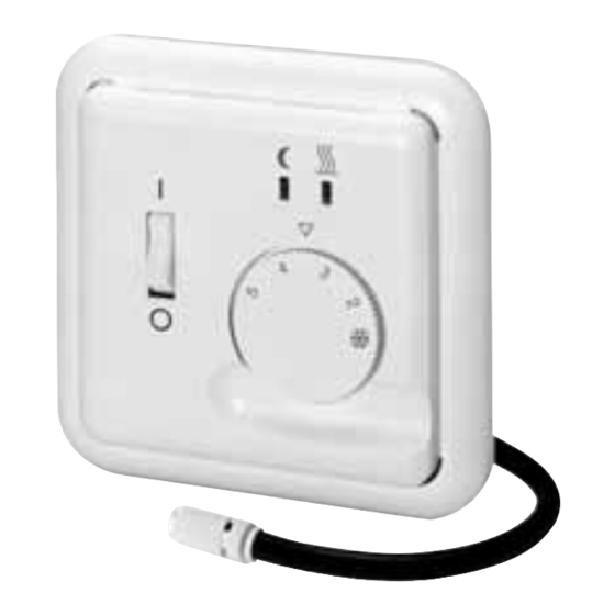
2.1. Steuergerät:
Mit dem Einstellknopf stellen Sie die von Ihnen gewünschte Temperatur ein, die Ihr Fuß-
boden haben soll. Die Zahlenskala
❄
- 5 auf dem Knopf entspricht einem Temperatur-
bereich von 10 - 50 °C bzw. 10- 40 °C. Beachten Sie bitte hierzu die Einstellvorschriften
des Herstellers Ihrer Fußbodenheizung. Wird die von Ihnen eingestellte Temperatur im
Fußboden unterschritten, fordert das Steuergerät Wärme an und dieser Zustand wird
durch die rote LED über dem Einstellknopf angezeigt. Sie sehen also, wenn Ihre Heizung
Energie verbraucht. Im Einstellknopf kann auch eine Bereichseinengung vorgenommen
werden, nähere Beschreibung siehe unter Punkt 8. Mit dem Netzschalter 0 - I wird der
Betriebszustand Ihrer Fußbodenheizung ein- oder ausgeschaltet. Sie haben auch die
Möglichkeit, über eine externe Schaltuhr eine Temperaturabsenkung z.B. für die
Nachtstunden zu programmieren. Sollte eine solche Schaltuhr bei Ihnen installiert sein,
so wird der Zeitpunkt des Beginns der Temperaturabsenkung durch die grüne LED über
dem Einstellknopf angezeigt. Die Temperaturabsenkung beträgt ca. 5 °C.
Beispiel: Die von Ihnen am Steuergerät eingestellte Temperatur beträgt 40°C
(= Zahlenskala 4). Das bedeutet, daß die Temperatur im Fußboden z. B. in den Nacht-
stunden bis auf 35°C absinken kann, ohne daß sich Ihre Heizung einschaltet. Erst nach
einem weiteren Absinken der Temperatur würde sich Ihre Heizung wieder einschalten.
2.2. Fühler
Der Fühler ist im Fußboden installiert. Er überwacht die von Ihnen am Steuergerät ein-
gestellte Fußbodentemperatur und gibt den Befehl zum Ein- und Ausschalten der
Fußbodenheizung.
3. Montage
3.1. Steuergerät:
auf handelsübliche Unterputzdose Ø 55.
ACHTUNG! Das Gerät ist mit seinem Tragring immer auf der Tapete zu montieren!
a) Gehäusedeckel entfernen. Einstellknopf abziehen. Deckelschraube lösen. Deckel
abziehen.
b) Elektrischer Anschluß:
Gemäß Schaltbild; Massivleiter – Querschnitt 1 bis 2,5 mm
2
. Kein Schutzleiter erfor-
derlich. Schutzleiterklemme dient nur zum Durchschleifen. Durch entsprechende
Einbaumaßnahmen kann Schutzklasse II erreicht werden.
c) Regler mittels gewindeformender UP-Dosen-Schraube auf Dose montieren.
d) Gehäusedeckel aufsetzen. Dazu Deckel links oben in das Gehäuseunterteil einrasten.
e) Weiter wie bei a), jedoch in umgekehrter Reihenfolge.
3.2. Fühler:
– Der Fühler muß unbedingt in einem Schutzrohr verlegt werden. Dadurch ist er vor
Feuchtigkeit geschützt und kann bei einem evtl. Reparaturfall leicht ausgewechselt
werden.
– Die mitgelieferten Adernendhülsen DIN 46228-D 1-7-Ms müssen auf
der notwendigen abisolierten Leitungslänge s. Skizze montiert werden.
4. Hinweise für den Installateur
– Der Schalter 0 - I auf dem Steuergerät trennt das Gerät einpolig vom Netz und unter-
bricht den Stromkreis zum Heizwiderstand im Fußboden.
– Bei Arbeiten am Lastkreis ist grundsätzlich die Netzspannung abzuschalten, z.B.
Sicherung entfernen
– Bei Fühlerunterbrechung ist der Relaiskontakt geschlossen, bei Fühlerkurzschluß ist
der Relaiskontakt offen.
– Achtung! Im Fehlerfall kann Netzpotential am Fühler anliegen
5. Technische Daten
5.1. Steuergerät:
Bestellbezeichnung
Farbe reinweiß, RAL 9010
FRe 525 22 rw
EDV-Nr. (incl. Fühler)
0525 22 141 500
Bestellbezeichnung
Farbe elektroweiß, RAL 1013
FRe 525 22
EDV-Nr. (incl. Fühler)
0525 22 141 501
Betriebsspannung
AC 230 V 50 Hz
Toleranzbereich
AC 195....253 V 50 Hz
❄
Temperatureinstellbereich (Zahlenskala)
....5 (= 10 . . . 50° C)
für Varianten 0525 22 141 56...
❄
....5 (= 10 . . . 40°C)
10 A bei cos ϕ=1
Schaltstrom bei AC 250 V
Schaltleistung
2,3 kW
Schalter
Netz „Ein/Aus"
Anzeige LED rot
Steuergerät fordert Wärme an
(Heizbetrieb)
Anzeige LED grün
Temperaturabsenkung „Ein"
Kontakt (Relais)
1 Schließer (für Heizen),
(nicht potentialfrei)
Temperaturabsenkung (TA)
ca. 5 K
Schalttemperaturdifferenz
ca. 1 K
Schutzart Gehäuse nach DIN VDE 0470 T 1
IP 30
Betriebstemperatur
T 40
Lagertemperatur
-25 T 70
5.2. Fernfühler weiß
Bestellbezeichnung
F 193 720 A
EDV-Nr.
000 193 720 001
Fühlelement
NTC
Fühlerkabel
PVC, 2 x 0,50 mm
, 4 m
2
Schutzart nach DIN VDE 0470 T 1
IP 68
Umgebungstemperatur
-25 T 70
Das Fühlerkabel kann bei Bedarf mit einer 2-adrigen Leitung mit einem Querschnitt von
1,5 mm
2
bis auf 50 m verlängert werden, ohne die Genauigkeit des Reglers zu beein-
flussen. Bei Verlegung in Kabelkanälen oder in der Nähe von Starkstromleitungen soll-
te eine abgeschirmte Leitung verwendet werden.
Fühlerkennwerte:
Meßgerät Ri > 1 M Ω
Temperatur °C . . . . . . . . .Widerstand k Ω
Temperatur °C . . . . . . .Widerstand k Ω
5 . . . . . . . . . . . . . . . . . . . .85,279
30 . . . . . . . . . . . . . . . . . .26,281
10 . . . . . . . . . . . . . . . . . . . .66,785
35 . . . . . . . . . . . . . . . . . .21,137
15 . . . . . . . . . . . . . . . . . . . .52,330
40 . . . . . . . . . . . . . . . . . .17,085
20 . . . . . . . . . . . . . . . . . . . .41,272
45 . . . . . . . . . . . . . . . . . .13,846
25 . . . . . . . . . . . . . . . . . . . .33,000
50 . . . . . . . . . . . . . . . . . .11,277
Die Widerstandswerte können nur bei abgeklemmtem Fühler gemessen werden.
6. Schaltbild
7. Maßbild
Regler / Fernfühler
20
8. Einengung des Temperatur-Einstellbereiches
❄
Werkseitig ist der Regler auf den maximalen Einstellbereich von
bis 5 eingestellt.
Im Einstellknopf befinden sich 2 Einstellringe, allerdings mit einem Einstellbereich von 5
bis 30°C. Bei der Bereichseinengung bitten wir die Einstellung gemäß nachfolgendem
Diagramm vorzunehmen.
Irrtum und Änderungen vorbehalten
Operating instructions for
UP-Floor Heating Controller
FRe 525 22
IMPORTANT NOTE!
This unit must be mounted by an expert, according to the wiring diagram inside the
housing cover. The existing safety re-gulations must be observed.
Ö
Will be met by corresponding installation (acc. to VDE 0100) and by fitting on
smooth and non-conductive and non-flammable surface.
This electronic room thermostat which can be mounted independently is for control-
ling normal ambient temperature in dry, enclosed rooms only. It has radio interference
suppression in accordance with VDE 0875 or EN 55014 and operates to efficiency 1 C.
1. Application:
In building installation practice for the regulation of thermal storage floor heating
systems with heating mats.
2. Functional description:
The floor heating controller consists of two parts:
2.1. Control device for setting the required floor heating temperature.
2.2. Remote sensor in the floor for monitoring the set temperature.
2.1. Control device:
The required floor temperature can be set with the control knob. The number scale
the knob corresponds to a temperature range of 10 - 50 °C (resp. 10 - 40 °C). Please
note the setting instructions of the manufacturer of your floor heating. If the set floor hea-
ting temperature is not reached, heat is requested by the control device and this state is
indicated by the red LED located above the control knob; this shows when your heating
is using energy. The control knob can also be used to limit the temperature adjustment
range; detailed description in Item 8. The floor heating can be switched on and off with
the O/I mains switch. A temperatue reduction can also be programmed via an external
timer, e.g. for off-peak operation at night. If your system is provided with a timer, the start
of the temperatue reduction is indicated by the green LED located above the control
knob. The temperature reduction is about 5°C.
Example: The set day temperature is 30°C. This means that the floor temperature can
fall to 25°C, e.g. for off-peak operation at night without the heating be switched on. The
heating only switches on if the temperature falls further.
2.2. Sensor
The sensor is installed in the floor. It monitors the floor temperature set at the control
device and gives the command to switch the floor heating system on and off.
3. Installation
3.1. Control device:
On standard flush-type box 55 diameter.
NOTE! The device must always be mounted with ists supporting ring on the wall
covering!
a) Remove housing cover – Pull off control knob – Loosen cover screw – Remove
cover
b) Electrical connection:
According to circuit diagram; solid conductor – 1 to 2.5 mm
protective conductor is necessary. The protective conductor terminal only serves for
looping-in. The class of protection II can be achieved by means of appropriate instal-
lation measures.
c) Mount controller on box by means of thread-forming flush-type box screw.
d) Fit housing cover. Fit cover so that it snaps into place on the left at the bottom of the hou-
sing.
e) Proceed as under a), however in reverse order.
3.2. Sensor:
– The sensor must be installed in a protective tube, so that it is protecred from moisture
and easy to replace in case of repair.
– Attached cable end sleeves DIN 46228-D 1-7-Ms have to be
mounted to the de-insulated part on conductor (see sketch).
4. Information for the installer
– The O/I switch on the control device disconnects the device in one pole from the mains
supply and interrupts the circuit to the heating resistor in the floor.
– When working on the load circuit, the system voltage must be disconnected (e.g.
remove fuse).
– With sensor open-circuit, the relay contact is closed; with sensor short-circuit, the
relay contact is open.
– ATTENTION! In case of failure mains supply might be on sensor cable.
5. Technical data
5.1. Control device:
Ordering designation
colour pure white, RAL 9010
FRe 525 22 rw
EDP-number (incl. sensor)
0525 22 141 500
Ordering designation
colour electrowhite, RAL 1013
FRe 525 22
EDP number (incl. sensor)
0525 22 141 501
Operating voltage
230 V AC, 50 Hz
Tolerance range
195....253 V AC, 50 Hz
Temperatur adjustment range Number scale
❄
for variants 0525 22 141 56...
❄
10 A at cos ϕ=1
Switching current
Switching capacity
2,3 kW
Switch
Mains „On/Off"
Red LED display
Control device request heat
(heating operation)
Green LED display
Temperature reduction „On"
22435/1
Contact (relay)
Temperature reduction (TA)
Switching temperature difference
Degree of protection of housing according
to DIN VDE 0470 T 1
Operating temperature of control device
Storage temperature
5.2. Remote sensor white
Order designation
EDP number
Sensing element
Sensor cable
Degree of protection according to
DIN VDE 0470 T 1
Ambient temperature
The sensor cable can be extendet up to 50 m with a two-core cable with a crossection of
1.5 mm
2
without influencing the accuracy of the controller.
Sensor characteristics:
Measuring instrument Ri > 1 M Ω
Temperature °C . . . . . . . .Resistance k Ω
5 . . . . . . . . . . . . . . . . . . . .85,279
10 . . . . . . . . . . . . . . . . . . . .66,785
15 . . . . . . . . . . . . . . . . . . . .52,330
20 . . . . . . . . . . . . . . . . . . . .41,272
25 . . . . . . . . . . . . . . . . . . . .33,000
The resistance values can only be measured with the sensor disconnected.
6. Block diagram
❄
-5 on
7. Dimension drawing
Controller/remote sensor
2
rated cross-section. No
Detail Z
Disconnection of wire
8. Limitation of temperature adjustment range
The controller is set at the works to the maximum adjustment range from
The control knob has two setting rings, however with one adjustment range from 5 to
30°C. For range limitation, adjustment should take place as illustrated in the diagramm
below.
Limitation of range
with control button
....5 (= 10 . . . 50 ° C)
....5 (= 10 . . . 40 °C)
Controller adjusment range
Sensor temperature in °C
1 NO contact (for heating)
(not floating)
About 5 K
About 1 K
IP 30
T 40
-25 T 70
F 193 720 A
000 193 720 001
NTC
PVC, 2 x 0,50 mm
, 4 m
2
IP 68
-25 T 70
Temperature °C . . . . . .Resistance k Ω
30 . . . . . . . . . . . . . . . . . .26,281
35 . . . . . . . . . . . . . . . . . .21,137
40 . . . . . . . . . . . . . . . . . .17,085
45 . . . . . . . . . . . . . . . . . .13,846
50 . . . . . . . . . . . . . . . . . .11,277
for socket acc. to
DIN 49073
20
❄
to 5.
Errors possible – subject to alterations
22435/2

Verwandte Anleitungen für Eberle FRe 525 22


Inhaltszusammenfassung für Eberle FRe 525 22
- Seite 1 – Bei Fühlerunterbrechung ist der Relaiskontakt geschlossen, bei Fühlerkurzschluß ist Ordering designation below. Diagramm vorzunehmen. der Relaiskontakt offen. colour pure white, RAL 9010 FRe 525 22 rw – Achtung! Im Fehlerfall kann Netzpotential am Fühler anliegen EDP-number (incl. sensor) 0525 22 141 500 Limitation of range with control button Ordering designation 5.
- Seite 2 Elément sensible Câble PVC, 2 x 0,50 mm , 4 m Type FRe 525 22 Protection selon DIN VDE 0470 T 1 IP 68 Température d’ambiance -25 T 70 En cas de nécessité, il est possible de prolonger le câble de sonde jusqu’à 50 m avec un câble une paire de 1,5 mm...