Harvia SIGMA CS110 Gebrauchsanleitung
Inhaltsverzeichnis
Quicklinks
HARVIA SIGMA CS110
Ohjauskeskus
Styrenhet
Control unit
Steuergerät
Пульт управления
Juhtimiskeskus
Centre de contrôle
Sterownik
Vadības pults
Valdymo pultas
Адрес:
Centralina di controllo
ООО «Харвия РУС».
196084, г. Санкт-Петербург,
ул. Заставская, дом 7
E-mail: regionlog12@mail.ru
29022016/ZVR-911
Inhaltsverzeichnis

Verwandte Anleitungen für Harvia SIGMA CS110


Inhaltszusammenfassung für Harvia SIGMA CS110
- Seite 1 HARVIA SIGMA CS110 Ohjauskeskus Styrenhet Control unit Steuergerät Пульт управления Juhtimiskeskus Centre de contrôle Sterownik Vadības pults Valdymo pultas Адрес: Centralina di controllo ООО «Харвия РУС». 196084, г. Санкт-Петербург, ул. Заставская, дом 7 E-mail: regionlog12@mail.ru 29022016/ZVR-911...
-
Seite 2: Inhaltsverzeichnis
Ofens bzw. des Steuergeräts oder der für die War- tung der Anlagen zuständigen Person auszuhändi- CONTROL UNIT HARVIA SIGMA (CS110) gen. Control unit's purpose of use: the control unit is meant for controlling the functions of a sauna STEUERGERÄT HARVIA SIGMA (CS110) -
Seite 3: Harvia Sigma
1. HARVIA SIGMA 1.1. General 1.1. Allgemeines The purpose of Harvia Sigma control unit is to con- Der Zweck des Steuergeräts Harvia Sigma ist es, ei- trol an electric sauna heater within an output range nen elektrischen Saunaofen innerhalb einer Ausgangs- of 2.3–17 kW. -
Seite 4: Troubleshooting
1.3. Troubleshooting 1.3. Störungsbeseitigung If an error occurs, the heater power will cut off and Wenn eine Störung auftritt, wird der Ofen abge- the control panel will show an error message ”E schaltet, und auf dem Bedienfeld wird eine Fehler- (number)”, which helps troubleshooting the cause meldung im Format “E (Nummer)”... -
Seite 5: Heater Off
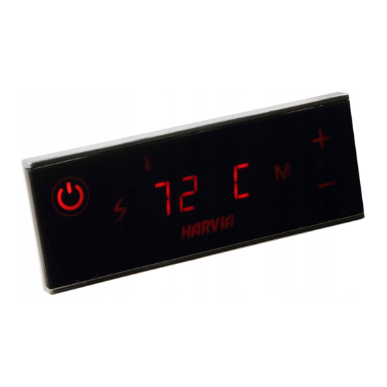
turn the heating elements on and off in periods. Temperatur beizubehalten, schaltet das Steuerge- If the heater efficiency is suitable and the sauna rät die Heizelemente in regelmäßigen Zeitabstän- has been built correctly, the sauna takes no more den ein und aus. than an hour to warm up. - Seite 6 Einstellungen Settings Drücken Sie die Taste 4. Press button 4. Temperatur. Der Einstellbereich beträgt Temperature. The adjustment range is 80 C 80 C 40–110 °C. 40–110 °C. Drücken Sie die Taste 4. Press button 4. Verbleibende Einschaltzeit. Der Mindest- Remaining on-time. The minimum value 4:00 4:00 wert beträgt 10 Minuten.
- Seite 7 Sensor reading adjustment. The reading Einstellung des Fühlerwerts. Die can be corrected by +/-10 units. The Messwerte können um +/- 10 Einheiten adjustment does not affect the measured korrigiert werden. Die Einstellung betrifft temperature value directly, but changes nicht den gemessenen Temperaturwert the measuring curve.
-
Seite 8: Instructions For Installation
3. INSTRUCTIONS FOR INSTALLATION 3. INSTALLATIONSANLEITUNG The electrical connections of the control unit Die elektrischen Anschlüsse des Steuergeräts dür- may only be made by an authorised, professional fen nur von einem autorisierten, geschulten Elektri- electrician and in accordance with the current ker unter Beachtung der aktuell gültigen Vorschrif- regulations. -
Seite 9: Installing The Power Unit
3.2. Installing the Power Unit 3.2. Montage der Leistungseinheit Install the power unit to a wall outside the sauna Bringen Sie die Leistungseinheit an einem trocke- room, in a dry place with an ambient temperature nen Ort außerhalb der Saunakabine mit einer Um- of >0 ºC. - Seite 10 Control of electric heating Steuerung der elektrischen Heizung Temperature sensor (3=red, 4=yellow) Temperaturfühler (3=rot, 4=gelb) Overheat protector (1=blue, 2=white) Überhitzungsschutz (1=blau, 2=weiß) Control panel Bedienfeld POWER SUPPLY 5 x 2,5 mm² 5 x 2,5 mm² HAUPTZENTRALE 3 x 1,5 mm² 3 x 1,5 mm²...
-
Seite 11: Installing The Temperature Sensor
3.3. Installing the Temperature Sensor 3.3. Montage des Temperaturfühlers Note! Do not install the temperature sensor closer Achtung! Der Temperaturfühler darf nicht näher als than 1000 mm to an omnidirectional air vent or 1000 mm an einen Mehrrichtungs-Luftschlitz oder closer than 500 mm to an air vent directed away näher als 500 mm an einen Luftschlitz angebracht from the sensor. - Seite 12 min. 100 mm max. 200 mm WX232 WX232 WX232 A min. A max. A min. A min. A max. A min. WX232 Tempera- ture sensor Temperatur- Heater A min. A max. D min. fühler Ofen BC105 1250 F10,5 1400 K11G 1200 1250 1250...
-
Seite 13: Resetting The Overheat Protector
3.4. Resetting the Overheat Protector 3.4. Zurückstellen der Überhitzungsschutzes The sensor box (WX232) contains a temperature Das Fühlergehäuse (WX232) enthält einen Tempe- sensor and an overheat protector. If the tempera- raturfühler und einen Überhitzungsschutz. Wenn ture in the sensor’s environment rises too high, the die Temperatur in der Umgebung des Temperatur- overheat protector cuts off the heater power.