Electro-Voice P3000RL Bedienungsanleitung
Verfügbare Sprachen
Verfügbare Sprachen
Quicklinks
Kapitel

Verwandte Anleitungen für Electro-Voice P3000RL


Inhaltszusammenfassung für Electro-Voice P3000RL
- Seite 1 OWNER‘S MANUAL BEDIENUNGSANLEITUNG...
- Seite 17 BEDIENUNGSANLEITUNG...
- Seite 18 INHALT WICHTIGE SICHERHEITSHINWEISE ....... WICHTIGE SERVICEHINWEISE ....... BESCHREIBUNG ....... AUSPACKEN & GARANTIE ..........INSTALLATIONSHINWEISE FRONTSEITE ....... RÜCKSEITE ....... INPUT A / INPUT B ....... PARALLEL ....... DSP OUT ..........CONTROL PORT ....... RS-232 INTERFACE ....... ADDRESS REMOTE CAN-BUS .......
-
Seite 19: Wichtige Sicherheitshinweise
WICHTIGE SICHERHEITSHINWEISE Das Blitzsymbol innerhalb eines gleichseitigen Drei- ecks soll den Anwender auf nicht isolierte Leitungen und Kontakte im Geräteinneren hinweisen, an denen hohe Spannungen anliegen, die im Fall einer Berührung zu lebensgefährlichen Stromschlägen führen können. Das Ausrufezeichen innerhalb eines gleichseitigen Dreiecks soll den Anwender auf wichtige Bedienungs- sowie Servicehinweise in der zum Gerät gehör- enden Literatur aufmerksam machen. -
Seite 20: Beschreibung
BESCHREIBUNG Herzlichen Glückwunsch! Sie haben sich mit einer Endstufe der PRECISION SERIES von Electro- Voice für ein Gerät modernster Technologie entschieden. Die Endstufen der P-Serie vereinen überragende Audio-Performance mit höchster Zuverlässigkeit und Betriebssicherheit. Jede Endstufe ist mit dem RCM-24 Remote Control Modul ausgestattet, welches die zentrale Konfiguration, Steuerung und Überwachung aller relevanten Endstufenparameter (wie Ausgangsstrom, -spannung, Lastimpedanz, ...) ermöglicht. -
Seite 21: Auspacken & Garantie
BESCHREIBUNG Neben der Steuerung und Überwachung stellt das RCM-24 Remote Control Modul umfangreiche Si- gnalverarbeitungsfunktionen zur Verfügung. Enthalten sind insgesamt 20 parametrische Filter, X-Over Funktionen, Delays, Routing und Level Control, sowie Kompressor und Limiter pro Kanal. Sämtliche Parameter sind frei editierbar und können auf dem Modul in bis zu 8 User Memories abgespeichert werden. -
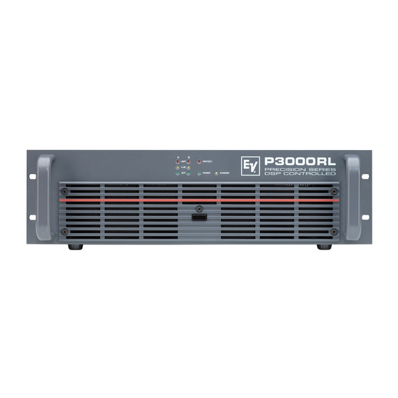
Seite 22: Frontseite
FRONTSEITE Mit dem POWER Schalter in der Mitte der Frontblende wird das Gerät eingeschaltet. Eine Softstart- Schaltung vermeidet dabei Einschaltstromspitzen auf der Netzleitung. Dadurch wird verhindert, dass der Leitungsschutzschalter des Stromnetzes beim Einschalten der Endstufe anspricht. Die Lautspre- cher werden über die Ausgangsrelais um ca. 2 Sekunden verzögert zugeschaltet, wodurch etwaige Einschaltgeräusche effektiv unterdrückt werden. -
Seite 23: Rückseite
RÜCKSEITE INPUT A / INPUT B Die Eingänge INPUT A & INPUT B sind elektronisch symmetrisch mit einer Eingangsempfindlichkeit von +6dBu (1.55V) für den direkten Betrieb mit Mischpul- ten usw. ausgelegt. Der Anschluss kann entweder über die XLR-Ein- gangsbuchsen oder die parallelgeschalteten Schraub- steckverbindungen, die im Lieferumfang enthalten sind, erfolgen. -
Seite 24: Rs-232 Interface
RÜCKSEITE RS-232 INTERFACE Das RS-232 Interface dient als Schnittstelle zu Mediensteuerungssystemen bzw. Gebäudemanagementsystemen. Über RS-232 können sämtliche Para- meter gesteuert und abgefragt werden. Die Kommunikation erfolgt über ein einfach zu implementierendes ASCII Protokoll. Auf diese Weise können die Remote Verstärker problemlos in Medien- und Touchpanel-Steuerungen integriert werden. Program- mierhinweise und eine vollständige Protokollbeschreibung finden Sie in der IRIS Dokumentation. -
Seite 25: Easy Remote
RÜCKSEITE Die LED STATUS dient zur Kontrolle der Kommunikation am CAN-Bus. Wenn die Adresse 00 eingestellt und die Endstufe softwaremässig vom CAN-Bus abgekoppelt ist, blinkt die LED regelmässig alle 3 Sek. kurz auf. Wenn eine Adresse zwischen 01 und 250 eingestellt ist, aber noch keine CAN-Bus Aktivität stattgefun- den hat, blinkt die LED regelmässig jede Sekunde kurz auf. -
Seite 26: Limiter
RÜCKSEITE LIMITER Der eingebaute Limiter zur Vermeidung von Übersteuerungen ist in seiner Zeitkonstante umschaltbar. Normalerweise sollte die Stellung SLOW benutzt werden (Auslieferungszustand). Bei Verwendung der Endstufe als Mittel-Hochtonendstufe in aktiven Mehr- wegsystemen sollte der Limiter in Position FAST betrieben werden. Bei Verwendung der Endstufe als Bassendstufe in aktiven Mehrwegsyste- men sollte der Limiter in Position SLOW betrieben werden. -
Seite 27: Verkabelung
VERKABELUNG NF-VERBINDUNGSKABEL Als NF-Verbindung wählen Sie am besten symmetrisch ausgelegte Kabel (2 Signaladern + Schirmge- flecht) mit XLR-Stecker. Obwohl alle Endstufeneingänge auch unsymmetrisch belegt werden können, stellt ein symmetrisch ausgeführtes NF-Verbindungskabel die bessere Alternative zu einer unsymme- trischen Verbindung dar. Die meisten Audiogeräte verfügen über symmetrisch aufgebaute Ausgänge. Der Schirm im Kabel verbindet bei symmetrischer Signalführung alle metallischen Gehäuse und ver- hindert dadurch lückenlos ein Einkoppeln von externen Störsignalen, im wesentlichen Brummen, auf den Audiosignalpfad. -
Seite 28: Netzwerk-Beispiele
NETZWERK-BEISPIELE Die folgenden Bilder zeigen Beispiele von Datenbusverdrahtungen in unterschiedlichen Grössen- ordnungen: System mit 5 Verstärkern und einem UCC1 / PC am Bus-Anfang Abschluss-Stecker am UCC1 (Bus-Anfang) und am Verstärker 5 (Bus-Ende) System mit 2 Racks und einem UCC1 / PC in der Mitte Abschluss-Stecker an Verstärker 6 (Bus-Anfang) und Verstärker 12 (Bus-Ende) - Seite 29 NETZWERK-BEISPIELE System mit mehreren Racks und mehreren UCC1 / PCs UCC1 an beliebigen Stellen im CAN-Bus Abschluss-Stecker an Verstärker 10 (Bus-Anfang) und Verstärker 16 (Bus-Ende) In der Netzwerk-Verkabelung ist neben dem CAN-Bus auch das symmetrische Audio-Monitor Signal zum Abhören der Endstufeneingänge und -ausgänge mitgeführt. Dieser Monitorbus ermöglicht das softwaregesteuerte Abhören der Eingangs- oder Ausgangssignale aller im Remote-Netzwerk vorhan- denen Endstufen ohne zusätzlichen Verdrahtungsaufwand.
-
Seite 30: Can-Bus
CAN-BUS Der CAN-Bus erlaubt die Verwendung unterschiedlicher Baud Rate Bus Länge Datenraten, wobei die Datenrate indirekt proportional zur 500 kbit/s 100 m Buslänge ist. Wenn das Netzwerk nur eine geringe Ausdeh- 250 kbit/s 250 m nung hat, sind höhere Baudraten bis zu 500 kbit/s möglich. Bei grösseren Ausdehnungen muss die Baudrate herabge- 125 kbit/s 500 m... -
Seite 31: Netzbetrieb & Wärmeentwicklung
Massnahmen abgeleitet werden. Zur Berechnung der Wärmeverhältnisse im Rack/Schrank bzw. nötiger Abluftmassnahmen kann die nachfolgende Tabelle benutzt werden. Die Spalte P zeigt die Verlustleistung bei verschiedenen Betriebszuständen. Die Spalte BTU/hr zeigt die abgegebene Wärmemenge je Stunde. P3000RL Normal Mode BTU/hr Netz Netz Netz... -
Seite 34: Block Diagram Amplifier
BLOCK DIAGRAM AMPLIFIER... -
Seite 35: Block Diagram Rcm-24
BLOCK DIAGRAM RCM-24... -
Seite 36: Dimensions / Abmessungen
DIMENSIONS / ABMESSUNGEN 375,5 132,5... - Seite 37 NOTES...
- Seite 38 NOTES...
- Seite 39 NOTES...