Inhaltsverzeichnis
Werbung
Verfügbare Sprachen
Verfügbare Sprachen
Quicklinks
Werbung
Inhaltsverzeichnis
Fehlerbehebung

Verwandte Anleitungen für Electro-Voice N8000


Inhaltszusammenfassung für Electro-Voice N8000
- Seite 1 OWNER’S MANUAL BEDIENUNGSANLEITUNG...
-
Seite 2: Inhaltsverzeichnis
Configuration ..............28 Configuration and testing of an Ethernet connection with N8000......28 Appendix . - Seite 3 Konfiguration ..............69 Aufbau und Überprüfung einer Ethernet-Verbindung mit dem N8000 ..... 69 Anhang .
- Seite 4 Any work security regulations that are applicable at the locations where the appliance is being serviced have to be strictly obeyed. This applies also to any regulations about the work place itself. All instructions concerning the handling of MOS-circuits have to be observed. NOTE: SAFETY COMPONENT (MUST BE REPLACED BY ORIGINAL PART) NetMax N8000 System Controller Owner’s manual...
- Seite 5 Emissions from Low Voltage Electrical Equipment in the Range of 9 kHz to 40 GHz. Limit: DIN EN 55022:1999-05 Information Technology Equipment Radio Disturbance Characteristics – Limits and Methods of Measurement Verified by: Date: Straubing, May 2 , 2006 NetMax N8000 System Controller Owner’s manual...
-
Seite 6: Introduction
PC Software IRIS-Net - Intelligent Remote & Integrated Supervision. The central unit of NetMax is the N8000 system controller with up to 32 audio channels, mixer and matrix functions, signal processing and extensive control and monitoring functions. Several N8000 can be connected via a CobraNet™... -
Seite 7: N8000 Features
IRIS-Net. With that, you choose the desired components from a signal processing library, place them in a working area on the screen and wire them to a signal flow chart. Thus, the resulting DSP configuration has only to be transferred to the N8000 and is ready for immediately use. -
Seite 8: Unpacking And Warranty
(GPOs). A PC can be connected to the USB port on the front faceplate if the N8000 has been installed in a rack and the Ethernet port cannot be reached easily. Via the USB interface the network parameters of the N8000 can be edited and files containing the entire N8000 configuration can be transferred. -
Seite 9: Installation Instruction
Devices with an opposing routing of air flow should not be installed in the same rack. When installing the N8000 in a rack, a free air duct between the sides of the N8000 and the side panel of the rack to the upper rack ventilation must be observed in order to ensure sufficient air ventilation. -
Seite 10: Browser Interface
Introduction 1.6 Browser Interface Some of the configuration and operation options of the N8000 which are available in IRIS-Net are also provided by the N8000 browser interface. Any standard Internet browser with activated JavaScript and CSS can be utilized in order to use the browser interface. Please find the detailed information on the N8000 browser interface in the file N8000 browser manual in the IRIS-Net setup directory (\Documentation\NetMax). -
Seite 11: Control Elements And Connections
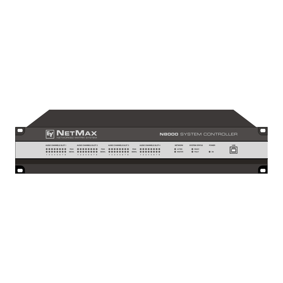
2 Control Elements and Connections 2.1 Front Faceplate The front faceplate of the N8000 has level and status displays and it offers also the possibility to connect a PC via a USB interface. SIGNAL / PEAK-LEDs exist for all 32 audio channels. The channels are combined to groups of 8 and assigned to the audio-slots 1 to 4 at the rear. -
Seite 12: System Status-Leds
Control Elements and Connections clock master breaks down or is removed from the network, another N8000 will take over this function automatically. SYSTEM STATUS-LEDs These LEDs indicate device or system states. The READY- LED is on when the device has booted after switch-on and when it is ready for operation. -
Seite 13: Rear Panel
N8000 detects the type of the module automatically and offers the corresponding configuration possibilities. ATTENTION: The N8000 has to be switched off if you want to change or install a module. You will find detailed instructions in the data sheet of the corresponding module. Network Module Slot This slot is provided for the installation of a network module, e.g. -
Seite 14: Ethernet Interface
N8000 automatically detects an installed network module. The module can be configured in the PC software IRIS-Net. ATTENTION: The N8000 has to be switched off if you want to change or install a module. You will find detailed instructions in the data sheet of the corresponding module. ETHERNET Interface... -
Seite 15: Control Port
The N8000 can be switched on and off with the power switch on the rear of the device. The ON- LED on the front panel is immediately illuminated after switch-on. The N8000 boots and initializes all parameters with those values that had been previously active. -
Seite 16: Preparations
2. Connect the power cable. Please pay attention that the power switch of the N8000 (above the mains connector) is off. 3. Install the program IRIS-Net (Intelligent Remote & Integrated Supervision) on your PC. -
Seite 17: System Expansion With Analog/Digital Inputs Or Outputs
1 DSP expansion module (DSP-1) for the expansion of the storage capacity and signal pro- cessing ATTENTION: It is essential to switch off the N8000 if you want to install or change a module. You will find detailed instructions in the data sheet of the corresponding module. System expansion with analog/digital inputs or outputs There are four slots at the rear of the N8000 which are intended to expand the systems with analogue or digital inputs or outputs. -
Seite 18: Interface Description
Amplifiers) can be operated and monitored. By using appropriate network hardware it is even possible to operate the N8000 via a wireless network (WLAN). The Ethernet interface on the rear of N8000 is a RJ-45 connector (8P8C). Both 10Base-T and 100Base-TX Ethernet standards are supported. -
Seite 19: Can Interface
10Base-T as well. If the N8000 is connected via a patch cable to a hub/switch, the wiring of the cable at pin 1 of the first connector has to be connected with Pin 1 of the other connector; this is the same regarding the other pins as well. - Seite 20 Please see the CAN bus principles chapter on page 37 in the appendix of this document as well as the instruction manuals of the connected devices for further information on CAN bus (especially on system examples and performance specifications). NetMax N8000 System Controller Owner’s manual...
-
Seite 21: Usb Connection
Accordingly, the low speed (1,5 MBit/s) and full speed (12 MBit/s) transfer rates are supported. According to USB specifications, the cable which is connected to this interface must not be longer than 5 meters. The USB interface of the N8000 is a USB-B (female) connector. -
Seite 22: Control Port
Preparations The pins of the RS-232 interface used in the N8000 are indicated in the following illustration and table. Connections which are not given are internally connected in the N8000 so that the communication between the N8000 and the connected device is possible via a software handshake system. - Seite 23 N8000. A voltage which can be changed via a potentiometer is connected at the control input 1. The N8000 can be configured via IRIS-Net so that this voltage can be used to adjust a variable parameter, for example, adjusting the volume of an audio input or output.
-
Seite 24: Audio Interfaces
The two left connections of the RELAY OUTPUTS are the READY/FAULT output of the N8000. This floating output is closed when the N8000 is ready for operation and no error has occurred. It is possible in IRIS-Net to configure which kind of error causes the contact to be opened. Due to this feature, this contact is especially suitable for the integration of the N8000 in life safety systems (closed current principle). - Seite 25 Digital audio connecting cable It is advisable to choose balanced cables (2 signal conductors + shield) with XLR connectors as digital audio connections. Although all N8000 digital audio inputs can be used unbalanced, balanced audio cable is the better choice.
-
Seite 26: Network Configuration
ID 192.168.1 can be retained and • no other devices have the Host-ID 100. If at least one of these three conditions is not fulfilled, the preset IP address of the N8000 has to be changed. Example: The following illustration shows an example application with four NetMax N8000 in a closed network. - Seite 27 The assignment of the IP address can be made via IRIS-Net and via the N8000 browser interface. In IRIS-Net the assignment is possible both over the USB interface and the Ethernet interface of the N8000. Information about the exact proceedings are given in the IRIS-Net online-help.
-
Seite 28: Configuration
Configuration and testing of an Ethernet connection with N8000 The purpose of this procedure is to build a connection between a PC and a N8000 with factory network settings (see page 26) via Ethernet and to check the proper function of this connection. - Seite 29 The pop-up window Internet Protocol (TCP/IP) Properties appears. 5. Choose the option Use the following IP address in the window. 6. Type 192.168.1.1 in the IP address input field. 7. Type 255.255.255.0 in the Subnet mask input field. NetMax N8000 System Controller Owner’s manual...
- Seite 30 10. Connect the N8000 to the power supply system and switch it on by operating the power switch on the rear. The green ON-LED (see page 12) on the front panel of the N8000 is illuminated. After some seconds the green READY-LED (see page 12) is also illuminated and signals the successful start activity of the N8000.
-
Seite 31: Network Configuration
12. Enter ping 192.168.1.100 and tap the return button. The PC is now checking the connection with the N8000. For this four network packets are sent to the N8000 via Ethernet then the N8000 has to confirm these packets. If the Ethernet connection is successful, no packets get lost. -
Seite 32: Appendix
PC where the IRIS-Net (Intelligent Remote & Integrated Supervision) software is used to operate the N8000 and the remote amplifiers. It is not only possible to operate and control the system via IRIS-Net, but also to monitor the whole system. The N8000 and the PC are connected via Ethernet. -
Seite 33: Troubleshootings
Appendix 5.2 Troubleshootings Problem: It is not possible to establish a connection with the N8000 via IRIS-Net. Host not reachable (Timeout) N8000 activated? Switch on N8000 IP address in unknown IRIS correct? N8000 Find out IP online? address Correct IP... -
Seite 34: Ethernet Principles
IP addresses are allocated manually. Switch off the N8000 and try to ping the IP address of the off-state N8000 via a command line prompt (see page 31 of this manual). If the ping is successful, another device has the address of the off-state N8000. In this case, change the IP address of the device which is now answering or of the N8000 with the duplicate address (then you also have to change the IP address of the N8000 in IRIS-Net). -
Seite 35: Ip Addresses
Diverse network protocols can be used for the communication of the devices connected to the Ethernet network. The N8000 uses the TCP/IP protocol, thus, it is an IP network device. IP addresses are used for the logical addressing of devices in an IP network. The N8000 uses version IPv4 (Internet protocol version 4) for the addressing. -
Seite 36: Automatic/Manual Allocation Of Ip Addresses
If DHCP is used, certain incidents (e.g. the reboot of a device) can result in the change of the IP address of this device. If this device is a N8000 system controller, its configuration in IRIS-Net has to be modified to reflect the changed IP address. For that reason it is not advisable to use DHCP for the dynamic configuration of N8000. -
Seite 37: Can-Bus Principles
In general, it does not matter if the bus member is a power amplifier, a N8000 or a UCC1 USB-CAN converter. Thus, the N8000 can be connected at any place of the CAN bus. In total, up to 100 devices can be connected to one CAN bus. - Seite 38 In the following figure a star topology from three independent CAN bus systems is given as example. The three CAN buses are connected via two repeaters. NetMax N8000 System Controller Owner’s manual...
-
Seite 39: System Examples
System with 5 power amps and 1 N8000 at the beginning of the bus. Termina- tion plugs at the N8000 (first unit on the bus) and at amp 5 (last unit on the bus). System with 2 amp-racks and 1 N8000/PC in the middle. Termination plugs at power amp 6 (first unit on the bus) and power amp 12 (last unit on the bus). -
Seite 40: Performance Specifications
100 Ω (AWG 24 / AWG 26) can be used for the cabling inside of a rack mounted system. • The previously outlined guidelines for network cabling are mandatory as far as the rack mounted shelve interconnection or fixed installations are involved. NetMax N8000 System Controller Owner’s manual... -
Seite 41: Ip Address Table
Appendix 5.5 IP Address Table Project: _________________________________ Subnet mask Gateway Device IRIS-Net Device Name Location / Description IP Address NetMax N8000 System Controller Owner’s manual... - Seite 42 Appendix NetMax N8000 System Controller Owner’s manual...
- Seite 43 BEDIENUNGSANLEITUNG...
- Seite 44 Konfiguration ..............69 Aufbau und Überprüfung einer Ethernet-Verbindung mit dem N8000 ..... 69 Anhang .
- Seite 45 Eigenmächtige Schaltungsänderungen dürfen nicht vorgenommen werden. Die am Reparaturort gültigen Schutzbestimmungen der Berufsgenossenschaften sind einzuhalten. Hierzu gehört auch die Beschaffenheit des Arbeitsplatzes. Die Vorschriften im Umgang mit MOS-Bauteilen sind zu beachten. NOTE: SAFETY COMPONENT (MUST BE REPLACED BY ORIGINAL PART) NetMax N8000 System Controller Bedienungsanleitung...
-
Seite 46: Einleitung
Bedienung und Überwachung eines NetMax Systems erfolgt durch die PC-Software IRIS-Net – Intelligent Remote & Integrated Supervision. Die Zentraleinheit von NetMax ist der N8000 System Controller mit bis zu 32 Audiokanälen, Mixer- und Matrixfunktionen, Signal Processing und umfangreichen Steuerungs- und Überwachungsfunktionen. -
Seite 47: N8000 Eigenschaften
Charakteristik für die PA-Lautsprecher, Monitor-Lautsprecher, Front Fill Systeme, sowie für die Beschallung von Nebenräumen, Lobby, Angestellten-Bereichen usw. völlig individuell eingestellt und optimiert werden. Anders gesagt, der N8000 meistert jede Anwendung, auch große und komplexe Systeme, absolut exakt und zuverlässig. Neben den reinen Audio-Funktionen ist der NetMax N8000 mit vielfältigen Kontroll-Funktionen ausgestattet. -
Seite 48: Auspacken Und Garantie
Analogfunktionen programmieren. An den Steuerausgängen (GPO’s) können externe Elemente angeschlossen werden, die etwa zur Signalisierung bestimmter Zustände verwendet werden können. Der USB Port an der Frontblende des N8000 dient zum Anschluss eines PCs auch im eingebauten Zustand, d.h. wenn der Ethernet-Port womöglich nur schlecht erreichbar ist. Der USB Port kann zur Übertragung einer Datei mit der gesamten N8000-Konfiguration vom N8000... -
Seite 49: Einleitung
Kaufbeleg und ebenso die Verpackung für eventuelle Rücksendung gut auf. 1.4 Installationshinweise Generell ist der N8000 so aufzustellen oder zu montieren, dass die Luftzufuhr und die Entlüftung an beiden Geräteseiten nicht behindert werden. Die Belüftungsrichtung ist von links nach rechts, wenn man das Gerät von der Frontseite betrachtet. -
Seite 50: Browser Interface
Einleitung Konfiguration auf diesen übertragen werden. Neben der Erstellung von Konfigurationen kann IRIS-Net auch für die umfassende Kontrolle und Überwachung von N8000 System Controllern (und daran angeschlossenen Electro-Voice Precision Series Remote Amplifier) genutzt werden. Hinweise für die Installation von IRIS-Net auf Ihrem PC finden Sie in der Datei „iris_readme.htm“. -
Seite 51: Bedienelemente Und Anschlüsse
Eingangs dauernd oder sehr häufig leuchtet, sollten Sie das entsprechende Eingangssignal etwas zurücknehmen. Falls die PEAK-LED eines Ausgangs dauernd aufleuchtet, sollte die interne Verstärkung reduziert werden, da sonst der N8000 permanent übersteuert wird. NETWORK-LEDs Wenn der N8000 an einem Audio-Netzwerk, z. B. -
Seite 52: System Status-Leds
Ist die LED aus, findet keine Kommunikation über das Audio-Netzwerk statt. Die MASTER-LED leuchtet, wenn der N8000 als Clock-Master – bei CobraNet™ auch als Conductor bezeichnet – fungiert. In einem Audio-Netzwerk gibt es immer nur einen Master, das heißt, die MASTER-LED muss und darf nur an einem N8000 innerhalb des Netzwerk-Verbunds leuchten. -
Seite 53: Rückseite
5V/200mA CAN BUS AUDIO SLOT 4 AUDIO SLOT 2 Auf der Rückseite des N8000 befinden sich sämtliche Anschlüsse für analoge und digitale Audiosignale, Steuer-Schnittstellen und für die Stromversorgung. AUDIO SLOTs Die AUDIO SLOTS 1 – 4 sind Modul-Steckplätze zur Aufnahme von NetMax Audio-Modulen. Es stehen sowohl analoge als auch digitale Eingangs- und Ausgangsmodule Verfügung. -
Seite 54: Ethernet-Schnittstelle
PC und/oder anderen N8000. Normalerweise wird diese Verbindung über ein Standard-Ethernet-Kabel (nicht gekreuzt) und einen Ethernet-Hub oder Switch hergestellt. Wenn ein N8000 direkt mit einem PC oder einem anderen N8000 verbunden werden soll, muss ein gekreuztes Ethernet-Kabel (Crossover-Kabel) verwendet werden. RS-232-Schnittstellen Die beiden RS-232-Schnittstellen dienen zur Verbindung des N8000 mit externen Geräten, z. -
Seite 55: Control Port
Sicherung mit identischen Daten für Strom, Spannung und Auslösecharakteristik getauscht werden. Mit dem Netzschalter auf der Geräterückseite wird der N8000 ein- und ausgeschaltet. Nach dem Einschalten leuchtet sofort die ON-LED an der Frontseite. Der N8000 bootet und initialisiert alle Parameter mit den zuletzt eingestellten Werten. Die Initialisierung dauert einige Sekunden. -
Seite 56: Inbetriebnahme
Erweiterungskarten auf Seite 57 und die Einbauhinweise in den mitgelieferten Bedienungsanleitungen der Erweiterungskarten. 2. Schließen Sie das Netzkabel an. Achten Sie darauf, dass der Netzschalter des N8000 (über der Netzbuchse, siehe Seite 55) ausgeschaltet ist. 3. Installieren Sie das Programm IRIS-Net (Intelligent Remote & Integrated Supervision) auf dem PC. -
Seite 57: Installation Von Erweiterungskarten
Für die Erweiterung des Systems mit analogen oder digitalen Audioein- bzw. Ausgängen stehen auf der Rückseite des N8000 vier Slots zur Verfügung, diese sind mit AUDIO SLOT 1 bis AUDIO SLOT 4 beschriftet (siehe Seite 53). In diese Slots kann eine beliebige Kombination von Erweiterungskarten folgender Typen eingebaut werden: •... -
Seite 58: Erweiterung Der Dsp-Leistung Des Systems
21,8 Sekunden. Sollte dies den Anforderungen ihrer Anwendung nicht genügen, kann durch den Einbau des NetMax DSP Extension Moduls DSP-1 die Rechenleistung und Speicherkapazität des N8000 erhöht werden. Hierdurch werden die Ausführung komplexerer DSP-Programme und die Verwendung längerer Verzögerungszeiten oder zusätzliche Delay-Lines ermöglicht. -
Seite 59: Can-Schnittstelle
10Base-T ist ein Kabel der Kategorie 3 (ungeschirmt, CAT-3), für 100Base-TX ein Kabel der Kategorie 5 (geschirmt, CAT-5) zu verwenden. Bei Anschluss des N8000 mittels eines Patch-Kabels in Verbindung mit einem Hub/Switch ist die Verdrahtung des Kabels eins zu eins, d.h. die Ader des Kabels an Pin 1 des einen Steckers wird mit Pin 1 des anderen Steckers verbunden, für die übrigen Pins wird analog vorgegangen. - Seite 60 Inbetriebnahme Zweck liegen dem N8000 zwei Abschluss-Stecker CAN-TERM 120 Ω bei. Stecken Sie diese Abschluss-Stecker in die freien RJ-45 Buchsen des ersten und des letzten Gerätes am CAN- Bus. In der Netzwerk-Verkabelung ist neben dem CAN-Bus auch das symmetrische Audio-Monitor Signal zum Abhören der Endstufeneingänge und -ausgänge mitgeführt.
-
Seite 61: Usb-Schnittstelle
Übertragungsraten Low Speed (1,5 MBit/s) und Full Speed (12 MBit/s) unterstützt. Das an dieser Schnittstelle angeschlossene Kabel darf laut USB-Spezifikation höchstens 5 Meter lang sein. Bei der USB-Schnittstelle des N8000 handelt es sich um eine Buchse des USB-Typ B (female), die standardgemäße Belegung kann folgender Abbildung und Tabelle entnommen werden. -
Seite 62: Rs-232-Schnittstelle
19200 bit/s In folgender Abbildung und Tabelle sind die im N8000 verwendeten Pins der RS-232- Schnittstelle angegeben. Das zur Verbindung des N8000 mit einem anderen Gerät verwendete Verbindungskabel sollte eine Länge von 15 Meter nicht überschreiten. Belegung RS-232 Pin Name Beschreibung Input/Output (von N8000 aus gesehen) -
Seite 63: Steuereingänge
N8000 enthalten. Steuereingänge Die obere Hälfte, am N8000 mit INPUTS 0-10V beschriftet, stellt vier frei programmierbare Steuereingänge für Spannungen zwischen 0 Volt und 10 Volt zur Verfügung. Die Eingänge sind mit 1 bis 4 durchnummeriert. Der N8000 stellt eine eigene Spannungsversorgung für extern angeschlossene Kontrollelemente, z. -
Seite 64: Steuerausgänge
In folgender Abbildung ist ein Beispiel für eine „digitale Beschaltung“ eines Steuereingangs des N8000 dargestellt. Hierbei ist der Steuereingang 2 über einen Schalter (Schließer) mit GND (Masse) verbunden. In IRIS-Net kann der N8000 so konfiguriert werden, dass bei Betätigung des Schalters etwa ein Audio-Eingang oder Audio-Ausgang Kanal stumm geschaltet wird. Die dabei verwendeten Logik-Schwellen für High / Low sind für jeden Eingang frei konfigurierbar. -
Seite 65: Audioschnittstellen
Inbetriebnahme Eine Beispielanwendung zur Beschaltung eines Steuerausgangs ist in folgender Abbildung dargestellt. Hierbei wird über eine Kontrollleuchte ein Betriebszustand des N8000, etwa die Überschreitung eines Temperatur-Grenzwertes, angezeigt. Control Port mit Kontrollleuchte Audioschnittstellen Analoge Audio-Verbindungskabel Als analoge Audio-Verbindung wählen Sie am besten symmetrisch ausgelegte Kabel (2 Signaladern + Schirmgeflecht) mit XLR-Stecker. - Seite 66 Inbetriebnahme Digitale Audio-Verbindungskabel Als digitale Audio-Verbindung wählen Sie am besten symmetrisch ausgelegte Kabel (2 Signaladern + Schirmgeflecht) mit XLR-Stecker. Obwohl die digitalen Eingänge des N8000 auch unsymmetrisch belegt werden können, stellt symmetrisch ausgeführtes Audio- Verbindungskabel die bessere Alternative dar. Digitales (symmetrisches) Audio-Eingangskabel, XLR (female) auf Phoenix...
-
Seite 67: Netzwerk-Konfiguration
Subnetzmaske 255.255.255.0 Gateway 192.168.1.1 DHCP deaktiviert Eine IP-Adresse muss eindeutig sein, sie darf also jeweils nur einem einzigen Gerät (Host) in einem Netzwerk zugewiesen werden. Wird für den Betrieb des N8000 ein neues Ethernet aufgebaut, wird Beibehaltung werkseitig voreingestellten Netzwerk-ID Subnetzmaske empfohlen. - Seite 68 Bei der Inbetriebnahme dieses Beispielsystems müssten die in der Übersichtstabelle angegebenen IP-Adressen an die einzelnen Geräte vergeben werden. Die Änderung der IP- Adresse kann sowohl über IRIS-Net als auch über das N8000 Browser Interface erfolgen. In IRIS-Net ist die Änderung sowohl über die USB-Schnittstelle als auch die Ethernet-Schnittstelle des N8000 möglich.
-
Seite 69: Konfiguration
4.2 Konfiguration Aufbau und Überprüfung einer Ethernet-Verbindung mit dem N8000 Das Ziel dieses Vorgangs ist es, eine Verbindung zwischen einem PC und einem N8000 mit werksseitiger Netzwerkeinstellung (siehe Seite 67) über Ethernet aufzubauen und die korrekte Funktion der Verbindung zu überprüfen. Es wird im Folgenden davon ausgegangen, dass weder der PC noch der N8000 mit einem bestehenden Ethernet verbunden sind, der N8000 ist vom Stromnetz getrennt. - Seite 70 4. Doppelklicken Sie auf Internetprotokoll (TCP/IP). Es erscheint das Dialogfenster Eigenschaften von Internetprotokoll (TCP/IP) 5. Wählen Sie im Fenster die Option Folgende IP-Adresse verwenden. 6. Schreiben Sie in das Eingabefeld IP-Adresse: 192.168.1.1 7. Schreiben Sie in das Eingabefeld Subnetzmaske: 255.255.255.0 NetMax N8000 System Controller Bedienungsanleitung...
- Seite 71 Für Informationen über Möglichkeiten zur Verbindung von Geräten über Ethernet siehe auch Abschnitt Ethernet-Grundlagen auf Seite 75 im Anhang dieses Dokumentes. 10. Schließen Sie den N8000 an das Stromnetz an und schalten Sie ihn mittels des Netzschalters an der Rückseite ein.
- Seite 72 Netzwerk-Konfiguration 12. Geben Sie ping 192.168.1.100 ein und drücken Sie Return-Taste. Der PC überprüft nun die Verbindung mit dem N8000. Hierzu werden vier Netzwerk-Pakete über das Ethernet an den N8000 verschickt, die von diesem bestätigt werden müssen. Bei erfolgreicher Ethernet-Verbindung werden keine Pakete verloren, in der Ping-Statistik ist daher 0% Verlust angegeben.
-
Seite 73: Anhang
5.1 Anwendungsbeispiel Installation in einer Mehrzweckhalle In untenstehender Abbildung ist ein Beispiel für die Verwendung eines N8000 System Controller in einer Mehrzweckhalle dargestellt. Hierbei sind als Signalquellen vier Mikrofone, ein CD-Spieler und ein Tuner angeschlossen. Zur Beschallung werden sowohl aktive als auch passive Lautsprecher verwendet. -
Seite 74: Problemlösungen
Anhang 5.2 Problemlösungen Problem: Es kann keine Verbindung über IRIS-Net mit dem N8000 aufgebaut werden. Host not reachable (Timeout) N8000 nein eingeschaltet? N8000 einschalten IP Adresse in nein unbekannt IRIS korrekt? N8000 Bestimmung der nein online? zugewiesenen IP Adresse IP Adresse... -
Seite 75: Ethernet-Grundlagen
Umständen die selbe IP-Adresse doppelt vergeben sein. Um zu überprüfen, ob dies der Fall ist, schalten Sie den N8000 aus und versuchen sie bei ausgeschaltetem N8000 dessen IP-Adresse über ein ping zu erreichen. Falls der ping erfolgreich ist, besitzt ein anderes Gerät die IP-Adresse des N8000. -
Seite 76: Ip-Adressen
IP-Netzwerk. In einem IP-Netzwerk werden IP-Adressen zur logischen Adressierung von Geräten verwendet. Der N8000 verwendet die Version IPv4 (Internet Protocol Version 4) zur Adressierung, eine IP-Adresse ist daher 32 Bit (= 4 Byte) lang. Hierdurch sind theoretisch etwa 4,3 Milliarden eindeutige Adressen möglich. -
Seite 77: Subnetzmaske
Bei Verwendung von DHCP kann es durch bestimmte Vorkommnisse, etwa dem Neustart eines Geräts, zu einer Änderung der geräteeigenen IP-Adresse kommen. Handelt es sich bei dem Gerät um einen N8000 System Controller, müsste hierbei dessen Konfiguration in IRIS-Net an NetMax N8000 System Controller... -
Seite 78: Can-Bus-Grundlagen
Gerät kommunizieren. Dabei ist es grundsätzlich egal, ob der Busteilnehmer eine Endstufe, ein N8000 oder ein UCC1 USB-CAN Converter ist. Somit kann der N8000 an beliebiger Stelle am CAN-Bus betrieben werden. Insgesamt können bis zu 100 Geräte an einem CAN-Bus angeschlossen werden. - Seite 79 Durch die Verwendung von einem oder mehreren Repeatern ist neben der oben dargestellten Bus-Topologie auch der Aufbau anderer Netztopologien möglich. Als Beispiel ist in folgender Abbildung eine Stern-Topologie aus drei unabhängigen CAN-Bus-Systemen dargestellt. Die drei CAN-Busse werden hierbei durch zwei Repeater miteinander verbunden. NetMax N8000 System Controller Bedienungsanleitung...
-
Seite 80: Systembeispiele
System mit 5 Verstärkern und einem N8000 am Bus-Anfang. Abschluss- Stecker am N8000 (Bus-Anfang) und am Verstärker 5 (Bus-Ende). System mit 2 Racks und einem N8000 in der Mitte. Abschluss-Stecker am Verstärker 6 (Bus-Anfang) und Verstärker 12 (Bus-Ende) NetMax N8000 System Controller... -
Seite 81: Leitungsspezifikation
Begrenzung dieser Reflexionen sollten diese Stichleitungen bei Datenübertragungsraten bis zu 125 kbit/s eine Einzellänge von max. 2 Meter und bei höheren Bitraten von max. 0,3 Meter nicht überschreiten. Die Gesamtlänge aller Abzweigleitungen sollte 30 Meter nicht übersteigen. NetMax N8000 System Controller Bedienungsanleitung... - Seite 82 (AWG 24 / AWG 26), wenn es sich nur um kurze Strecken handelt (bis zu 10 Meter). • Für die Verdrahtung der Racks untereinander und in der Gebäudeinstallation sind unbedingt die oben genannten Richtlinien für die Netzwerkverkabelung einzuhalten. NetMax N8000 System Controller Bedienungsanleitung...
-
Seite 83: Tabelle Ip-Adressen
Anhang 5.5 Tabelle IP-Adressen Projekt: _________________________________ Subnetzmaske Gateway Gerät IRIS-Bezeichnung Standort/Beschreibung IP-Adresse NetMax N8000 System Controller Bedienungsanleitung... -
Seite 84: Specifications/Technische Daten
Frequency Response 20 Hz...20 kHz (-0.5 dB) Signal to Noise Ratio (A-weighted) AI-1: 117 dB typical AO-1: 118 dB typical N8000 analog In to analog Out: 115 dB typical THD+N < 0.005 % Signal Delay AI-1: 1.3958 ms AO-1: 0.646 ms N8000 analog In to analog Out: 2.2917 ms... - Seite 85 0 °C ... 40 °C Dimensions (W x H x D) 483 x 88.1 x 381 mm (19“, 2 HU) Weight N8000 (without optional modules): 7.35 kg AI-1 Analog Input Module: 200 g AO-1 Analog Output Module: 260 g CM-1 CobraNet™ Module: 75 g...
-
Seite 86: Block Diagram/Blockschaltbild
SDRAM 9-pin D-SUB UART1 Port 1 (16 MByte) RS-232 9-pin D-SUB UART2 Port 2 FLASH (8 MByte) USB Port USB Device USB-Controller Interface Typ B) FRONT PANEL Ethernet (LEDs) RJ-45 Ethernet-Controller Transceiver NetMax N8000 System Controller Owner’s manual / Bedienungsanleitung... -
Seite 87: Dimensions/Abmessungen
6.3 Dimensions/Abmessungen NetMax N8000 System Controller Owner’s manual / Bedienungsanleitung... - Seite 88 France: EVI Audio France, Parc de Courcerin, Allée Lech Walesa, 77185 Lognes, France, Tél : +33 1 6480 0090, FAX: +33 1 6006 5103 Subject to change withou prior notice. Printed in Germany V1.2 5/18/06 / D 362 478 www.electro-voice.de...