
Verwandte Anleitungen für urmet domus 1083/72


Inhaltszusammenfassung für urmet domus 1083/72
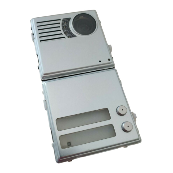
- Seite 1 Mod. 1083 DS 1083-002A LBT 8394 POSTO ESTERNO VIDEO SINTHESI VIDEO ENTRY PANEL SINTHESI POSTE EXTERNE VIDÉO SINTHESI MICROALTAVOZ VIDEO SINTHESI VIDEO-AUSSENSTELLE SINTHESI Sch./Ref. 1083/72...
- Seite 2 ITALIANO Il posto esterno video Sch. 1083/72 è dedicato al sistema 2Voice. È realizzato su meccanica Sinthesi a 2 moduli e prevede 2 tasti di chiamata. Avvitare le viti A INSTALLAZIONE PULSANTIERA 1. Installare il modulo all’altezza indicata. 2. Montare il telaio portamoduli sulla scatola incasso.
-
Seite 3: Descrizione Dei Morsetti
DESCRIZIONE DEI MORSETTI numero di posto esterno Impostare un numero da 0 a 3 se il posto esterno è principale (v. AUX) o da 0 a 31 se il posto esterno è LINE secondario secondo la fi gura seguente. Linea Bus entrante LINE •... -
Seite 4: Configurazione Avanzata
CONFIGURAZIONE AVANZATA Per accedere alla confi gurazione avanzata posizionare entrambi i rotary switch alla posizione 9. Tipo di Il posto esterno emette un avviso acustico ed accende il led giallo di segnalazione. Principale Secondaria Al termine delle operazioni riportare il posto esterno a riposo modifi cando la posizione di almeno uno dei postazione rotary switch. - Seite 5 • Premere il pulsante superiore del posto esterno (1° pulsante). • Posizionare il dip-switch ID a 1. • Premere il pulsante 3 del primo modulo tasti (5° pulsante) che viene così associato all’utente 0 della colonna 1. “B” • Posizionare il dip-switch ID a 2. •...
-
Seite 6: Panel Installation
• Ogni volta che viene premuto il pulsante androne (morsetti PA, CT). The video door unit Ref. 1083/72 is dedicated to 2Voice system. It is designed on 2-module Sinthesi style • Alla ricezione del comando apriporta pedonale di un posto interno in funzione della confi gurazione and is equipped with 2 call buttons. -
Seite 7: Description Of Terminals
DESCRIPTION OF TERMINALS LINE Bus line in LINE Positive for pedestrian crossing electric lock Negative for pedestrian crossing electric lock Fasten the screws A Control camera signal Reference for control camera signal Control camera signal 2 / video switch Reference for control camera signal 2 / video switch Output of device for deaf people Driveway electric lock activation Command for video switch... - Seite 8 door unit number Set a number from 0 to 3 if the door unit is a main unit (v. AUX) or from 0 to 31 if the door unit is a secondary unit as shown in the following fi gure. •...
-
Seite 9: Advanced Configuration
ADVANCED CONFIGURATION • Set the ID dip switch to 2. • Press fi rst button of the third button module (eleventh button) to associate user 0 of column 2 in this To go to advanced confi guration, put both the rotary switches on position 9. manner. -
Seite 10: Technical Specifications
DOOR ELECTRIC LOCK MANAGEMENT The door units have two terminals for managing the capacitance discharge and hold of the door electric lock (SE-, SE+). The electric lock is operated in the following cases: “B” • Whenever the hall button is pressed (terminals PA, CT). •... -
Seite 11: Installation Du Clavier
FRANÇAIS Le poste externe vidéo Sch. 1083/72 a été projeté exprès pour le système 2Voice. Il a été réalisé selon le modèle Sinthesi avec 2 modules et prévoit 2 touches d’appel. Visser les vis A INSTALLATION DU CLAVIER 1. Installer le module à la hauteur indiquée. -
Seite 12: Description Des Bornes
DESCRIPTION DES BORNES numéro du poste externe. Saisir un nombre de 0 à 3 si le poste externe est principale ou de 0 à 31 si le poste externe est secondaire LINE conformément à la fi gure suivante. Ligne Bus entrante LINE •... -
Seite 13: Configuration Avancée
CONFIGURATION AVANCÉE Pour accéder à la confi guration avancée, positionner les deux dip switch rotatifs sur 9. Le poste externe émet un signal acoustique et la led de signalisation jaune s’allume. Quand les opérations ont été complétées, Type de poste Principal Secondaire mettre de nouveau le système au repos en modifi... - Seite 14 • Accéder à la confi guration avancée. • Sortir de la confi guration avancée. • Positionner le micro-interrupteur ID sur 0. • Appuyer sur la touche en haut du poste externe (1ère touche). “B” • Positionner le micro-interrupteur ID sur 1. •...
-
Seite 15: Instalación Del Teclado
électrique (SE-, SE+). La serrure électrique est pilotée dans les cas suivants: El puesto exterior de vidéo Sch. 1083/72 es dedicado al sistema 2Voice. Es realizado con la mecánica • Chaque fois que la touche du hall d’entrée est actionnée (bornes PA, CT). -
Seite 16: Descripción De Los Bornes
DESCRIPCIÓN DE LOS BORNES LINE Línea Bus de entrada LINE Accionamiento positivo cerradura eléctrica peatonal Accionamiento negativo cerradura eléctrica peatonal Ajustar los tornillos A Señal telecámara de control Referencia para señal telecámara de control Señal telecámara de control 2 / conmutador vidéo Referencia para señal telecámara de control 2 / conmutador vidéo Salida dispositivo para personas con defecto de oído Accionamiento cerradura eléctrica vado permanente... - Seite 17 número del microaltavoz. Confi gurar un número del 0 al 3 si el microaltavoz es principal, o del 0 al 31 si es secundario, según la fi gura presentada más abajo. • No debe haber 2 puestos principales con el mismo ID; pueden coexistir 2 puestos secundarios con el mismo ID pero con distinta dirección (0 o 1).
-
Seite 18: Configuración Avanzada
CONFIGURACIÓN AVANZADA • Entrar en confi guración avanzada. • Colocar el interruptor dip ID en 0. Para acceder en la confi guración avanzada posicionar ambos los interruptores “rotary switch” en la posición • Accionar el pulsador superior del microaltavoz (1° pulsador). 9. -
Seite 19: Caracteristicas Tecnicas
• Reposicionar todos los interruptores switch en la posición original; ACCIONAMIENTO CERRADURA ELÉCTRICA PEATONAL • Salir de la confi guración de avance. Los microaltavoces tienen dos bornes para la gestión con descarga capacitiva de la cerradura eléctrica (SE-, SE+). “B” La cerradura eléctrica es activada en los siguientes casos: Posición de llamada secundaria con 8 teclas •... -
Seite 20: Installation Des Tastenfelds
DEUTSCH Die Videoaußenstelle Mod. 1083/72 ist dem System 2Voice gewidmet. Sie wird auf Mechanik Sinthesi mit 2 Modulen erzeugt und sieht 2 Ruftasten vor. Die Schrauben A anziehen INSTALLATION DES TASTENFELDS 1. Das Modul auf der angegebenen Höhe installieren. 2. Den Modulhalterrahmen auf das Einbaugehäuse montieren. -
Seite 21: Beschreibung Der Klemmen
BESCHREIBUNG DER KLEMMEN Nummer der Außenstelle. Eine Zahl von 0 bis 3 eingeben, wenn die Außenstelle eine Hauptstelle ist oder von 0 bis 31, wenn die LINE Außenstellen eine Nebenstelle wie in der Abbildung im Anschluss ist. Eingehende BUS-Leitung LINE •... -
Seite 22: Fortgeschrittene Konfiguration
FORTGESCHRITTENE KONFIGURATION Um auf die fortgeschrittene Konfi guration zugreifen, beide DIP-Drehschalter in Position ‘9’ bringen. Die Außenstelle sendet ein Tonsignal und schaltet die gelbe LED ein. Um die Außenstelle in die Ruhezustand- Art der Einheit Haupteinheit Nebeneinheit Position zurückzubringen, am Ende der Verfahren die Position von mindestens einem der DIP-Drehschalter verändern. -
Seite 23: Konfiguration Der Taste Für Spezialfunktion
• Die ID des Dip-Switches auf 0 positionieren. • Die obere Taste der Außenstelle betätigen (1. Taste). “B” • Die ID des Dip-Switches auf 1 positionieren. Nebenrufmodul mit 8 Tasten • Die Taste 3 des ersten Tastenmoduls betätigen (5. Taste), das so mit dem Teilnehmer 0 der Steigleitung ID = n AUX dip 2 = 1 1 assoziiert wird. -
Seite 24: Steuerung Der Elektroverriegelung Der Fussgänger-Eingang
STEUERUNG DER ELEKTROVERRIEGELUNG DER FUSSGÄNGER-EINGANG Die Außenstellen verfügen über zwei Klemmen für die Verwaltung der Elektroverriegelung über kapazitive Entladung (SE-, SE+). Die Elektroverriegelung wird in den folgenden Fällen gesteuert: • Jedes Mal beim Drücken der Taste der Eingangshalle (Klemmen PA, CT). •... - Seite 25 DS 1083-002A LBT 8394 FILIALI SEDE 20151 MILANO - V.Gallarate 218 URMET DOMUS S.p.A. Tel. 02.380.111.75 - Fax 02.380.111.80 10154 TORINO (ITALY) 00043 CIAMPINO (ROMA) V.L. Einaudi 17/19A VIA BOLOGNA 188/C Tel. 06.791.07.30 - Fax 06.791.48.97 Telef. +39 011.24.00.000 (RIC. AUT.) 80013 CASALNUOVO (NA) V.Nazionale delle Puglie 3...