Pecon CTI-Controller 3700 Handbuch
Inhaltsverzeichnis
Verfügbare Sprachen
Verfügbare Sprachen
Quicklinks
CTI-Controller 3700
German - English
Manual
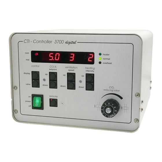
CTI-Contro l l er 3700
nom
5.0 2
real
control
setpo int
display
valve
remot e
on
power
off
Stabilization of the "
in vitro
for cell and tissue culture
37 °C
5.0 %
CO
2
7.0 %
O
2
tempcont rol 37-2
digital
° C
37.0
37.0
+
+
1
E
2
on
po wer
+
off
+
heater
2
nor mal
overheat
CO
%
vent i l ation
heating
2
speed
intensity
CO
2
reduci n g valve
environment"
L aminar
air flow
°C + CO
2
Inhaltsverzeichnis

Inhaltszusammenfassung für Pecon CTI-Controller 3700
- Seite 1 °C + CO Manual CTI-Controller 3700 tempcont rol 37-2 digital ° C 37.0 37.0 po wer CTI-Contro l l er 3700 heater 5.0 2 nor mal real overheat control vent i l ation heating speed intensity setpo int display valve...
- Seite 2 Die Kenntnis dieses Manuals ist notwendig zum Betrieb des Gerätes. Machen sie sich daher bitte mit dem Inhalt dieses Manuals vertraut und achten sie besonders auf Hinweise, die der sicheren Bedienung des Gerätes dienen. Änderungen, die dem technischen Fortschritt dienen, bleiben vorbehalten. Das Manual unterliegt keinem "Update-Service".
-
Seite 3: Technische Daten
Lufttemperierung und -Regelung am Mikroskop digital Kurzbeschreibung CTI-Controller 3700 heater 5.0 2 normal real • Das Gerät CTI-Controller 3700 dient der Versorgung der verschiedenen overheat control ventilation heating speed intensity setpoint Inkubatoren (siehe unten) mit einem temperierten CO -Luftgemisch. display... -
Seite 4: Montage
Manual: CTI-Controller 3700 Montage: Es wird nur der allgemeine Aufbau beschrieben, eine genauere Beschreibung findet sich im Manual des Inkubators bzw. des Inkubationssystems. Idealerweise wird das Gerät rechts neben dem Mikroskop aufgestellt. Das Tempcontrol-Regelgerät kann z.B. rechts auf den CTI-Controller gestellt werden. - Seite 5 Manual: CTI-Controller 3700 Anschluss der CO -Flasche outlets are usually connected (see manual Incubator) remote CO input output input ventilation out for external for internal 1 bar air filter RS 232 max 2 bar feeding feeding PU-tube, 4m sensor calibration...
-
Seite 6: Betrieb
Manual: CTI-Controller 3700 Betrieb digital CTI-Controller 3700 heater 5.0 2 normal real overheat control ventilation heating speed intensity setpoint display valve down down down reducing valve remote power CTI-Controller am Hauptschalter "power" (Vorderseite) einschalten. Das Gerät sollte eine Vorlauf- •... -
Seite 7: Remote-Betrieb
Adaptern nachgerüstet werden. Bitte setzen Sie sich hierzu mit ihrem Systemadministrator oder dem Computer-Fachhandel in Verbindung. • Laden Sie die Software „IRC – Incubation Remote Control“ aus dem Supportbereich der PeCon- Homepage unter http://support.pecon.biz herunter und installieren Sie diese. Wartung... - Seite 8 Manual: CTI-Controller 3700 Lampenwechsel Erscheint im Display eine dauerhafte CO -Anzeige von "HI" (> 10.2 % CO ), so ist ein Lampen- Austausch in der Infrarot-Sensor-Einheit notwendig. Die Ersatzlampe ist im Lieferumfang enthalten. Das Ersatz-Lampenmodul (# 0420.316) ist mit Klebeband innen an der Gerätefront befestigt.