Herunterladen Inhalt Inhalt Diese Seite drucken
Inhaltsverzeichnis

Werbung

Verfügbare Sprachen

Verfügbare Sprachen

Bedienungsanleitung
Installation instructions
Mode d'emploi
ISDN-TE-Hub home 1/4
V 1.0

Werbung

Inhaltsverzeichnis
loading

Inhaltszusammenfassung für BTR ISDN-TE-Hub home 1/4

  • Seite 1 Bedienungsanleitung Installation instructions Mode d’emploi ISDN-TE-Hub home 1/4 V 1.0...
  • Seite 2 Bedienungsanleitung ISDN-TE-Hub home 1/4 Aktiver Sternverteiler zum Anschluss mehrerer ISDN-Endgeräte an einen ISDN-Anschluss bei sternförmiger Verkabelung V 1.0...
  • Seite 4: Inhaltsverzeichnis

    Funktionsbeschreibung ........D9 Leuchtanzeigen am ISDN-TE-Hub home 1/4 .....D9 Hintereinanderschaltung von ISDN-TE-Hubs .
  • Seite 5: Einleitung

    1. Einleitung Sehr geehrter Kunde, wir bedanken uns für den Kauf des ISDN-TE-Hub home 1/4. Mit diesem Gerät haben Sie ein Produkt erworben, welches nach dem aktuellsten Stand der Technik gebaut wurde. Dieses Produkt erfüllt die Anforderungen der geltenden europäischen und natio- nalen Richtlinien.
  • Seite 6: Wichtige Hinweise

    Haftung. In solchen Fällen erlischt jeder Garantieanspruch. Aus Sicherheits- und Zulassungsgründen (CE) ist das eigenmächtige Um- bauen und / oder Verändern des ISDN-TE-Hub home 1/4 nicht gestattet. Als Spannungsquelle für das Steckernetzteil darf nur eine ordnungsgemäße Netzsteckdose (230 V / 50 Hz) des öffentlichen Versorgungsnetzes verwendet werden.
  • Seite 7: Bestimmungsgemäße Verwendung

    Die Verwendung ist nur in geschlossenen Räumen, also nicht im Freien erlaubt. Das Gerät darf nur über das von BTR IT CONNECT mitgelieferte Stecker- netzteil an 230 V / 50 Hz angeschlossen werden. Eine andere Verwendung als zuvor beschrieben kann zur Beschädigung dieses Produkts führen, außerdem ist dies mit Gefahren, wie z.
  • Seite 8: Allgemeine Informationen

    3. Allgemeine Informationen 3.1 Allgemeine Informationen Für ISDN ist wie für die meisten digitalen Übertragungstechniken die bus- förmige Verkabelung der Endgeräte festgelegt. Dies bedeutet, dass alle Endgeräte nacheinander an einer Leitung angeschlossen sind. NTBA Anschlussdose 1 Anschlussdose 2 Anschlussdose 3 Anschlussdose 4 Diese Form der Zusammenschaltung von Endgeräten war zur Entstehungs- zeit von ISDN zwar die einfachste und gängigste Technik, jedoch entspricht...
  • Seite 9 Leitungen durch Verwendung von passiven Sternverteilern als Bus zu verschalten, wodurch die maximale übliche ISDN-Bus-Leitungslänge schnell überschritten wird. Mit dem ISDN-TE-Hub home 1/4 lösen Sie auf sehr einfache Weise und ohne kostenintensiven Montage- oder Installationsaufwand dieses Problem ohne Einschränkungen in der Funktion.
  • Seite 10: Funktions- Und Gerätebeschreibung

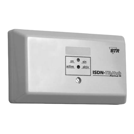
    Umrüstungen und Modernisierungen einsetzbar. 4.2 Leuchtanzeigen am ISDN-TE-Hub home 1/4 In der Gehäusemitte des ISDN-TE-Hub home 1/4 sind zwei Leuchtdioden angebracht. Die grüne Leuchtdiode leuchtet, sobald der ISDN-TE-Hub home 1/4 über das Steckernetzteil mit Strom versorgt wird. Die rote Leuchtdiode leuchtet auf, sobald die ISDN-S -Schnittstelle aktiviert ist und Signale über-...
  • Seite 11: Gerätebeschreibung

    4. Funktions- und Gerätebeschreibung 4.4 Gerätebeschreibung DIP-Schalter zur Aktivierung / Deaktivierung der Abschlusswiderstände...
  • Seite 12: Montage Und Inbetriebnahme

    Der ISDN-TE-Hub home 1/4 kann je nach Anforderungen entweder als Tischgerät eingesetzt oder an die Wand geschraubt werden. Zur Aufputz- montage schrauben Sie den Deckel des ISDN-TE-Hub home 1/4 ab. Nun sind die beiden Öffnungen zum Anzeichnen der Bohrlöcher und zum Festschrauben des Geräts zugänglich.
  • Seite 13 ISDN-TE-Hub home 1/4, schließen Sie den Gehäusedeckel und stecken Sie das Steckernetzteil in eine 230 V Steckdose. Sobald der ISDN-TE-Hub home 1/4 über das Steckernetzteil mit Strom versorgt wird, leuchtet die grüne LED und die ISDN-Installation ist damit betriebsbereit.
  • Seite 14 5. Montage und Inbetriebnahme optionaler Anschluss oder Weiterführung des ISDN S -Busses NTBA 230 V ISDN S -Bus...
  • Seite 15: Abschlusswiderstände

    -Bus-Installationen gilt die Grundregel, dass der ISDN-S -Bus am Anfang und am Ende mit 100-Ohm-Abschlusswiderständen abgeschlossen werden muss. Die Ausgänge A1 bis A4 des ISDN-TE-Hub home 1/4 sind als eigenständige ISDN-Busse zu betrachten. Die Widerstände am Busanfang dieser Ausgänge sind im ISDN-TE-Hub home 1/4 integriert. Die Abschlusswiderstände am Busende sind bei der Montage in die ISDN-...
  • Seite 16 5. Montage und Inbetriebnahme Der ISDN-TE-Hub home 1/4 ist ohne Programmierung sofort funktions- bereit. Die integrierten Abschlusswiderstände am Eingang des ISDN-TE-Hub home 1/4 werden im Bedarfsfall durch Schalten der auf der Leiterplatte befind- lichen DIP-Schalter in Stellung “On” aktiviert. Hinweis: Als Abschlusswiderstände in den Anschlussdosen können z. B. die ISDN-Adapter von BTR IT CONNECT verwendet werden.
  • Seite 17: Wartung Und Entsorgung

    6. Wartung und Entsorgung 6.1 Wartung Reinigen Sie den ISDN-TE-Hub 1/4 home nur von außen und nur mit einem feuchten Tuch. Keine scharfen Reinigungsmittel verwenden! Eindringende Feuchtigkeit kann zu Kurzschlüssen und damit zur Zerstörung des Geräts führen. 6.2 Entsorgung Entsorgen Sie das Gerät gemäß den zur Zeit geltenden gesetzlichen Vorschriften.
  • Seite 18: Behebung Von Störungen

    Netzteil nicht stellen, bzw. Netzteil gesteckt einstecken ISDN-Endgeräte Fehler in der Verkabelung Verkabelung kontrollieren funktioniert nicht evtl. Direktanschluss ohne ISDN-TE-Hub home 1/4 testen, Leitungslängen kontrollieren Nur Endgeräte ISDN-Anschluss im Notbetrieb, Speisung des ISDN- mit eigener Speisung ungespeister S -Bus,...
  • Seite 19: Technische Daten

    8. Technische Daten 8.1 Technische Daten Steckernetzteil: Eingang: 230 V / 50 Hz Ausgang: 9 V AC / 130 mA ISDN-Schnittstelle: nach ITU-T I.430 / ETS 300012 8.2 Umgebungsbedingungen Umgebungstemperatur:-10 °C ... +50 °C Rel. Luftfeuchtigkeit: max. 85 %...
  • Seite 20: Garantie

    9. Garantie 9.1 Garantie Für Garantie und Gewährleistungen gelten unsere allgemeinen Verkaufs-und Lieferbedingungen.
  • Seite 21: Konformitätserklärung

    10. Konformitätserklärung...
  • Seite 22: Installation Instructions

    Installation instructions ISDN-TE-Hub home 1/4 active star type distributor to connect several ISDN terminals to one ISDN connection by using star type cabling V 1.0...
  • Seite 24 Functional description ........E9 LEDs at the ISDN-TE-Hub home 1/4 ......E9 Series connection of ISDN-TE hubs .
  • Seite 25: Introduction

    1. Introduction Dear customer, we thank you for buying the ISDN-TE-Hub home 1/4. By purchasing this device you have decided for a product manufactured according to the latest state-of the art. This product meets the requirements of the current european and national regu- lations.
  • Seite 26: Important Notes

    Before opening the housing cover detach the device from all cables and supply lines. Do not touch the pc board to avoid any damage of ISDN-TE-Hub home 1/4 components. Please take care that the ISDN-TE-Hub home 1/4 is plugged to a near by and easily accessible wall outlet.
  • Seite 27: Intended Use

    We decline liability for any consequential damages! 2.2 Intended use The ISDN-TE-Hub home 1/4 works only at an ISDN S attachment according to ITU-T1.430 / ETS 300012 For indoor use only, no outdoor use allowed.
  • Seite 28: General Information

    3. General information 3.1 General information ISDN same as the most digital transfer modes require bus type cabling for terminal equipment. This means that all terminals are connected in series to one line. NTBA wall outlet 1 wall outlet 2 wall outlet 3 wall outlet 4 In the beginning of ISDN this kind of connecting terminal equipment has...
  • Seite 29: General Information

    ISDN bus cable length. The ISDN-TE-Hub home 1/4 solves this problem quite easily and without cost intensive mounting or installation work and without reducing functio- nal features.
  • Seite 30: Description Of Function And Device

    4.2 LEDs at the ISDN-TE-Hub home 1/4 In the middle of the ISDN-TE-Hub home 1/4 housing are two LEDs. The green LED lights up as soon as the ISDN-TE-Hub home 1/4 gets powered by the power supply. The red LED lights up when the ISDN S interface is acti- vated and signals are transferred.
  • Seite 31: Description Of Device

    4. Description of function and device 4.4 Description of device DIP switch to activate or deactivate the terminating resistors...
  • Seite 32: Mounting And Startup Procedure

    5. Mounting and startup procedure 5.1 Mounting The ISDN-TE-Hub home 1/4 is designed for desk-top use or wall fixing. First unscrew and remove the cover of the ISDN-TE-Hub home 1/4. Now, you have access to the two apertures to mark the drill holes and screw the devi- ce on the wall.
  • Seite 33 Plug the male connector of the power supply cable into the power supply port of the ISDN-TE-Hub home 1/4, close the housing cover and plug the power supply into a 230 V supply outlet. As soon as the ISDN-TE-Hub home 1/4 is powered the green LED lights up and the ISDN installation is ready to start.
  • Seite 34 5. Mounting and startup procedure optional connection or extension of the ISDN S NTBA 230 V ISDN S...
  • Seite 35: Terminating Resistors

    100 Ohm terminating resistors. The outputs A1 to A4 of the ISDN-TE-Hub home 1/4 are to consider as independent ISDN busses. The resistors at the beginning of the bus of these outputs are integrated to the ISDN-TE-Hub home 1/4.
  • Seite 36 5. Mounting and startup procedure The ISDN-TE-Hub home 1/4 is ready to start work without programming. The integrated terminating resistors at the ISDN-TE-Hub home 1/4 input are activated if necessary by setting the DIP switch on the pc board to position “ON”.
  • Seite 37: Maintenance And Product Disposal

    6. Maintenance and product disposal 6.1 Maintenance Clean the ISDN-TE-Hub 1/4 home only from the outside by using a moist cloth. Do not use any sharp cleaning agents! Incoming moisture may cause short circuits and result in the destruction of the device. 6.2 Product disposal The ultimate disposal of this device should be handled according to all natio- nal laws.
  • Seite 38: Trouble Repair

    7. Trouble repair 7.1 Trouble repair Trouble possible reason trouble repair the green LED supply of power pack is inter- ensure power supply does not light rupted or power pack not and/or plug power pack plugged ISDN terminals cabling error check cabling, if necessary do not work check direct connection...
  • Seite 39: Technical Data

    8. Technical Data 8.1 Technical data power pack: input: 230 V / 50 Hz output: 9 V AC / 130 mA ISDN interface: according to ITU-T I.430 / ETS 300012 8.2 Environmental conditions Ambient temperature: -10 °C to +50 °C Rel.
  • Seite 40: Guarantees And Warranties

    9. Guarantees and warranties 9.1 Guarantees and warranties Our general terms for sales and delivery are applicable for any guarantee and warranty.
  • Seite 41: Declaration Of Conformity

    10. Declaration of conformity...
  • Seite 42 Instructions de service ISDN-TE-Hub home 1/4 Distributeur actif en étoile pour raccorder plusieurs terminaux RNIS à une terminsaison réseau RNIS avec câblage en étoile V 1.0...
  • Seite 44 ........F9 Indications lumineuses du ISDN-TE-Hub home 1/4 ....F9 Raccordement en série de plusieurs ISDN-TE-Hub...
  • Seite 45: Introduction

    Ce produit répond aux directives européennes et nationales en vigueur. Sa confor- mité a été prouvée, les déclarations et documents correspondants sont archivés chez BTR IT CONNECT. 1.1 Contenu de livraison ISDN-TE-Hub home 1/4 câble de raccordement RNIS...
  • Seite 46: Indications Importantes

    Cela provoquera une expiration de tout droit à une garantie. Pour des raisons de sécurité et d’homologation (CE) toute transformation ou modification de sa propre autorité du ISDN-TE-Hub home 1/4 est interdite. Utiliser pour le bloc d’alimentation uniquement une prise de réseau réglementaire (230 V / 50 Hz) du réseau d’alimentation public.
  • Seite 47: Emploi Conformément Aux Dispositions

    Nous déclinons toute responsabilité pour d'éventuels dommages indirects! 2.2 Emploi conformément aux dispositions Le ISDN-TE-Hub home 1/4 fonctionne uniquement à une connexion RNIS selon ITU-T1.430 / ETS 300012 L'emploi est autorisé uniquement dans des locaux, mais non à l'extérieur.
  • Seite 48: Informations Générales

    3. Informations générales 3.1 Informations générales Comme pour la plupart des modes de transmission digitale le câblage en bus des postes terminaux est aussi prévu pour le RNIS. Cela signifie que tous les terminaux sont raccordés en ligne. terminaison réseau RNIS boîte de connexion 1 boîte de connexion 2 boîte de connexion 3...
  • Seite 49: Informations Générales

    étoile passifs pour connecter les lignes en étoile en bus, mais avec cette méthode on dépassait rapidement la longueur du bus RNIS habituelle. Le ISDN-TE-Hub home 1/4 vous permet de résoudre ce problème facilement, sans efforts de montage ou d'installation coûteux et sans restrictions quel- conques dans le fonctionnement.
  • Seite 50: Description De La Fonction Et De L'appareil

    4. Description de la fonction et de l’appareil 4.1 Description de la fonction Le ISDN-TE-Hub home 1/4 permet de raccorder plusieurs liaisons en étoile à une boîte RNIS soit en série avec une installation de télécommunication ou directement au poste réseau. On peut utiliser du matériel habituel RNIS comme des boîtes de connexion RNIS et des câbles d’installation RNIS.
  • Seite 51: Description De L'appareil

    4. Description de la fonction et de l’appareil 4.4 Description de l’appareil commutateur DIP pour activer / déactiver les résistances terminales...
  • Seite 52: Montage Et Mise En Service

    5. Montage et mise en service 5.1 Montage Le ISDN-TE-Hub home 1/4 se laisse utiliser en poste de table ou il peut être fixé au mur. Pour le montage mural dévissez le couvercle du ISDN-TE-Hub home 1/4. Maintenant vous avez accès aux deux ouvertures qui permettent de marquer les trous à...
  • Seite 53 Mettez la fiche du câble d'alimentation dans la prise d'alimentation du ISDN- TE-Hub home 1/4, fermez le couvercle du boîtier et raccordez le bloc d'alimentation à une fiche de 230 V. Dès que le ISDN-TE-Hub home 1/4 est alimenté par le bloc d'alimentation l’indication verte s'allume et l'installation...
  • Seite 54 5. Montage et mise en service prise supplémentaire pour raccord facultatif ou passage du bus RNIS S terminaison réseau RNIS 230 V bus S RNIS...
  • Seite 55 RNIS. La terminaison de l'entrée du ISDN-TE-Hub home 1/4 n'est pas nécessaire si on utilise le câble RNIS inclus. Si le ISDN-TE-Hub home 1/4 est installé par l’intermédiaire de câbles d'installation aux blocs de jonction il faut activer les résistance terminales intégrées.
  • Seite 56 Les résistances terminales intégrées aux entrées du ISDN-TE-Hub home 1/4 se laissent activer au besoin en mettant les commutateurs DIP en position “ON”. Note: On peut utiliser les adaptateurs RNIS de BTR IT CONNECT comme rési- stances terminales dans les boîtes de connexion. Référence 130820-I. résistances terminales activées résistances terminales déactivées...
  • Seite 57: Entretien Et Traitment De Déchets

    6. Entretien et traitment de déchets 6.1 Entretien Nettoyez le ISDN-TE-Hub 1/4 home seulement de l'extérieur et uniquement avec un chiffon humide. Ne pas utiliser de nettoyant corrosif. De l'humidité entrant dans l'intérieur du boîtier peut causer des court-circuits et ainsi détruire l'appareil.
  • Seite 58: Remédier Des Dérangements

    éventuellement le raccord direct sans ISDN-TE-Hub home 1/4 vérifier la longueur des câbles Seulement les termi- terminaison réseau RNIS en service assurer l’alimentation du naux avec alimenta- de secours, bus S non alimenté,...
  • Seite 59: Données Techniques

    8. Données techniques 8.1 Données techniques Bloc d’alimentation: entrée: 230 V / 50 Hz sortie: 9 V AC / 130 mA Interface RNIS: selon ITU-T I.430 / ETS 300012 8.2 Conditions ambiantes Température ambiante: -10 °C ... +50 °C Humidité de l’air relative: max.
  • Seite 60: Garanties

    9. Garanties 9.1 Garanties Nos conditions générales applicables aus ventes et livraisons sont valables pour toute garantie.
  • Seite 61: Déclaration De Conformité

    10. Déclaration de conformité...
  • Seite 62 +49 7702 535-690 direct fax +49 7702 535-691 Pour des questions de fonction- nement notre service technique Produktspezifische FAQs sera à votre disposition. unter www.btr-itconnect.com tél. +49 7702 535-690 fax direct +49 7702 535-691 062004/1.000/02/B/899 838-01...

Inhaltsverzeichnis