
Verwandte Anleitungen für Zehnder Pumpen ZFS 71.1 W Ex


Inhaltszusammenfassung für Zehnder Pumpen ZFS 71.1 W Ex
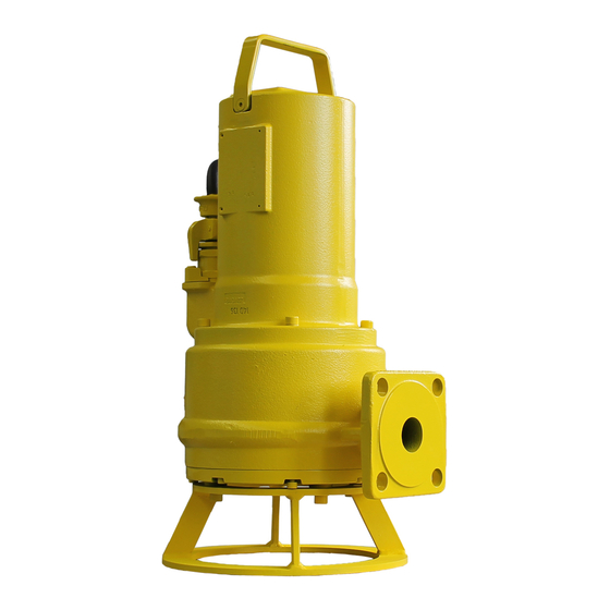
- Seite 1 Abwasser-Tauchpumpe Grinder pump ZFS 71 Ex ZFS 71 Ex Betriebsanleitung / operation manual...
-
Seite 2: Inhaltsverzeichnis
Inhalt: Seite Konformitätserklärung ..................3 1. Allgemeines......................4 1.1 Zugehörigkeit ....................4 1.2 Anfragen und Bestellungen ................4 1.3 Technische Daten ..................4 1.4 Einsatzbereich ..................... 5 1.5 Zubehör ....................... 5 2. Sicherheit ......................5 2.1 Kennzeichnung von Hinweisen in der Betriebsanleitung ......6 2.2 Personalqualifikation .................. -
Seite 3: Konformitätserklärung
Konformitätserklärung ------------------------------------------------------------------------------------------------------------------------------ Hiermit erklären wir, die ZEHNDER Pumpen GmbH Zwönitzer Strasse 19 08344 Grünhain-Beierfeld, dass die Abwasser-Tauchpumpen Typ ZFS 71 II 2G EEx d IIB T3 folgenden einschlägigen Bestimmungen entsprechen: folgenden einschlägigen Richtlinien entsprechen: - EG-Niederspannungsrichtlinie 2014/35 EU - EMV-Richtlinie 2014/30/EU - Maschinenrichtlinie 2006/42/EG Angewendete übereinstimmende Normen, insbesondere... -
Seite 4: Allgemeines
Defekten oder Schadensfällen wenden Sie sich bitte an Ihren Händler. Hersteller: ZEHNDER Pumpen GmbH Zwönitzer Strasse 19 08344 Grünhain-Beierfeld Baugrössen: ZFS 71.1 W Ex ZFS 71.1 D Ex ZFS 71.2 D Ex ZFS 71.3 D Ex ZFS 71.4 D Ex Stand der Betriebsanleitung: Januar 2013 Prüfungen/Abnahmen:... -
Seite 5: Einsatzbereich
Werkstoffe: Motorgehäuse....GG 20 Laufrad......GG 20 Motorwelle ....1.4021 Schneidmesser .....1.4112 Pumpengehäuse...GG 20 Lagerhilfsflansch...St 37-2 Lagerflansch ....GG 20 Gleitringdichtungen..SiC (Siliziumkarbid) Schneidflansch .....1.4112 Sonstige Dichtungen..NBR, FPM 1.4 Einsatzbereich Die Abwasser-Tauchpumpen Typ ZFS 71 II 2G EEx d IIB T3 dienen zur Entwässerung von Schmutz- und Abwasserschächten, Fäkaliensammelgruben, Kläranlagen u.ä. -
Seite 6: Kennzeichnung Von Hinweisen In Der Betriebsanleitung
2.1 Kennzeichnung von Hinweisen in der Betriebsanleitung Die in dieser Betriebsanleitung enthaltenen Sicherheitshinweise, die bei Nichtbeachtung Gefährdungen für Perso- nen hervorrufen können, sind mit allgemeinem Gefahrensymbol Sicherheitszeichen nach DIN 4844 - W 9, bei Warnung vor elektrischer Spannung mit Sicherheitszeichen nach DIN 4844 - W 8 besonders gekennzeichnet. -
Seite 7: Sicherheitshinweise Für Wartungs-, Inspektions- Und Montagearbeiten
- Leckagen (z.B. der Wellendichtung) gefährlicher Fördergüter (z.B. explosiv, giftig, heiß) müssen so abgeführt werden, dass keine Gefährdung für Personen und Umwelt entsteht. Gesetzliche Bestimmungen sind einzuhalten. - Gefährdungen durch elektrische Energie sind auszuschließen (Einzelheiten hierzu siehe z.B. in den Vorschriften des VDE und der örtlichen Energieversorgungsunternehmen). -
Seite 8: Beschreibung
4. Beschreibung 4.1 Motoren Die Pumpen ZFS 71 II 2G EEx d IIB T3 sind mit einem Wechsel- bzw. Drehstrom-Asynchronmotor ausgestat- tet. In jede der drei Motorwicklungen sind 2 Temperaturfühler (Bi-Metall) integriert, die als Temperaturregler bzw. Temperaturbegrenzer (Öffner) arbeiten. Wird der Motor aus irgendeinem Grund zu heiß, so spricht zuerst der Temperaturregler an und schaltet den Motor ab. - Seite 9 Eine weitere elektrische Installation ist nicht notwendig. Bei Bedarf kann das Motorgehäuse an der dafür vorgese- henen externen Erdungsklemme zusätzlich geerdet werden. Wird ein Schaltgerät an die Pumpe ZFS 71.1 W Ex angeschlossen, so erfolgt der Anschluss wie folgt: Motor...
-
Seite 10: Hydraulik
Anschlussplan Drehsrommotor: Motor 3∼ ∼ ∼ ∼ 1 (U1) 2 (V1) 3 (W1) 5 (TB2) 4 (TB1) 6(TB3) grün/gelb (PE) (Bezeichnungen des Motorkabels) Regelkreis M o t o r s c h u t z Schutzleiter L e i s t u n g s s c h ü t z B e g r e n z e r k r e i s N e t z 4 0 0 V Anschuss des thermischen Wicklungsschutzes... -
Seite 11: Niveauregulierung
Aufstellung für Schachteinbau:- Rohrspanner am Schachtinnenrand positionieren und mit zwei Schrauben lose fixieren. - Position der Führungsrohraufnahme des Kupplungsfußes ausloten, Kupplungsfuß am Schachtboden ausrichten und mit den mitgelieferten Schwerlastdübeln montieren. - Druckleitung und Armaturen spannungsfrei installieren. - Führungsrohr auf Kupplungsfuß aufstecken, auf richtige Länge ab- sägen, Rohrspanner aufstecken und endgültig festschrauben. -
Seite 12: Störungen; Ursachen Und Beseitigung
8. Störungen; Ursachen und Beseitigung - Vor allen Arbeiten an der Anlage ist der Netzstecker zu ziehen. Störung Ursache Behebung 1. Motor dreht sich nicht - Netzspannung fehlt bzw. falsch - Spannungsversorgung überprüfen - fehlerhafter Anschluss - Anschluss korrigieren - defektes Stromkabel - Austausch (Kundendienst) - defekter/falscher Kondensator - Austausch (Kundendienst) -
Seite 13: Kennlinien
11. Kennlinien 12. Einbaubeispiele 12.1 Schachteinbau mit Führungsrohr 12.2 Aufstellung mit Bodenstützring 1a Kupplungsfuß 1b Führungsstück Rohrspanner Flanschkrümmer ″ Führungsrohr Rückflußverhinderer Keilflachschieber Ablasskette mit Schäkel Bodenstützring Druckleitung... -
Seite 14: Pumpenabmessungen
13. Pumpenabmessungen 13.1 Schachteinbau mit Führungsrohr 13.2 Aufstellung mit Bodenstützring 13.3 Einstellwerte für Schneidspalt und Pumpenhydraulik... -
Seite 15: Schnittzeichnung Und Ersatzteilliste
14. Schnittzeichnung und Ersatzteilliste... -
Seite 16: Ersatzteilliste
Tragegriff 10666 Innensechskantschraube M6x12-A2 DIN 912 17375 Passscheibe 10x30x0,1 1.4301 17376 Passscheibe 10x30x0,5 1.4301 11656 O-Ring 125x2-NBR70 11646 Dichtring 17x22x1,5 Cu für Pos 230 11645 Sperrzahnscheibe S8x13x0,8 A2 11690 Wisura technisches Weissöl NFW 0,4 l _____________________________________________________________________________________ ©2013 ZEHNDER Pumpen GmbH... - Seite 17 Table of contents: page Declaration of conformity..................18 1. General ......................19 1.1 Scope ......................19 1.2 Enquiries and orders .................. 19 1.3 Technical data.................... 19 1.4 Range of application .................. 20 1.5 Accessories ....................20 2. Safety......................... 20 2.1 Marking of the notes contained in the operation manual ......21 2.2 Personnel development ................
-
Seite 18: Declaration Of Conformity
Declaration of conformity --------------------------------------------------------------------------------------------------------------- We, the Zehnder Pumpen GmbH Zwönitzer Straße 19 08344 Grünhain-Beierfeld, herewith declare that the submersible waste water pumps of the type series ZFS 71 II 2G EEx d IIB T3 conform to the following relevant regulations:... -
Seite 19: General
The manufacturer assumes no liability for damages resulting from such behaviour! Manufacturer: Zehnder Pumpen GmbH Zwönitzer Straße 19 08344 Grünhain-Beierfeld Manufactured sizes: ZFS 71.1 W Ex ZFS 71.1 D Ex ZFS 71.2 D Ex ZFS 71.3 D Ex ZFS 71.4 D Ex... -
Seite 20: Range Of Application
Materials: Motor housing ....GG 20 Motor shaft.......1.4021 Pump housing....GG 20 Bearing flange ....GG 20 Cutting flange…....1.4112 Impeller......GG 20 Cutting knife…....1.4112 Other seals ......NBR, FPM Auxiliary bearing flange St 37-2 Floating-ring type shaft seal..SiC (silicon carbide) 1.4 Range of application The submersible waste water pumps of the type series ZFS 71 II 2G EEx d IIB T3 are used for the drainage of sewage and wastewater shafts, excrement collection pits, sewage plants and the like in explosion-prone areas. -
Seite 21: Marking Of The Notes Contained In The Operation Manual
2.1 Marking of the notes contained in the operation manual The safety notes contained in this operation manual which can cause danger to persons are specially marked by the following general danger symbol: Safety sign according to DIN 4844 - W 9, The following symbol warns against dangers caused by voltage Safety sign according to DIN 4844 - W 8 In case of safety notes the non-observance of which can cause danger to the machine and its functioning, the word... -
Seite 22: Safety Notes For The Operator/User
2.5 Safety notes for the operator/user - Hot or cold machine components which could cause danger have to be secured against contact by the customer. - Protection against accidental contact for moving parts (e.g. coupling) must not be removed while the machine is operating. -
Seite 23: Description
4. Description 4.1 Motors The pumps ZFS 71 II 2G EEx d IIB T3 are equipped with an AC asynchronous induction motor or a three- phase asynchronous motor. Temperature sensors, which function as temperature limiters, have been integrated into each of the three motor windings. If the motor overheats for any reason, the bimetallic contacts respond to this and the motor is switched off. - Seite 24 If an additional switching device is connected to the pump ZFS 71.1 W Ex, it has to be connected as follows: motor 230V U1 +Z2 2 (U2) 3 (Z1) 5 (T2) 4 (T1) 6(T3) green/yellow (PE) (designations of the motor cable) Capacitor 60µF...
- Seite 25 Wiring diagram three phase AC motor: motor 3∼ ∼ ∼ ∼ 1 (U1) 2 (V1) 3 (W1) 5 (T2) 4 (T1) 6(T3) green/yellow (PE) (designations of the motor cable) control loop motor protection earth wire c o n t a c t o r c l i p p i n g c i r c u i t m a i n s 4 0 0 V Connection of the thermal winding cover...
-
Seite 26: Hydraulic System
5.2 Hydraulic system These pumps are not to be mounted in dry installation, since a minimum water level up to the bottom edge of the motor housing is prescribed by the guideline on protection against explosion. Installation with supporting ring:-Mount supporting ring to intake flange of the pump and install pump. Ensure stability of the pump. -
Seite 27: Malfunctions; Causes And Elimination
Malfunctions; causes and elimination - Disconnect the power supply before carrying out any kind of work on the plant! Malfunction Cause Elimination 1. Motor is not rotating - absence of line voltage or improper - check voltage supply line voltage - incorrect connection - correct the connection - defective power cable... -
Seite 28: Characteristic Curves
11. Characteristic curves 12. Installation suggestions 12.1 Fixed installation 12.2 Portable installation 1a Coupling pedestal 1b Guide piece Pipe clamp Flange elbow ″ Guide pipe Backflow preventer Wedge-type flat slide valve Lowering chain with clevis Supporting ring Elbow 90° , G2 AG Pressure pipe... -
Seite 29: Pump Dimensions
13. Pump dimensions 13.1 Fixed installation 13.2 Portable installation 13.3 Adjustment values for cutting gap and pump hydraulics... -
Seite 30: Sectional Drawing And List Of Spare Parts
14. Sectional drawing and list of spare parts... - Seite 31 17375 Shim ring 10x30x0,1 1.4301 17376 Shim ring 10x30x0,5 1.4301 11656 O-ring 125x2-NBR70 11646 Sealing ring 17x22x1,5 Cu für Pos 230 11645 Tooth lock disc S8x13x0,8 A2 11690 Wisura technical white oil NFW 0,4 l _______________________________________________________________________________________________ ©2014 Zehnder Pumpen Gm...