Herunterladen Inhalt Inhalt Diese Seite drucken
Hazet 2152-5 Betriebsanleitung

Hazet 2152-5 Betriebsanleitung

Elektrisches multifunktions-prüfgerat
Inhaltsverzeichnis

Werbung

Verfügbare Sprachen

Verfügbare Sprachen

HAZET-WERK
HÖCHSTE TECHNOLOGIE IN DER WERKZEUGFERTIGUNG SEIT 1868
HIGHEST TECHNOLOGY IN TOOL MANUFACTURE SINCE 1868
2152-5
Betriebsanleitung
Elektrisches Multifunktions-Prüfgerät
Operating Instructions
Electrical Multifunctional Testing Device
Notice d'utilisation
Testeur électronique multifonctionnel

Werbung

Inhaltsverzeichnis
loading

Inhaltszusammenfassung für Hazet 2152-5

  • Seite 1 HAZET-WERK HÖCHSTE TECHNOLOGIE IN DER WERKZEUGFERTIGUNG SEIT 1868 HIGHEST TECHNOLOGY IN TOOL MANUFACTURE SINCE 1868 2152-5 Betriebsanleitung Elektrisches Multifunktions-Prüfgerät Operating Instructions Electrical Multifunctional Testing Device Notice d’utilisation Testeur électronique multifonctionnel...
  • Seite 2: Inhaltsverzeichnis

    Funktion Überbrückungskabel ......................15 Überprüfung eines schlechten Massekontakts ................16 Kurzschlüsse verfolgen und lokalisieren ..................16 Durchbrennen von Sicherung vermeiden ..................17 18–32 Table of Contents Operating Instructions HAZET 2152-5 Page Lighting and audible signal .......................22 Connecting and Self-Testing ......................23 Polarity Test ............................24 Continuity Test ..........................25 Activating components of the electrical system of the car .............26...
  • Seite 3: Zu Ihrer Information

    • Dieses Prüfgerät wurde für bestimmte • Ansprüche jeglicher Art gegen den Hersteller An wendungen entwickelt. HAZET weist aus- und/oder seine Bevollmächtigten wegen drücklich darauf hin, dass dieses Prüfgerät Schäden aus nicht bestimmungsgemäßer nicht verändert und/oder in einer Weise ein- Verwendung des Gerätes sind ausgeschlos-...
  • Seite 4: Allgemeines

    Regeln der Technik gebaut ten. und gilt als betriebssicher. Es können vom Die Benutzung und Wartung von HAZET- Prüfgerät jedoch Gefahren ausgehen, wenn Prüfgeräten muss immer entsprechend den es von nicht fachgerecht ausgebildetem lokalen staatlichen Landes- oder Bundes- Per sonal, unsachgemäß...
  • Seite 5 Zu Ihrer Information Das elektrische Mutifunktions-Prüfgerät HAZET Das HAZET-Prüfgerät darf NICHT 2152-5 ist ein Testgerät zur Verkürzung der mit 110/230 Volt-Netzspannung ver- Diagnosezeit für elektrische Kfz-Systeme wendet werden. HAZET- von 12...24 Volt. Nach dem Anschluss des Prüfgerät 2152-5 ist ausschließlich Prüfgerätes an der Fahrzeugbatterie kann...
  • Seite 6: Aufbau Und Funktion

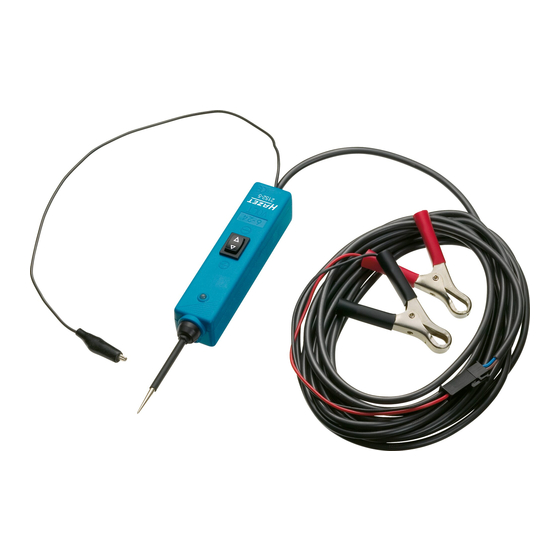
    Aufbau und Funktion negative Hilfsklemme Licht Prüf- spitze rot/grün Reset- Schalter Akustisches Signal Wippschalter Klemmen rot/schwarz Nicht an Motorsteuergeräten verwenden! Nicht an Motorsteuergeräten verwenden!
  • Seite 7: Beleuchtung Und Akustisches Signal

    Aufbau und Funktion Multifunktions-Prüfgerät 2152-5 mit Beleuchtung und akustischer Signalfunktion HAZET 2152-5 ist mit Beleuchtung und einer akustischen Signal funktion ausgestattet. Wenn es an eine funk tions tüchtige Batterie ange- schlossen wird, werden Be leuchtung und Signal funk tion aktiviert.
  • Seite 8: Anschluss Und Selbsttest

    Aufbau und Funktion Anschluss Das Prüfgerät wird bei Beginn einer Diagnose an die Fahrzeugbatterie angeschlossen. • Gerätekabel abrollen. • verbinden der roten Klemme mit (+) Pol der Fahrzeugbatterie. • verbinden der schwarzen Klemme mit (-) Pol der Fahrzeugbatterie. Bei Verwendung des Verlängerungskabels 6 m, Adapter der Batterieklemmen lösen und Verlän- gerungs kabel zwischenschalten.
  • Seite 9: Polaritätsfeststellung

    Aufbau und Funktion Polaritätsfeststellung • Berührt die Prüfgeräte Prüfspitze eine positive Spannung, leuchtet die LED rot. • Berührt die Prüfgeräte Prüfspitze eine negative Spannung, leuchtet die LED grün. • Berührt die Prüfgeräte Prüfspitze einen offenen Kontakt, leuchtet die LED nicht. rot = grün = positiv...
  • Seite 10: Durchgangsprüfung

    Aufbau und Funktion Durchgangsprüfung Um eine Komponente (Relais, Kabel, Schalter, Geräte usw.) auf Durchgang zu prüfen, muss diese elektrisch getrennt oder nicht angeschlossen sein. • Klemmen Sie die negative Hilfsklemme an die Komponente an und prüfen Sie mit der Geräte Prüfspitze den Durchgang.
  • Seite 11: Anlegen Einer Spannung An Komponenten Außerhalb Des Elektrischen Systems Des Fahrzeugs

    Aufbau und Funktion Anlegen einer Spannung an Komponenten außerhalb des elektrischen Systems des Fahrzeugs Wenn das Multifunktions-Prüfgerät in Kombination mit einem Hilfsmassekabel verwendet wird, kann Spannung an Komponenten gelegt und damit ihre Funktion getestet werden. • Schließen Sie die negative Hilfsklemme am negativen Anschluss der zu testenden Komponente •...
  • Seite 12: Beleuchtungstest Am Anhänger

    Aufbau und Funktion Beleuchtungstest am Anhänger • Stellen Sie mit der negativen Hilfsklemme eine Masseverbindung her. • Stellen Sie mit der Prüfspitze den Kontakt zu den einzelnen Beleuchtungselementen und Lampen her. Prüfen sie die Verbindung von den Steckeinsätzen zu den Lampen und stellen Sie deren Zuordnung fest.
  • Seite 13: Anlegen Einer Positiven Spannung An Komponenten

    Diagnoseverfahren beim Test heranzuziehen. Motor Tipp: Sie können die Lebensdauer Ihres Prüf gerätes HAZET 2152-5 verlängern, wenn Sie beim Prüfen von Komponenten zuerst den Wipp schalter betätigen und dann die Prüfspitze an die Kom po nente führen. Die Licht bogen bildung erfolgt dann an der Prüfspitze und nicht an den Schalter kontakten.
  • Seite 14: Anlegen Einer Negativen Spannung An Komponenten

    Aufbau und Funktion Anlegen einer negativen (-) Spannung an Komponenten • Führen Sie die Prüfspitze an den negativen Anschluss der Komponente. Die LED leuchtet jetzt rot. • Beobachten Sie die LED und drücken Sie den Wippschalter kurz nach hinten (-), um ihn umge- hend wieder loszulassen.
  • Seite 15: Funktion Überbrückungskabel

    Aufbau und Funktion Funktion Überbrückungskabel Um das Prüfgerät als Überbrückungskabel einzusetzen • Verbinden Sie die schwarze Klemme mit dem (+) Pol der Fahrzeugbatterie. • Die schwarze Klemme ist jetzt direkt mit dem Hilfskabel verbunden. • Die rote Klemme ist in diesem Fall ohne Funktion. Achtung: Vermeiden Sie bei dieser Funktion Kurzschlüsse.
  • Seite 16: Überprüfung Eines Schlechten Massekontakts

    Aufbau und Funktion Feststellung eines schlechten Massekontakts Die Ursache für einen schlechten Massekontakt ist in der Regel eine lose Kabelverbindung, ein loses Kabel im Kabelschuh oder ein oxidierter Kontakt. Solche Defekte sind normalerweise nur über einen Spannungsabfall zu ermitteln. Allerdings ist der damit notwendige Spannungsabfalltest eine sehr zeitaufwendige Angelegenheit.
  • Seite 17: Durchbrennen Von Sicherung Vermeiden

    Aufbau und Funktion Durchbrennen von Sicherungen vermeiden Aufgrund der höheren Anschlusswerte des Prüfgerätes fließt jetzt mehr Strom, wenn der Schalter betätigt wird. Sie werden feststellen, dass das Prüfgerät jetzt elektrische Komponenten mit einem höheren Nennstrom speist. Achtung: Wenn Sie mit dem Prüfgerät einen positiven Stromkreis mit Masse ver- binden, kann eine Sicherung durchbrennen, sofern diese unmittelbar in Reihe mit dem Schaltkreis verbunden ist.
  • Seite 18: General Information

    3. Liability and Warranty strictly forbidden. • Any deviation from the intended use and/ • HAZET will not be liable for any injuries to or any misapplication of the testing device persons or damages to property that are due is not allowed and will be considered as to an improper application or misuse of this improper use.
  • Seite 19: General Aspects

    For Your Information This paragraph gives an overview about all important security advices which help to 3. Appropriate Use ensure the optimal protection of the personnel as well as the safe and trouble-free operation of the testing device. Operational safety can only be guaranteed, Additionally, the different chapters contain con- if the device is used as intended and in crete security advices that are marked with...
  • Seite 20 For Your Information The electrical multifunctional testing device used with 110/230 volt house cur- HAZET 2152-5 is a tester which reduces the rent. It is only intended for use with time needed for checking automotive electrical 12 to 24 volt systems. Any claims systems from 12 to 24 volts.
  • Seite 21: Design And Function

    Design and Function Negative clamp Light Proof red/green Reset switch Audible signal Rocker switch Clamp red/black Nicht an Motorsteuergeräten verwenden Do not use on electronic control units!
  • Seite 22: Lighting And Audible Signal

    Design and Function Multifunctional testing device 2152-5 with optical and audible signal functions HAZET 2152-5 is equipped with an optical and an audible signal function. After connecting it to a battery, the optical and audible signals are activated. • The testing area is lit which is very helpful for Light working in dark areas.
  • Seite 23: Connecting And Self-Testing

    Design and Function Connecting First connect the testing device to the battery. • Unroll the cable. • Connect the red clamp to the positive pole of the battery • Connect the black clamp to the negative pole of the battery If you want to use the extension cable, disconnect the adapter of the battery clamp and put the extension cable in between.
  • Seite 24 Design and Function • If the tip of the testing device contacts a positive circuit, the LED is red. • If the tip of the testing device contacts a negative circuit, the LED is green. • If the tip of the testing device contacts an open circuit, the LED is off. red = green = positive...
  • Seite 25: Continuity Test

    Design and Function Continuity test For checking the continuity of a component (wire, cable, switch, etc. ), it has to be disconnected from the electrical circuit of the car. • Connect the negative clamp to the component and check the continuity with the tip. •...
  • Seite 26: Activating Components Of The Electrical System Of The Car

    Design and Function Activating components outside the electrical system of the car If the multifunctional testing device is used with an auxiliary ground lead, components can be activated and their function can be tested. • Connect the negative clamp to the negative terminal of the component being tested. •...
  • Seite 27: Testing Trailer Lights And Connections

    Design and Function Testing trailer lights and connections • Use the negative clamp for setting up a ground connection. • Connect the proof tip to the different trailer elements and lamps. Check the connection of the plugs to the lamps and detect their classification. •...
  • Seite 28: Activating Components With Positive (+) Voltage

    Design and Function Activating electrical components with positive (+) voltage • Connect the proof tip to the positive terminal of the component. The LED is green. • Watch the LED and push the rocker switch forward (+) and immediately release it again. If the LED changes without delay from GREEN to RED, you may continue.
  • Seite 29: Activating Components With Negative (-) Voltage

    Design and Function Activating electrical components with negative (-) voltage • Connect the proof tip to the negative terminal of the component. The LED is red. • Watch the LED and push the rocker switch back (-) and immediately release it again. If the LED changes without delay from RED to GREEN, you may continue.
  • Seite 30: Jumper Lead Function

    Design and Function Jumper lead function For using the testing device as jumper lead: • Connect the black clamp to the (+) pole of the car battery • The black clamp is directly connected to the jumper lead • The red clamp has no particular function here Caution! Avoid short circuits in this function.
  • Seite 31: Detecting Bad Ground Contacts

    Design and Function Detecting bad ground contacts Mostly, the reason for a bad ground contact is a loose cable connection, a loose cable in the lug or an oxidized contact. Such defects can only be detected by a voltage drop. However, the nec- essary tests are very time-consuming.
  • Seite 32: How To Avoid Blowing Fuses

    Design and Function How to avoid blowing fuses Due to the increased power rating of the testing device, there is more current flowing when the switch is operated. You will find out that the testing device is supplying higher nominal current to the electrical devices.
  • Seite 33: Informations Générales

    • Toute réclamation contre le fabricant et/ou exclusivement pour des applications parti- ses agents autorisés résultant d’une utilisa- culières. HAZET attire l’attention sur le fait tion inappropriée du testeur est exclue. que la modification du testeur ou l’utilisation • D’éventuelles blessures et/ou dommages qui ne corresponde pas à...
  • Seite 34: Aspects Généraux

    écarter les dangers immédiats. L’utilisation et la maintenance des testeurs HAZET doivent toujours être effectués d’après les directives locales, régionales, nationales ou fédérales. 1. Aspects généraux • Le testeur électronique multifonctionnel avec un indicateur LED et illumination inté-...
  • Seite 35 Zu Ihrer Information Le testeur électronique multifonctionnel HAZET Le testeur HAZET NE DOIT PAS être 2152-5 est un testeur pour réduire le temps de utilisé sous tension 110/230 volts. Le diagnostique des systèmes électroniques des testeur HAZET 2152-5 est unique- automobiles de 12 à...
  • Seite 36 Design et fonctionnement Borne négative Lumière Sonde rouge/vert Bouton de réinitialisation Signal acoustique Interrupteur à bascule Borne rouge/noire Ne jamais utiliser sur les boîtiers de commande de moteur !
  • Seite 37: Éclairage Et Signal Acoustique

    Testeur électronique multfonctionnel 2152-5 avec éclairage et signal acoustique Le testeur électronique multifonctionnel HAZET 2152-5 est équipé d’un éclairage et d’un signal acoustique. Lorsqu’il est connecté à une batte- rie fonctionnelle, l’éclairage et les fonctions du signal acoustique sont activés.
  • Seite 38: Branchement Et Test Automatique

    Design et fonctionnement Branchement Au début d’un test le testeur est connecté à la batterie du véhicule. • Déroulez le câble. • Connectez la borne rouge au pol (+) de la batterie du véhicule. • Connectez la borne noire au pol (-) de la batterie du véhicule. Lors de l’utilisation du câble d’extension de 6 m, détachez l’adaptateur des bornes de la batterie et intercalez le prolongateur.
  • Seite 39: Détermination De Polarité

    Design et fonctionnement Détermination de polarité • Quand la sonde touche un courant positif, la diode rouge s’allume. • Quand la sonde touche un courant négatif la diode verte s’allume. • Quand la sonde touche un courant ouvert, la diode ne s’allume pas. rouge = vert = courant positif...
  • Seite 40: Test De Continuité

    Design et fonctionnement Test de continuité Afin de pouvoir tester la continuité d’un composant (relais, câbles, interrupteurs, etc.), le compo- sant doit être débranché du circuit électrique ou ne doit pas être connecté. • Branchez la borne négative à la composante et vérifiez la continuité avec la sonde. •...
  • Seite 41: Test De Fonctionnement Des Composants

    Design et fonctionnement Mettre des composants sous tension à l’extérieur du système électrique du véhicule Si le testeur est utilisé en combinaison avec un fil de terre auxiliaire, la tension peut être placée aux composants afin de tester la fonction. •...
  • Seite 42: Test D'éclairage De La Remorque

    Design et fonctionnement Teste d’éclairage à la remorque • Branchez la borne négative à la masse de la remorque. • Avec la pointe de la sonde touchez le contact des éléments d’éclairage et les lampes. Vérifiez la connexion des fiches des lampes. •...
  • Seite 43: Mettre Les Composants Sous Tension Positive (+)

    Design et fonctionnement Mettre les composants sous tension positive (+) • Branchez la pointe de la sonde au contact positif du composant. La diode verte s’allume. • Observez la diode, basculez l’interrupteur brièvement sur (+) et lâchez-le immédiatement. Vous pouvez continuer si la diode change de suite de VERT à ROUGE. Si la diode VERTE s’éteint ou si le disjoncteur se déclenche, le testeur est surchargé.
  • Seite 44: Mettre Les Composants Sous Tension Négative

    Design et fonctionnement Mettre les composants sous tension négative (-) • Branchez la pointe de la sonde au contact négatif du composant. La diode rouge s’allume. • Observez la diode, basculez l’interrupteur brièvement sur (-) et lâchez-le immédiatement. Vous pouvez continuer si la diode change de suite de ROUGE à VERT. Si la diode ROUGE s’éteint ou si le disjoncteur se déclenche, le testeur est surchargé.
  • Seite 45: Utilisation Comme Câble De Pontage

    Design et fonctionnement Utilisation comme câble de pontage Afin d’utiliser le testeur comme câble de pontage : • Branchez la borne noire au pôle (+) de la batterie du • La borne noire et connecté directement à la borne négative. •...
  • Seite 46: Déterminer Un Mauvais Contact De Masse

    Design et fonctionnement Déterminer un mauvais contact de masse En général, la cause d’un mauvais contact de masse est un câble mal fixé, une mauvaise connexion dans le connecteur de câble ou un contact oxydé. Tels défauts sont normalement seulement visibles par la chute de tension. Pourtant un test de chute de tension prend beaucoup de temps.
  • Seite 47: Comment Éviter Que Le Fusible Ne Fonde

    Design et fonctionnement Comment éviter que le fusible ne fonde À cause des valeurs de connexion plus élevés du testeur, plus de courant circule dans le circuit lorsque vous activez l’interrupteur. Vous remarquerez que le testeur peut fournir du courant nomi- nal élevé...
  • Seite 48: Hazet-Werk Hermann Zerver Gmbh & Co. Kg

    HAZET-WERK Hermann Zerver GmbH & Co. KG • ; Güldenwerther Bahnhofstraße 25 - 29 • 42857 Remscheid • GERMANY [ +49 (0) 21 91 / 7 92-0 • \ +49 (0) 21 91 / 7 92-375 (Deutschland) -400 (International) ^ hazet.de • ] info@hazet.de...

Inhaltsverzeichnis