Exsys EX-62030MPOE Anleitung
CONNECTORS & STATUS LEDs
RJ45 Port:
Power over Ethernet IEEE802.3af/at (PoE+), Mode B
RJ45 Port
Pin
Signal
PoE
Pin
1
BI_DA+
2
BI_DA-
87654321
3
BI_DB+
4
BI_DC+
VCC+
12V to 48V T-Block:
ATTENTION!
Please pay attention to the correct polarity!
Never connect the power supply to the terminal block
while it is switched on!
V- V+
V- V+
Redundant power supply possible to reduce operational failure.
Both power supplies must use the same voltage!
Status LEDs:
Link / Activity LED
LED Name
Color
LED Function
On:
Linked
L/A
Green
Flashing:
Data Transmission
Steady on: Switch is powered
PWR
Yellow
Off:
No power supply connected
HARDWARE INSTALLATION
Please read the following installation instructions.
1.
Install the EX-62030MPoE on a mounting rail using the DIN-Rail kit.
2.
Connect your network devices to the switch using a network cable.
3.
Connect the power connector of the optionally available power supply to the terminal block
and switch on the power supply.
4.
After the power is turned on, the PWR indicator lights up. If the indicator does not light up,
check that it is connected to the power supply correctly.
5.
When all cables are connected correctly, the indicators light up according to the port status
of the LEDs (page 5).
5
MANAGEMENT
Make sure that the IP addresses of the switch and the PC are in the same network segment to
access the switch via the web. The default IP address of the switch is 192.168.1.118.
Open your browser, type the switch's IP address 192.168.1.118 in the address bar and press
'Enter'.
In the user login pop-up window, enter the following username and password.
Signal
PoE
5
BI_DC-
VCC+
6
BI_DB-
7
BI_DD+
VCC-
After confirming your login, you will be taken to the main page of the switch, where you can
8
BI_DD-
VCC-
change the settings to suit your needs.
NOTICE & CLEANING
Procedure for STP Cable Grounding
When using shielded cables to connect two Ethernet devices, a ground loop may occur if the
shielding on the cables generates an additional grounding connection path. This can cause
ground current to flow through to the Ethernet ports and damage the devices. If it is necessary
to use shielded cables, we recommend using a metallic RJ45 connector on one end and a non-
metallic connector on the other end. Alternatively, a patch panel can be used in between the
two devices to prevent ground loops from occurring.
Switch off the power supply before disconnecting modules or wires.
The propper power supply voltage is indicated on the product label. Check the voltage of your
power source to ensure you are using the correct voltage. DO NOT use a voltage higher than
what is specified on the product.
To clean the device, please use only a dry, non-fibrous cloth and remove the dirt with light
PWR LED
pressure. In the area of the connections, please make sure that no fibers of the cloth are left in
the socket.
Attention! Never use a moist or wet cloth for cleaning!
Germany:
EXSYS Vertriebs GmbH
Industriestrasse 8
61449 Steinbach
www.exsys.de
Username:
admin
Password:
admin
Switzerland:
Italy:
EXSYS Vertriebs GmbH
EXSYS Italia Srl
Dübendorfstrasse 17
Via Belvedere, 45/B
8602 Wangen
I-22100 Como
www.exsys.ch
www.exsys.it
6
EX-62030MPoE
Anleitung
Anleitung
Vers. 1.0 / 10.09.25
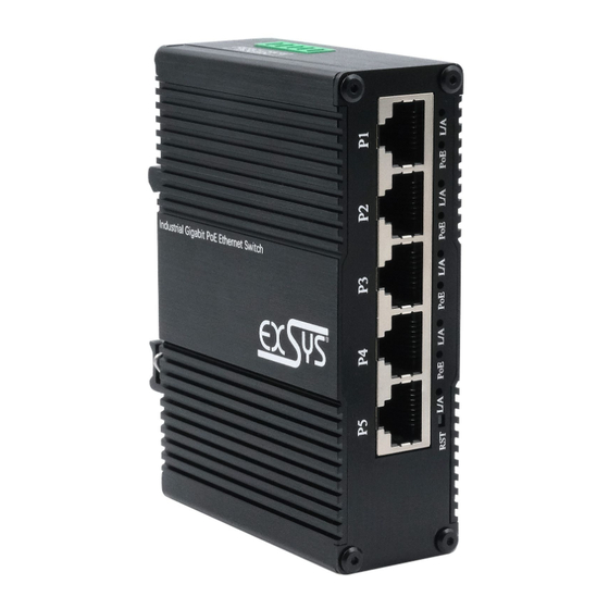
AUFBAU
Power LED
5x RJ45
Gigabit PoE
BESCHREIBUNG & TECHNISCHE DATEN
Der kompakte industrietaugliche 5-Port Gigabit Web-Managed PoE-Switch EX-62030MPoE
bietet trotz seiner geringen Aussenmaße volle Gigabit Leistung an allen Ports. An vier der fünf
RJ45-Ports stehen jeweils bis zu 30W für den Anschluss von PoE Powered Devices (PD) wie
z.B. IP-Kameras oder IP-Telefone zur Verfügung. Die benutzerfreundliche Web-basierte
Management-Benutzeroberfläche des EX-62030MPoE ermöglicht eine schnelle und bequeme
Einrichtung, Konfiguration und Verwaltung, inklusive Konfigurationssicherungen und Firmware-
Upgrades. Dank dem robusten Metallgehäuse und dem erweiterten Betriebstemperaturbereich
von -40°C bis 80°C ist er für eine Vielzahl von Anwendungen auch in rauen Umgebungen
geeignet. Die Stromversorgung erfolgt über den Terminal Block (12-48VDC) und kann zur
Verminderungen von Betriebsausfällen auch redundant erfolgen. Im Lieferumfang ist ein DIN-
Rail Kit (vormontiert) und ein Wandmontagebügel enthalten.
Kompatibilität:
Gigabit Ethernet 10/100/1000Base-T
PoE:
IEEE 802.3af/at (PoE+), Mode/Alternative B
Betriebssysteme:
Alle Betriebssysteme
Anschlüsse:
5x RJ45-Buchse, 1x SFP-Slot, 1x Terminal Block 12-48VDC
Lieferumfang:
EX-62030MPoE, DIN-Rail Kit, Wandmontagehalterung,
Anleitung
ACHTUNG!
Bei
geerdetem
Minuspol
unbedingt den Technischen Hinweis auf Seite 3
beachten.
1
12-48V T-Block für optional
erhältliches Netzteil
Status LEDs
der
Stromversorgung

Verwandte Anleitungen für Exsys EX-62030MPOE


Inhaltszusammenfassung für Exsys EX-62030MPOE
- Seite 1 PoE: IEEE 802.3af/at (PoE+), Mode/Alternative B Betriebssysteme: Alle Betriebssysteme Install the EX-62030MPoE on a mounting rail using the DIN-Rail kit. Anschlüsse: 5x RJ45-Buchse, 1x SFP-Slot, 1x Terminal Block 12-48VDC Connect your network devices to the switch using a network cable.
- Seite 2 IEEE 802.3af/at (PoE+), Mode/Alternative B Operating System: All operating systems Installieren Sie den EX-62030MPoE mit dem DIN-Rail Kit auf eine Tragschiene. Connectors: 5x RJ45-Port, 1x SFP slot, 1x Terminal Block 12-48VDC Verbinden Sie Ihre Netzwerkgeräte über ein Netzwerkkabel mit dem Switch.