Grundig CD 3000 Serviceanleitung
Inhaltsverzeichnis
Quicklinks
GRUnDIG
GRUnDIG
@
Inhalt
Sicherheitshinweise
Allgemeine Hinweise
MOS-Hinweise
AusbauhinweiSe
Abgleich
Oszillogramme
Schaltplan
Blockschaltbild
Druckplatten
Flußdagramm
Abkürzungen der
CD-Technik
Blockschaltbild
NF-Gewinnung
Prinzipschaltung
Servoregelung
TeChnische
Daten
SERVICE
MANUAL
@
Contents
Safey instructions
General
notes
MOS-Handling
instructions
Disassembling
instructions
Alignment
Oscillogrammes
Circuit diagram
Block diagram
Component layout
Flowchart
Abbreviations
CD-
technology
Block diagram
Blockdiagram
Servo
Circuit
Technical
data
O
Btx * 32700 #
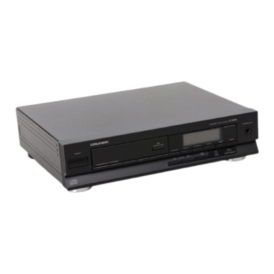
CD 3000
DIGITAL
COM'*CT
PLAYER
AUDIO
Seite/Page
2-5
9-
10
11-12
13 _ 14
15-24
25 - 26
27 - 28
29
30
31
32
33
Inhaltsverzeichnis

Verwandte Anleitungen für Grundig CD 3000


Inhaltszusammenfassung für Grundig CD 3000
- Seite 1 GRUnDIG SERVICE MANUAL Btx * 32700 # CD 3000 DIGITAL AUDIO GRUnDIG COM'*CT PLAYER Contents Inhalt Seite/Page Safey instructions Sicherheitshinweise General notes Allgemeine Hinweise MOS-Handling MOS-Hinweise instructions Disassembling AusbauhinweiSe instructions 11-12 Alignment Abgleich 13 _ 14 Oscillogrammes Oszillogramme 15-24 Circuit diagram...
-
Seite 2: Laser Product
Klasse Class Classe Classe Clase Ungefährlich für Not dangerous to the hu- Non daogereux pour l'oeil Non pericolosa per l'occhio Inofensivo para el Ojo hu- menschliche Auge man eye with a radiation humain 'durant un temps umano con tempi di esposi- mano con tiempos de ra- Bestrahlungszeiten bis zu... -
Seite 3: Safety Requirements
Sicherheitsvorschriften / Safety requirements / Prescrizioni de sicurezza / Prescriptions Nota: Negli apparecchi Observaci6n: En aparatos Observations: L'isolation Comment: On product de sécurité / Prescripciones de seguridad Anmerkung: Bei Geräten delta classe II, Che per de Ia clase de protecciån II, des appareils de la classe conforming to the Safety der Schutzklasse... - Seite 4 Saldatura di un CHIP Soldadura de CHIP's Soldering CHIP Soudure des compo- Einlöten von CHIP Techica CHIP Técnica de CHIP CHIP Technik CHIP Technolo- Technologie sants CMS Bauteilen components 3. LimpiareI punto de sol- 3. Pulire il punto dai residui 3.
- Seite 5 DISASSEMBLY INSTRUCTION AUSBAUHINWEISE Removal of upper part of the casing (Fig. I) Abnehmen des Gehäuseoberteils (Abb. I) Précautions å pren- Handling of MOS Impiego dei compo- Tratamiento Behandlung dre pour Ia manipu• nenu Unscrew three screws a (TORX 10) on the backside - Bauelemen- Chip Components componentes...
- Seite 6 Servicestellung des CDM-Laufwerkes Serviceposition of CDM-Drive NehmenSie die Schubladenblende ab. (Abb. 4) Remove the tray front part (Fig. 4) Lösen SiediedreiSchrauben ( c)aufderBedien- u ndDisplayein- Unscrew thethreescrews(c) ontheuppersideofthedisplayand heit-Oberseite (Abb. 1). control unit. (Fig. I) NehmenSiedie Bedien-und Displayeinheit n achvorneab. Remove the display unit to the front side.
- Seite 7 SERViCEROUTlNE SERVICELOOP Die Serviceschleife ist zur Fehlersuche gedacht Theserviceloop is incorporatedfor faultfinding. Aufrufen der Serviceroutinen Starting the Service Loop Schaften Sie das Gerät aus. Switch the unit off. 2. Drocken SiedieTasten"Track+"und"Track gléichzeitig u nd schalten Sie das Gerät ein. 2. TheServiceLoopis startedby depressingthe buttonsTRACK+ and TRACK •...
- Seite 8 Preparations for alignment Vorbereitungen zum Abgleich 4. Plattentellermotor-Steuersignale/TurntabIe control signals Stellen Sie sicher, daB das Objektiv des optischen Abtastsystems Ensure that the lens in the optical scanning system and the test und die verwendeten CD-Testplatten trei von Staub, Verschmut- CD to be used is free from dust, dirt and finger marks: On no ignal BetriebsarVMode TestpunkVTestpoint...
- Seite 9 NETZTEIL POWER SUPPLY 3112 348 31372 Display Illumination Muting Ein/Aus Mute On/Off 16-2 NETZ 220 v I"402 INAW? 2?ø3 4?øu N4Ød2 3783 2713 4?øu "Augenkurve"/ Pin 32 Dec Oder SAA7310 Eyepattern Pin 32 Decoder SAA7310 271ø ucrges 6585 6583 :N402 Beientsprechender E lnstellungdesOszilloskopes (Time:O,5ms/cm;...
- Seite 10 — — FOKUSSIEROG 1 FOCALIZZAZTE FOC - ITRACKING IFAD - INSEGur&NTO TRACC SEGUIMIENTO OE PISTA L 701 1 OUH LASER -DIODEN-BAUST LASER DIODE MODU-E MÜJLO 01001 LASER FOTODIODEN-BAUST PHOTODIOE MODU-E MODULO DIODI FOTOSENSIBILI MOW-O FOTODIODOS Plattentellermotor Discmotor...
-
Seite 11: Servo Part
SERVOTEIL SERVO PART zur Fokusspule AbtastsignaI-Aufbereitung und Fokusregelung Fokusoffset-EinsteIIung zum Bedien- und Anzeigeteil zum Schubladenmotor Scanning signal processing and focus control Focusoffset-Adjustment to Focuscoil to Control- and Display-Unit to Traymotor 11-13 3-le 13-2 15-1 sseg 3569 Testpunkte Laserstrom- 6513 Einstellung 3621 Testpoints Lasercurrent- BCSO... - Seite 12 DECODERTEIL DECODING PART 1"148 Stummschaltung bei Ein/Aus Muting Power In/Off ecsgs HZ4B2 3912 3848 269' 381t 6S61 3747 3613 Deemphasis 3679 LINKS BC818 2633 NF links Cir{chbuchse DICIUL 3833 CUTPUT n Chg sdcket sons NIERPOurm CIRCUIT tars CREF PLEXER N.E4sse 2671 Decoder 12 a...
-
Seite 13: Saa 7310 Innenbeschaltung
Decoder SAA 7310 Innenbeschaltung od. ext. Vt an SAA720 Ivan 470n ODATA XTALI (vom T 24 MSC Mobr- AO.-.A7 an øxt«nes 16K4-DRAM DO...D4 Mast•- Timng- PROCESSOR DAAB Ent«p Flag. CLAB WSAB SAA7Z ponc (yob) Gengata SAA 7310 Pinning —J index corner TEST3 E FAB... -
Seite 14: Kopfhörer Headphones
BEDIEN- KONTROLLEINHEIT CONTROL DISPLAY UNIT Kopfhörer Headphones zur Hauptplatine to Main p.c.b. r— 3908 egae r. se»... - Seite 15 BEDIEN- UND KONTROLLEINHEIT Kennzeichnung der Chip-Transistoren CONTROL AND DISPLAY UNIT Coding of Chip Transistors OBEN VIEW DE HAUT VISTA VISTO DESDE ARRIBA IS14 3909 A GPIUS21X 1513 BCU8B ecgg 30-1 ! IR GE- 6F- BC818 G2- BF550 BC848 COUI 30-2 BC858 30-6 123456?89...
-
Seite 16: Hauptplatine
BLOCKSCHÅLTBiLD BLOCKDIAGRAM HAUPTPLATINE LASERABTAST-EINHEIT LASER UNIT SERVO DECODER DECODER TIEFPASS LOWPASS DEEM 01-4 KOPFHÖRER-BUCHSE SAA72m PHOTO TDA 1543 HEADPHONE SOCKET FILTER LEFr WSAB LOOPFÜER NF-AUSGANG EFAB CURRENT SOURCE LINE OUT FOCUS OFFSET MUTE ATSB FOCUS ORD.'E SWITCH RADA DAVE MUTING EIN/AUS MUTING POWER... - Seite 17 START POWER ON POWER OFF. SERVICE- POWER ROUTINE EINLEITEN LAMPE DISPLAY ANZEIGE TEST DISC 5 EINLEGEN KI. Sl. TRAFO. SPANNUNG SERVICEPOSITION SPANNG. +5V, IIC-BUS Dtsc EINLEGEN ANWÅHLEN +15, -15. +10. -5, -10 SIGNALE. OSC. KBSC SCHUBLADEN. GESCHWINDIG. BEWEGUNG KEIT DISC 0K SCHUBL.
-
Seite 18: Blockschaltbild
BLOCKSCHALTBILD ABKÜRZUNGEN DER CD-TECHNIK ABBREVIATIONS OFCD-TECHNOLOGY BLOCK DIAGRAM Autom.Gain Co;trol Autom. Verstårkungsregelung NF•Gewinnung Absenkung des NF-PegeIs im SEARCH-Betrieb Attenuation of Audio level in Cueing position Decoding ATSB Equalizer Referenzeingang Equalizer reference current input VerstärkungsregeIungs-Referenzeingang DC and LF control reference input Kontrollbits für Radialservo Control... - Seite 19 Prinzipschaitung der Servoregelung Technical data Technische Daten Ausgangsspannungen AF output voltage Festpegelausgang Fixed output level Amplitudenlinearität Amplitude linearity 20 Hz - 20 kHz Festpegelausgang Fixed voltage output Laser Signalprozessor TDA8808 Phasendifferenz zwischen éen Kanälen Phase difference between the channels laufwerk Festpegelausgang asersup- Fixed voltage output...
-
Seite 20: Exploded View
75987-528.14 75987-528.22 75987-528.24 (243) (212) (209) CD 3000 GRunDIG 75987-528.21 75987-528.40 75987-528.23 75987-52B.17 (215) (214) (216) (245) Explolsionsdarstellung Exploded view... -
Seite 21: Ersatzteilliste
Ersatzteilliste GRUnDIG List of spare parts PART NUMBE DESCRIPTION DESCRIPTION pos. POS. NUMBER Btx *32700# 11 / 89 CD 3000 OUARZ 11,2896 MHZ 01.11502 8382-439-011 SI-KERKO.(A) 3300PF C 2500 8660-197-042 QUARZ 4 MHZ QU1503 75986-200.89 ELKO 1000M c 2711 75987-528.16...