FS S5440L-48M Schnellstartanleitung
Unternehmens-switch
Inhaltsverzeichnis
Verfügbare Sprachen
Verfügbare Sprachen
Quicklinks
1
2
3
4
5
6
7
8
9
10
11
12
13
14
15
16
17
18
19
20
21
22
23
24
25
26
27
28
29
30
31
32
33
34
35
36
37
38
39
40
41
42
43
44
45
46
47
48
49
50
51
52
53
54
S5440L-48M
ENTERPRISE SWITCH
UNTERNEHMENS-SWITCH
COMMUTATEUR D'ENTREPRISE
エンタープライズスイッチ
Quick Start Guide
V1.0
Quick Start Anleitung
Guide de Démarrage Rapide
クイックスタートガイド
Inhaltsverzeichnis

Verwandte Anleitungen für FS S5440L-48M


Inhaltszusammenfassung für FS S5440L-48M
- Seite 1 S5440L-48M ENTERPRISE SWITCH UNTERNEHMENS-SWITCH COMMUTATEUR D'ENTREPRISE エンタープライズスイッチ Quick Start Guide V1.0 Quick Start Anleitung Guide de Démarrage Rapide クイックスタートガイド...
-
Seite 2: Accessories
Introduction Thank you for choosing the Enterprise Switch. This guide is designed to familiarize you with the layout of the switch and describes how to deploy it in your network. S5440L-48M Accessories Power Cord x1 Console Cable x1 Network Cable x1... -
Seite 3: Hardware Overview
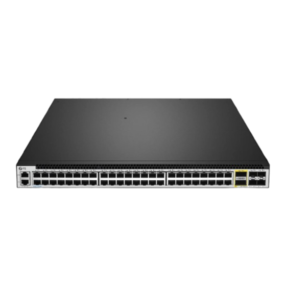
Hardware Overview Front Panel Ports RJ45 SFP28 QSFP+ Ports Description SFP28 SFP28 ports for 10/25 Gbps connection QSFP+ QSFP+ ports for 40 Gbps connection. Support 4×10 Gbps breakout RJ45 RJ45 ports for 100 Mbps/1/2.5 Gbps Ethernet connection An RJ45 console port for serial management An Ethernet management port Front Panel LEDs SFP28... - Seite 4 State Description LEDs Solid Blue The ID indication function is enabled. The ID indication function is disabled. Solid Green The port is connected. MGMT Blinking Amber The port is receiving or transmitting data. The port is not connected. Solid Green The system is running normally.
-
Seite 5: Installation Requirements
Installation Requirements Before the installation, please make sure that you have prepared the following: Standard-sized, 19-inch-wide rack with a minimum of 1U height available. Category 5e or higher RJ45 Ethernet cables, and ber optical cables. M6 screws and cage nuts. Phillips screwdriver. -
Seite 6: Mounting The Switch
Mounting the Switch Desk Mounting 1. Attach four rubber pads to the switch bottom. 2. Place the switch on a stable desk. M od ul e1 Rack Mounting 1. Secure the mounting brackets to the two sides of the switch with twelve M4 screws. - Seite 7 2. Attach the switch to the rack using self-provided M6 screws and cage nuts. Grounding the Switch M od ul e2 PW R1 PW R2 1. Connect one end of the grounding cable to a proper earth ground, such as the rack in which the switch is mounted.
- Seite 8 Connecting the SFP28 Ports 1. Plug the compatible SFP28 transceiver into the SFP28 port. 2. Connect a ber optic cable to the transceiver, then connect the other end of the cable to another ber device. Connecting the QSFP+ Ports 1. Plug the compatible QSFP+ transceiver into the QSFP port. 2.
- Seite 9 Connecting the RJ45 Ports 1. Connect an Ethernet cable to the RJ45 port of a computer, printer, network storage, or other network devices. 2. Connect the other end of the Ethernet cable to the RJ45 port of the switch. Connecting the ETH Port M od ul e1 1.
-
Seite 10: Connecting The Power
Connecting the Console Port 1. Insert the RJ45 connector of the console cable into the console port on the front of the switch. 2. Connect the other end of the console cable to the RS-232 serial port on the computer. Connecting the Power M od ul e2 PW R1... - Seite 11 Con guring the Switch Con guring the Switch Using the Web-Based Interface Step 1: Connect the computer to any Ethernet port of the switch using the network cable. Step 2: Set the IP address of the computer to 192.168.1.x ("x" is any number from 2 to 254). I nte rn et Proto c o l Ve rsi on 4 ( TC P/ I P v 4 ) P rop e r t i e s General Yo u c a n g e t I P s e t t i n g s a s s i g n e d a u t o m a t i c a l l y i f y o u r n e t w o r k...
- Seite 12 Con guring the Switch Using the Console Port Step 1: Connect a computer to the switch's console port using the supplied console cable. Step 2: Start the terminal simulation software such as HyperTerminal on the computer. Step 3: Set the parameters of the HyperTerminal: Baud rate to 115200, Data bits to 8, Parity to None, and Stop bits to 1.
- Seite 13 Troubleshooting Con guration Terminal Shows No Display or Garbled Texts Check the power supply status. Check whether the console cable is undamaged and securely connected. Check whether the connected console port is consistent with the console port con gured in HyperTerminal. Check terminal settings (baud rate to 115200 , data bits to 8, no parity, stop bit to 1).
-
Seite 14: Product Warranty
Product Warranty FS ensures our customers that for any damage or faulty items due to our workmanship, we will o er a free return within 30 days from the day you receive your goods. This excludes any custom-made items or tailored solutions. -
Seite 15: Einführung
Einführung Vielen Dank, dass Sie sich für den Unternehmens-Switch entschieden haben. In dieser Anleitung werden Sie mit dem Aufbau des Switches vertraut gemacht und erfahren, wie Sie ihn in Ihrem Netzwerk einsetzen können. S5440L-48M Zubehör Netzkabel x1 Konsolenkabel x1 Netzwerkkabel x1... -
Seite 16: Hardware-Übersicht
Hardware-Übersicht Ports an der Vorderseite RJ45 SFP28 QSFP+ Ports Beschreibung SFP28 SFP28-Ports für 10/25 GB/s Verbindungen QSFP+ QSFP+-Ports für 40 GB/s-Verbindungen. Unterstützt 4×10 GB/s Breakout RJ45 RJ45-Ports für 100 MB/s /1/2.5 GB/s Ethernet-Verbindungen Ein RJ45-Konsolenport für serielle Verwaltung Ein Ethernet-Verwaltungsport LEDs an der Vorderseite SFP28 MGMT... -
Seite 17: Beschreibung
LEDs Status Beschreibung leuchtet blau Die ID-Identi kationsfunktion ist aktiviert Die ID-Identi kationsfunktion ist deaktiviert leuchtet grün Der Port ist verbunden blinkt orange Der Port empfängt oder überträgt Daten MGMT Der Port ist nicht verbunden leuchtet grün Das System läuft normal Das System hat einen Alarm oder leuchtet orange Fehlerzustand ausgelöst... -
Seite 18: Aufstellungsort
Installationsanforderungen Bevor Sie mit der Installation beginnen, stellen Sie sicher, dass die folgenden Gegenstände bereitliegen: 19"-Standard-Rack mit einer Mindesthöhe von 1 HE RJ-45 Ethernet-Kabel der Kategorie 5e oder höher, und Glasfaserkabel M6-Schrauben und -Kä gmuttern Kreuzschlitzschraubendreher Antistatik-Armband, -Handschuhe oder -Kleidung Kabelbinder, Marker, Cuttermesser Aufstellungsort: Stellen Sie sicher, dass sich die Betriebstemperatur zwischen 0°C und 45°C be ndet. -
Seite 19: Montage Der Switches
Montage der Switches Tischmontage 1. Befestigen Sie vier Gummipads an der Unterseite des Switches. 2. Platzieren Sie den Switch auf einem stabilen Tisch. Rackmontage M od ul e1 1. Befestigen Sie die Montagehalterungen mit acht M4-Schrauben an den Seiten des Switches. -
Seite 20: Erdung Des Switches
2. Befestigen Sie den Switch mit M6-Schrauben und -Kä gmuttern aus eigenem Bestand am Rack. Erdung des Switches M od ul e2 PW R1 PW R2 M od ul e1 1. Schließen Sie ein Ende des Erdungskabels an eine geeignete Erdung an, z. B. an das Rack, in dem der Switch montiert ist. -
Seite 21: Verbinden Der Sfp28-Ports
Verbinden der SFP28-Ports 1. Schließen Sie einen kompatiblen SFP28-Transceiver an dem SFP28-Port des Switches 2. Schließen Sie ein Ende eines Glasfaserkabels an den Transceiver an und das andere Ende des Kabels an ein anderes Glasfasergerät. Verbinden der QSFP+-Ports M od ul e2 PW R1 PW R2 1. - Seite 22 Verbinden des RJ45-Ports 1. Schließen Sie ein Ethernetkabel an den RJ45-Port eines Computers, Druckers, Netzwerkspeichers oder anderen Netzwerkgeräts an. 2. Schließen Sie das andere Ende des Ethernetkabels an den RJ45-Port des Switches an. Verbinden des ETH-Ports M od ul e1 1.
-
Seite 23: Anschließen Der Stromversorgung
Verbinden des Konsolenports 1. Schließen Sie das RJ45-Ende des Konsolenkabels an den Konsolenport auf der Vorderseite des Switches an. 2. Schließen Sie das andere Ende des Konsolenkabels an den RS-232-Serienport eines Computers an. Anschließen der Stromversorgung M od ul e2 PW R1 PW R2 1. -
Seite 24: Kon Guration Des Switches Mithilfe Der Webbasierten Schnittstelle
Kon guration des Switches Kon guration des Switches mithilfe der webbasierten Schnittstelle Schritt 1: Schließen Sie mit dem Netzwerkkabel einen Computer an den Ethernet-Port des Switches an. Schritt 2: Legen Sie 192.168.1.X ("X" ist eine beliebige Zahl zwischen 2 und 254) als die IP-Adresse des Computers fest. -
Seite 25: Kon Guration Des Switches Mit Dem Konsolenport
Kon guration des Switches mit dem Konsolenport Schritt 1: Schließen Sie mit dem Konsolenkabel Ihren Computer an den Konsolenport des Switches an. Schritt 2: Starten Sie eine Terminalsimulationssoftware wie beispielsweise HyperTerminal auf dem Computer. Schritt 3: Setzen Sie die folgenden Parameter in HyperTerminal: Baudrate auf 115200, Datenbits auf 8, Parität auf keine und Stopbits auf 1. - Seite 26 Fehlerbehebung Kon gurationsterminal zeigt nichts an oder gibt keinen sinnvollen Text aus Überprüfen Sie den Status der Stromversorgung. Überprüfen Sie das Konsolenkabel auf Schäden oder wackelige Verbindung. Überprüfen Sie, ob der angeschlossene Konsolenanschluss mit dem in HyperTerminal kon gurierten Konsolenanschluss übereinstimmt. Überprüfen Sie die Terminaleinstellungen (Baudrate 115200, Datenbits 8, keine Parität, Stoppbits 1, keine Flusskontrolle, und Terminalemulation VT100).
-
Seite 27: Produktgarantie
Produktgarantie FS garantiert seinen Kunden bei allen Schäden oder Fehlern, die auf FS zurückzuführen sind, eine kostenlose Rückgabe innerhalb von 30 Tagen nach Erhalt der Ware. Ausgenommen sind Sonderanfertigungen oder maßgeschneiderte Lösungen. Garantie: Für dieses Produkt gilt eine eingeschränkte Garantie über 5 Jahre auf Material- und Verarbeitungsfehler. - Seite 28 Introduction Merci d'avoir choisi ce commutateur d'entreprise. Ce guide a pour but de vous familiariser avec la con guration du commutateur et décrit comment procéder à son installation. S5440L-48M Accessoires Câble d'alimentation x1 Câble console x1 Câble réseau x1 Câble de mise à la terre x1...
-
Seite 29: Présentation Du Matériel
Présentation du Matériel Ports du Panneau Frontal RJ45 SFP28 QSFP+ Ports Description SFP28 Ports SFP28 pour une connexion 10/25 Gbps. Ports QSFP+ pour une connexion 40 Gbps. Prise en charge de 4×10 QSFP+ Gbps breakout. RJ45 Ports RJ45 pour une connexion Ethernet 100 Mbps/1/2,5 Gbps. Port console RJ45 pour la gestion série. - Seite 30 État Description Bleu La fonction d'indication d'ID est activée. Éteint La fonction d'indication d'ID est désactivée. Le port est connecté. Vert MGMT Jaune clignotant Le port reçoit ou transmet des données. Éteint Le port n'est pas connecté. Vert Le système fonctionne normalement. Le système a déclenché...
-
Seite 31: Conditions Requises Pour L'installation
Conditions Requises pour l'Installation Avant l'installation, veuillez vous assurer que vous disposez des éléments suivants : Rack standard de 19 pouces de large avec une hauteur minimale de 1U disponible. Câbles Ethernet RJ45 de catégorie 5e ou supérieure et câbles à bre optique. Vis M6 et écrous cage. -
Seite 32: Installation En Rack
Installation du Commutateur Installation sur un bureau 1. Fixez quatre pads en caoutchouc à la base du commutateur. 2. Placez le commutateur sur un bureau ou une surface plane stable. M od ul e1 Installation en rack 1. Fixez les supports de montage aux deux côtés du commutateur à l'aide de douze vis M4. - Seite 33 2. Fixez le commutateur au rack à l'aide des vis M6 et des écrous cage fournis. Mise à la Terre du Commutateur M od ul e2 PW R1 PW R2 1. Connectez une extrémité du câble de mise à la terre à un point de mise à la terre approprié, tel que le rack dans lequel le commutateur est installé.
- Seite 34 Connexion des Ports SFP28 1. Branchez l'émetteur-récepteur SFP28 compatible dans le port SFP28. 2. Connectez un câble à bre optique à l'émetteur-récepteur, puis connectez l'autre extrémité du câble à un autre appareil à bre optique. Connexion des Ports QSFP+ M od ul e1 1.
- Seite 35 Connexion des Ports RJ45 1. Connectez un câble Ethernet au port RJ45 d'un ordinateur, d'une imprimante, d'un périphérique de stockage réseau ou d'autres périphériques réseau. 2. Connectez l'autre extrémité du câble Ethernet au port RJ45 du commutateur. Connexion du Port ETH M od ul e1 M od ul e2 PW R1...
-
Seite 36: Branchement De L'alimentation
Connexion du Port Console 1. Insérez le connecteur RJ45 du câble console dans le port console situé sur la facefrontale du commutateur. 2. Connectez l'autre extrémité du câble console au port série RS-232 de l'ordinateur. Branchement de l'Alimentation M od ul e2 PW R1 PW R2 1. - Seite 37 Con guration du Commutateur Con guration du commutateur à l'aide de l'interface Web Étape 1 : Connectez l'ordinateur à n'importe quel port Ethernet du commutateur à l'aide du câble réseau. Étape 2 : Dé nissez l'adresse IP de l'ordinateur sur 192.168.1.x ( x étant un nombre compris entre 2 et 254).
- Seite 38 Con guration du commutateur à l'aide du port console Étape 1 : Connectez un ordinateur au port console du commutateur à l'aide du câble console fourni. Étape 2 : Lancez le logiciel HyperTerminal sur l'ordinateur. Étape 3 : Dé nissez les paramètres de HyperTerminal : Baud rate à 115200, Data bits à 8, Parity à...
- Seite 39 Dépannage L'écran du terminal de con guration n'a che rien ou a che des caractères illisibles Véri ez l'état de l'alimentation électrique. Véri ez que le câble de la console n'est pas endommagé et qu'il est correctement connecté. Véri ez que le port de la console connecté correspond au port de la console con guré dans HyperTerminal.
-
Seite 40: Garantie Du Produit
Garantie du Produit FS garantit à ses clients quetout article endommagé ou défectueux en raison de sa fabrication pourra être retourné gratuitement dans les 30 jours suivant la date de réception. Cette garantie exclut les articles sur mesure ou les solutions personnalisées. - Seite 41 はじめに エンタープライズスイッチをお買い上げいただき、ありがとうございます。本ガイドは、 スイッチのレイアウトを理解し、ネットワークに導入する方法を説明するためのものです。 S5440L-48M 付属品 電源コード x� コンソールケーブル x� ネッ トワークケーブル x� 接地ケーブル x� M�ネジ x�� 取り付けブラケッ ト x� ゴムパッ ド x� 注: 付属品はイラストと異なる場合がありますので、あらかじめご了承ください。...
-
Seite 42: フロントパネルLed
ハードウェアの概要 フロントパネルポート RJ�� SFP�� QSFP+ ポート 説明 SFP�� ��/��Gbps接続用SFP��ポート QSFP+ ��Gbps接続用QSFP+ポート。�×��Gbpsブレークアウト対応。 ���Mbps/�/�.�Gbpsイーサネット接続用RJ��ポート RJ�� シリアル管理用RJ��コンソールポート イーサネット管理ポート フロントパネルLED SFP�� MGMT RJ�� QSFP+... - Seite 43 状態 説明 青の点灯 ID表示機能が有効になっています。 ID表示機能は無効です。 オフ 緑の点灯 ポートは接続されています。 ポートがデータを受信または送信しています。 MGMT 琥珀色の点滅 オフ ポートは接続されていません。 緑の点灯 システムは正常に稼動しています。 システムがアラームまたはエラー状態を引き起こ 琥珀色の点灯 しました。 システムに電源が供給されないか、動作しないか、 オフ または機能が異常になっています。 緑の点灯 ポートはリンクされています。 緑の点滅 ポートがパケットを受信または送信しています。 オフ ポートはリンクされていません。 緑の点灯 ポートは�.�Gbpsでリンクされています。 ポートは�.�Gbpsでパケットを受信または送信して 緑の点滅 います。 RJ�� 琥珀色の点灯 ポートは���Mbps/�Gbpsでリンクされています。 ポートは���Mbps/�Gbpsでパケットを受信または 琥珀色の点滅 送信しています。 ポートはリンクされていません。 オフ 緑...
- Seite 44 設置の条件 取り付けの前に、以下の物が準備されていることを確認してください: 標準サイズの��インチ幅ラックで、最低�Uの高さから利用可能です。 カテゴリー�e以上のRJ��イーサネットケーブル、光ファイバーケーブル。 M�ネジとケージナット。 プラスドライバー。 ESDブレスレット、ESD手袋、ESDウェア。 結束バンド、マーカー、カッターナイフ。 設置環境 使用温度が�℃~��℃に保たれていることを確認してください。 使用湿度が��%~��%に保たれていることを確認してください。 スイッチの周囲に十分な空気の流れがあるように、設置場所の換気を確保してく ださい。 設置場所にほこり、水漏れ、水滴、激しい結露、湿気がないことを確認してください。 ラックが適切に接地されていることを確認してください。 放熱やメンテナンスを容易にするため壁際への設置は避け、四方に十分なスペースを 確保してください。...
- Seite 45 スイッチの取り付け デスクへの取り付け �. スイッチの底に�つのゴムパッドを取り付けます。 �. スイッチを安定したデスクの上に置きます。 ラックへの取り付け M od ul e1 �. 取り付けブラケットをスイッチの両側面にM�ネジ��本で固定します。...
- Seite 46 �. 自分で用意したM�ネジとケージナットを使用して、スイッチをラックに取り付けます。 スイッチの接地 M od ul e2 PW R1 PW R2 �. 接地ケーブルの一端を、スイッチが取付けられているラック等の適切な場所に接続しま す。 �. 接地ケーブルのもう一方の端を、ワッシャーとネジでスイッチのバックパネルの接地ポ イントに固定します。...
- Seite 47 SFP��ポートへの接続 �. 互換性のあるSFP��トランシーバーをSFP��ポートに差し込みます。 �. 光ファイバーケーブルの一端をトランシーバーに接続し、もう一端を別のファイバー機 器に接続します。 QSFP+ポートへの接続 �. 互換性のあるQSFP+トランシーバーをQSFPポートに差し込みます。 �. 光ファイバーケーブルをトランシーバーに接続し、ケーブルのもう一方の端を別の光フ ァイバー機器に接続します。...
- Seite 48 RJ��ポートへの接続 �. イーサネットケーブルをコンピューター、プリンター、ネットワークストレージ、その 他のネットワーク機器のRJ��ポートに接続します。 �. イーサネットケーブルのもう一方の端を、スイッチのRJ��ポートに接続します。 ETHポートへの接続 M o d u le 1 �. 付属のネットワークケーブルの一端をコンピューターに接続します。 �. ケーブルのもう一方の端をスイッチ前面のETHポートに接続します。...
- Seite 49 コンソールポートへの接続 �. コンソールケーブルのRJ��コネクターをスイッチ前面のコンソールポートに挿入します。 �. コンソールケーブルのもう一方の端をコンピューターのRS-���シリアルポートに接続し ます。 電源接続 M od ul e2 PW R1 PW R2 �. AC電源コードをスイッチの背面にある電源ポートに差し込みます。 �. 電源コードのもう一方の端をAC電源に接続します。...
- Seite 50 スイッチの設定 ウェブベースのインターフェイスを使用したスイッチの設定 Step �: コンピューターとスイッチのイーサネットポートをネットワークケーブルで接続 します。 Step �: コンピューターのIPアドレスを���.���.�.x(「x 」は�から���までの任意の数字) に設定します。 I nte rn et Proto c o l Ve rsi on 4 ( TC P/ I P v 4 ) P rop e r t i e s General Yo u c a n g e t I P s e t t i n g s a s s i g n e d a u t o m a t i c a l l y i f y o u r n e t w o r k s u p p o r t s t h i s c a p a b i l i t y .
- Seite 51 コンソールポートを使ったスイッチの設定 Step �: 付属のコンソールケーブルを使用して、コンピューターをスイッチのコンソール ポートに接続します。 Step �: コンピューター上でHyperTerminalなどの端末シミュレーションソフトを起動し ます。 Step �: ハイパーターミナルの各パラメーターを設定します: ボーレートは������、デ ータビットは�、パリティはなし、ストップビットは�。 Quick Connect Serial Protocol: The port may be manually entered or selected from the list. COM5 USB Serial Port Port: Flow Control 115200 Baud rate: DTR/DSR Data bits: RTS/CTS None...
- Seite 52 問題解決 設定端末が表示されない、または文字化けする場合 電源の供給状態を確認します。 コンソールケーブルが損傷していないか、確実に接続されているか確認します。 接続されているコンソールポートが、ハイパーターミナルで設定されているコンソー ルポートと一致しているか確認します。 端末設定を確認します(ボーレートは������、データビットは�、パリティなし、スト ップビットは�)。 新しく挿入した拡張モジュールの電源が入らない場合 モジュールが正しく挿入されているか確認します。 光ポートがリンクしない場合 ファイバーのTXとRXの接続が正しいか確認します。 相互接続されている光モジュールが同じ波長を使用しているか確認します。 実際のリンク距離が光モジュールの最大サポート距離を越えていないか確認します。 両端のポート速度が一致しているか確認します。 ファイバーの種類が伝送条件を満たしているか確認します。 マルチレートポートのポートレートモードが正しく設定されているか確認します。 上記の問題が解決しない場合は、テクニカルサポートにお問い合わせください。...
- Seite 53 製品保証 FSは、カスタム製品又はカスタムソリューションを除き、当社の過失による製品の破損 や不良品があった場合、お客様が製品を受け取った日から��日以内に無料で返品をする ことを保証します。 保証: この製品は、材料または製造上の欠陥に対して�年間の限定保証を提供し ます。保証の詳細については、下記のURLをご参照ください。 https://www.fs.com/jp/policies/warranty.html 返品: 返品を希望される場合、方法については下記のURLをご参照ください。 https://www.fs.com/jp/policies/day_return_policy.html オンラインリソース その他の技術資料については、下記のURLをご参照ください。 https://www.fs.com/jp/technical_documents.html FSアプリをダウンロード QRコードを読み取り、App StoreまたはGoogle PlayストアからFSア プリをダウンロードしてインストールできます。若しくは下記の URLにアクセスしてください。 https://www.fs.com/jp/appdownload.html Q.C. PASSED Copyright © 2025 FS.COM All Rights Reserved.