Werbung
Quicklinks
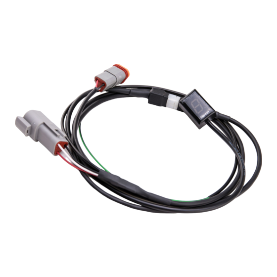
Montageanleitung Ganganzeige Kabelkit GPX S01
Montage
Der Einbau ist mit Grundkenntnissen in Mechanik und Elektrik einfach und
innerhalb kurzer Zeit erledigt. Sollten sie diese Kenntnisse nicht besitzen,
überlassen Sie die Montage einem Fachmann.
Nach dem Auffinden des fahrzeugspezifischen Geschwindigkeitssensors wird
das mitgelieferte Adapterkabel auf die originalen Stecker aufgesteckt.
Die Sensoren sitzen meist auf der Ritzelabdeckung oder sind von oben in das
Getriebe (in Höhe der Getriebeausgangswelle ) geschraubt. Zum testen den
Stecker trennen und das Hinterrad bei eingeschalteter Zündung schnell drehen.
Wird keine Geschwindigkeit angezeigt, ist der richtige Stecker gefunden.
Achten Sie darauf, Kabel nicht direkt in der Nähe von heißen Motor- oder
Auspuffteilen zu montieren/befestigen.
Lokalisieren Sie jetzt das Motorsteuergerät. Es ist die flache Box mit ein oder
zwei größeren Kompaktsteckern. Verbinden Sie dort die Leitung des
Drehzahlsignals mit der schwarz/grünen Leitung der Ganganzeige. Bei den
meisten Motorrädern kann das Drehzahlsignal auch vorne am Cockpit
abgegriffen werden.
YZF-R6
YZF-R1
BT 1100 Bulldog
FZ6/FZS600 Fazer
FZ1/FZS1000 Fazer
XJR 1300
alle anderen Modelle: graue Leitung; es handelt sich um die Leitung des
Schließen Sie jetzt die rote Leitung des Kabelsatzes an +12 Volt an (über
Zündung geschaltet); z.B. die Stromversorgung des Rücklichts.
Kontrollieren Sie jetzt den Anschluss, indem Sie die Ganganzeige aufstecken.
Legen Sie den Leerlauf ein und schalten die Zündung ein. Die Ganganzeige
zählt von 6 auf 1 runter und es blinkt langsam das "L". Starten Sie den Motor;
das "L" muss für einige Sekunden schneller blinken. Wenn "1" langsam blinkt,
legen Sie den ersten Gang ein, kuppeln ein und erhöhen die Drehzahl. Wenn
die "1" schneller blinkt, legen Sie wieder den Leerlauf ein und schalten die
Zündung aus. Ist dieser Test erfolgreich, können Sie die Lernprozedur komplett
durchführen. Verlegen und befestigen Sie alle Leitungen und die Ganganzeige.
Kabel gelb/schwarz an ECU oder Kombiinstrument
ACHTUNG: bei einigen Modellen findet man dort auch
eine schwarz/gelbe-Leitung → nicht verwechseln!
Die richtige (gelb/schwarz) führt von der ECU ins
Cockpit.
Kurbelwellensensors zur ECU/Motorsteuergerät; kann
auch für oben stehende Modelle angewendet werden
Werbung

Inhaltszusammenfassung für Heal-Tech GPX-Y01
- Seite 1 Montageanleitung Ganganzeige Kabelkit GPX S01 Montage Der Einbau ist mit Grundkenntnissen in Mechanik und Elektrik einfach und innerhalb kurzer Zeit erledigt. Sollten sie diese Kenntnisse nicht besitzen, überlassen Sie die Montage einem Fachmann. Nach dem Auffinden des fahrzeugspezifischen Geschwindigkeitssensors wird das mitgelieferte Adapterkabel auf die originalen Stecker aufgesteckt.
-
Seite 2: Montage
Bedienungsanleitung /Montageanleitung Ganganzeige X- Type/GPX Montage Der Einbau ist mit Grundkenntnissen in Mechanik und Elektrik einfach und innerhalb kurzer Zeit erledigt. Sollten Sie diese Kenntnisse nicht besitzen, überlassen Sie die Montage einem Fachmann. 1. Funktionsweise Die X-Type-Reihe ist für den Einsatz an Motorrädern ohne Gangsensor geeignet. - Seite 3 4. Reset Nach dem Einschalten der Zündung muss während dem Hochzählen von 1 auf 6 (wenn im Display 3, 4 oder 5 angezeigt wird), die Spannung unterbrochen werden. Bei vielen Motorrädern kann man dazu den "Killschalter" nutzen. Nach dem Wiedereinschalten muss wieder bei 3, 4 oder 5 die Spannung unterbrochen werden.
- Seite 4 GIpro Bike plug at the wiring harness side 3. a) When using the GPX-Y01 kit: Find the 2-pole natural (or black) color plug of the Crankshaft position sensor (Pickup coil). It has two wires coming from the crankcase: one is Gray, the other is usually Black/Blue - check the colors at both sides of the plug (if in doubt, do a temporary connection e.g.
- Seite 5 b) When using the GPX-Y03 or Y04 kit: Find the 2-pole plug of the AC magneto (Crankshaft position sensor/Pickup coil). It has two wires coming from the crankcase: one is Red, the other is usually White 4. On the wire identified in the previous step, peel off the black sleeve (tape) near the 2-pole plug, leaving about 3 cm (1.2”) of the wire exposed.
-
Seite 6: Installation
X-type Gear Position Indicator with programmable Shift Light and High Speed Warning User’s Guide 1. Foreword Congratulations on your purchase of a GIpro X-type gear position indicator. The GIpro products from HealTech Electronics Ltd. are the most advanced gear position indicators on the market today. This GIpro model will fit all motorcycles and vehicles which have an electronic speedometer (either analogue or digital readout). - Seite 7 4. Setup You need to set up this module after installation. It is recommended to perform the setup procedure with WARM engine. - Raise rear wheel ground using stand. (If you do not have a stand, or your speedometer is driven off the front wheel, set up the unit while riding.
- Seite 8 5. Reset If some gears are not indicated correctly, reset the unit and set it up again. - Have the engine stop switch in OFF position. - Turn the ignition key ON and immediately turn it off while the GIpro display is counting up and is showing “3, or 5”.
-
Seite 9: Warranty
- Select a high gear and raise your speed gradually and slowly to the desired speed. Hold it for a second, then slow down and stop. (You should of course slow down and stop as traffic conditions dictate. The unit will not exit from learning mode until you stop the engine. - Seite 10 Yamaha FZS600 Fazer 1998-2003 S U P P L E M E N T A R Y M A N U A L for GPX-Y01 Remove the seat. Remove the left and right black frame covers from below seat. Lift up or remove the fuel tank.
- Seite 11 Yamaha FZS600 Fazer 1998-2003 Connect GPX red wire to brown wire of rear brakelight switch connector. (brown, 2-pole brown connector at right side) www.healtech-electronics.com PAGE 2/2...
- Seite 12 Yamaha FZS1000 Fazer 2001-2005 S U P P L E M E N T A R Y M A N U A L for GPX-Y01 Remove the seat. Remove the right black frame cover from below seat. Plug GPX connectors in-line with the speed sensor connectors.
- Seite 13 Yamaha FZS1000 Fazer 2001-2005 Connect GPX black/green wire gray wire of crankshaft position sensor connector. (transparent, 2-pole connector in dust boot at right side) Connect GPX red wire to brown wire of rear brakelight switch connector. (brown, 2-pole connector at right side) Typical position for the gear indicator.
- Seite 14 Yamaha TDM850 1996-2001 S U P P L E M E N T A R Y M A N U A L for GPX-Y01 Remove the seat. Lift up or remove the fuel tank. Plug GPX connectors in-line with the speed sensor connectors.
- Seite 15 Yamaha TDM850 1996-2001 Connect GPX red wire to brown wire of rear brakelight switch connector. (transparent, 2-pole connector at right side near fuse box) Typical position for the gear indicator. www.healtech-electronics.com PAGE 2/2...
- Seite 16 Yamaha TDM900 2002-2010 S U P P L E M E N T A R Y M A N U A L for GPX-Y01 Remove the seat. Remove the black covers from fuel tank. Remove the middle fairing at both side.
- Seite 17 Yamaha TDM900 2002-2010 Connect GPX black/green wire orange wire of ignition coil. (ignition coil left side on frame) Connect GPX red wire to brown wire of rear brakelight switch connector. (brown, 2-pole connector at right side) Typical position for the gear indicator.
- Seite 18 Yamaha WR250X 2008-2013 S U P P L E M E N T A R Y M A N U A L for GPX-Y01 Remove the seat. Remove frame covers under seat. Remove the side fairings. Plug GPX connectors in-line with the speed sensor connectors.
- Seite 19 Yamaha WR250X 2008-2013 Connect GPX black/green wire orange wire of ECU/ECM. (black connector, PIN #17, below seat) Connect GPX red wire to brown wire of rear brakelight switch connector. (white, 2-pole connector at left side near frame) Typical position for the gear indicator.
- Seite 20 Yamaha XJ6N 2009-2012 S U P P L E M E N T A R Y M A N U A L for GPX-Y01 Remove the seat. Lift up or remove the fuel tank. Plug GPX connectors in-line with the speed sensor connectors.
- Seite 21 Yamaha XJ6N 2009-2012 Connect GPX red wire to brown wire of rear brakelight switch connector. (white, 2-pole connector in dust boot below fuel tank) Typical position for the gear indicator. www.healtech-electronics.com PAGE 2/2...
- Seite 22 Yamaha XJR1300 2004-2008 S U P P L E M E N T A R Y M A N U A L for GPX-Y01 Remove the seat. Remove the black frame covers below seat. Lift up or remove the fuel tank.
- Seite 23 Yamaha XJR1300 2004-2008 Connect GPX red wire to brown wire of rear brakelight switch connector. (black, 2-pole connector at right side below frame cover) Typical position for the gear indicator. www.healtech-electronics.com PAGE 2/2...
- Seite 24 Yamaha XV1900 Midnight Star 2006-2013 S U P P L E M E N T A R Y M A N U A L for GPX-Y01 Remove the main seat. Lift up or remove the fuel tank. Remove or lift up the ECU/ECM.
- Seite 25 Yamaha XV1900 Midnight Star 2006-2013 Connect GPX black/green wire to gray (light gray) wire of crankshaft position sensor connector. (transparent, 2-pole connector below ECU/ECM) Connect GPX red wire to blue wire of rear light connector. (transparent, 6-pole connector below ECU/ECM) Typical position for the gear indicator.
- Seite 26 Yamaha XVS1100 Drag Star 1999-2006 S U P P L E M E N T A R Y M A N U A L for GPX-Y01 Remove the seats. Remove two chrome frame covers at left side. Lift up or remove the fuel tank.
- Seite 27 Yamaha XVS1100 Drag Star 1999-2006 Connect GPX red wire to switched +12V wire. Typical position for the gear indicator. www.healtech-electronics.com PAGE 2/2...
- Seite 28 Yamaha R1 2002-2003 S U P P L E M E N T A R Y M A N U A L for GPX-Y01 Remove the main seat. Lift up or remove the fuel tank. Plug GPX connectors in-line with the speed sensor connectors.
- Seite 29 Yamaha R1 2002-2003 Connect GPX black/green wire gray wire of crankshaft position sensor connector. (transparent, 2-pole connector at right side) Connect GPX red wire to brown wire of rear brakelight switch connector. (brown, 2-pole connector at right side) Typical position for the gear indicator.
- Seite 30 Yamaha R1 2004-2006 S U P P L E M E N T A R Y M A N U A L for GPX-Y01 Remove the main seat. Remove the black tank covers. Lift up or remove the fuel tank.
- Seite 31 Yamaha R1 2004-2006 Connect GPX black/green wire gray wire of crankshaft position sensor connector. (transparent, 2-pole connector at right side below fuel tank) Connect GPX red wire to brown wire of rear brakelight switch connector. (brown, 2-pole connector at right side below fuel tank) Typical position for the gear indicator.
- Seite 32 Yamaha R1 2007-2008 S U P P L E M E N T A R Y M A N U A L for GPX-Y01 Remove the main seat. Remove the tank cover. Lift up or remove the fuel tank. Plug GPX connectors in-line with the speed sensor connectors.
- Seite 33 Yamaha R1 2007-2008 Connect GPX red wire to brown wire of rear brakelight switch connector. (black, 2-pole connector at right side below fuel tank) Typical position for the gear indicator. www.healtech-electronics.com PAGE 2/2...
- Seite 34 Yamaha R6 2003-2005 S U P P L E M E N T A R Y M A N U A L for GPX-Y01 Remove the main seat. Lift up or remove the fuel tank. Plug GPX connectors in-line with the speed sensor connectors.
- Seite 35 Yamaha R6 2003-2005 Connect GPX black/green wire gray wire of crankshaft position sensor connector. (transparent, 2-pole connector at right side) Connect GPX red wire to brown wire of rear brakelight switch connector. (black, 2-pole connector at right side) Typical position for the gear indicator.
- Seite 36 Yamaha R6 2008-2009 S U P P L E M E N T A R Y M A N U A L for GPX-Y01 Remove the main seat. Remove black covers from fuel tank. Lift up or remove the fuel tank.
- Seite 37 Yamaha R6 2008-2009 Connect GPX black/green wire gray wire of crankshaft position sensor connector. (transparent, 2-pole connector below fuel tank) Connect GPX red wire to brown wire of rear brakelight switch connector. (black, 2-pole connector at right side) Typical position for the gear indicator.