eQ-3 MAX! Cube Bedienungsanleitung
Lan gateway
Vorschau ausblenden
Andere Handbücher für MAX! Cube:
- Bedienungsanleitung (17 Seiten) ,
- Bedienungsanleitung (44 Seiten)
Inhaltsverzeichnis
Verfügbare Sprachen
Verfügbare Sprachen
Kapitel
Inhaltsverzeichnis

Verwandte Anleitungen für eQ-3 MAX! Cube


Inhaltszusammenfassung für eQ-3 MAX! Cube
- Seite 1 Bedienungsanleitung Operating Manual MAX! Cube LAN Gateway (S. 2) MAX! Cube LAN Gateway (p. 14)
-
Seite 2: Inhaltsverzeichnis
11. Technische Eigenschaften ........13 Lesen Sie diese Anleitung sorgfältig, bevor Sie das Gerät in Be- trieb nehmen. Bewahren Sie die Anleitung zum späteren Nach- schlagen auf. 1. Ausgabe Deutsch 04/2012 Dokumentation © 2012 eQ-3 Ltd., Hong Kong. Alle Rechte vorbehalten. BC-LGW-O-TW, V2.1, 099006... -
Seite 3: Bestimmungsgemäßer Einsatz
MAX! Komponenten mit der MAX! Software und dem MAX! Portal. Des Weiteren lässt sich der Status Ihrer Räume über den Cube abrufen. Der MAX! Cube ist das Bindeglied zwischen den MAX! Geräten und der Steuerung via PC und Internet und dient als Speicher der von Ihnen vorgenommenen Konfigurationen. -
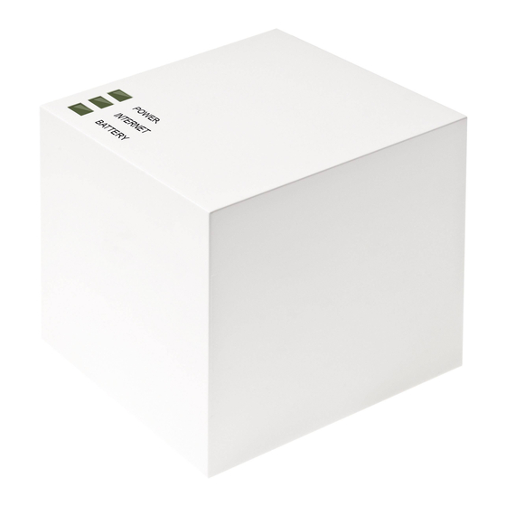
Seite 4: Übersicht
2. Übersicht Oberseite Power: Die LED zeigt an, ob eine Stromversorgung besteht und das Gerät betriebsbereit ist. Internet: Die LED signalisiert, ob eine Verbindung zum Netzwerk/MAX! Por- tal besteht. Battery: Die LED zeigt an, ob bei ei- ner MAX! Komponente die Batterie auszutauschen ist. -
Seite 5: Sicherheitshinweise
Das CE-Zeichen ist ein Freiverkehrszeichen, das sich ausschließlich an die Behörden wendet und keine Zusicherung von Eigenschaften beinhaltet. 5. Montage Der MAX! Cube kann an der Wand befestigt oder stehend betrieben werden. Zur Wandmontage des MAX! Cubes verwenden Sie die Wandhalterung: •... -
Seite 6: Einrichten Des Max! Systems
Sie bitte ausschließlich das mitgelieferte Originalnetzteil für die Stromversorgung. • Stecken Sie das mitgelieferte USB-Netzteil in eine Steckdose. • Verbinden Sie den MAX! Cube und das Netzteil mit dem USB-Kabel. Verwenden Sie hierzu die seitlich ange- brachte USB-Anschlussbuchse (2) (vgl. Grafik S. 4). - Seite 7 Stromversor- gung besteht. 2. MAX! Cube an Router/PC anschließen: • Verbinden Sie den MAX! Cube mit einem Router. Ste- cken Sie dazu das mitgelieferte Netzwerkkabel in die dafür vorgesehene Buchse (1) seitlich am MAX! Cube (vgl.
-
Seite 8: Installation Der Max! Software
MAX! Eco Taster und als zentraler Datenspeicher. 6.2 Installation der MAX! Software / Systemvoraussetzungen Sie benötigen die MAX! Software, um über den MAX! Cube MAX! Komponenten anzulernen, zu konfigurieren und um Statusmeldungen der Geräte abzurufen. Der MAX! Cube muss für die Installation der MAX! Software mit Strom versorgt und mit einem Router verbunden sein. -
Seite 9: Installation Der Geräte
• Montieren Sie das Gerät, das Sie an das MAX! System anlernen möchten (z.B. MAX! Heizkörperthermostat) ge- mäß der entsprechenden Bedienungsanleitung. • Bringen Sie den MAX! Cube über „Neues Gerät“ in der Software in den Anlernmodus. • Bringen Sie das Gerät, das Sie an das MAX! System anlernen möchten (z.B. -
Seite 10: Internetsteuerung Einrichten
Sie können Ihr MAX! System jetzt flexibel steuern und konfigurieren und sowohl von Zuhause als auch über das Internet darauf zugreifen. 7. Werkseinstellungen wieder herstellen Der Auslieferungszustand des MAX! Cube kann manuell wieder hergestellt werden. Bei der Wiederherstellung der Werkseinstellungen gehen alle vorgenomme- nen Einstellungen und In- formationen über ange-... -
Seite 11: Led-Blinkfolgen Und Sendeverhalten
• Die Power-LED leuchtet wieder permanent. Die Werkseinstellungen sind nun wieder hergestellt. 8. LED-Blinkfolgen und Sendeverhalten Zustand Bedeutung Power- LED aus Stromversorgung unterbrochen LED blinkt MAX! Cube startet und führt Selbsttest durch Selbsttest erfolgreich leuchtet abgeschlossen und die dauerhaft Stromversorgung besteht Internet- LED aus Keine Verbindung zum Netzwerk (Verkabelung prüfen!) -
Seite 12: Hinweise Zum Funkbetrieb
Empfänger spielen Umwelteinflüsse wie Luftfeuchtigkeit neben baulichen Gegebenheiten eine wichtige Rolle. Hiermit erklärt die eQ-3 Entwicklung GmbH, dass sich die- ses Gerät in Übereinstimmung mit den grundlegenden An- forderungen und den anderen relevanten Vorschriften der Richtlinie 1999/5/EG befindet. Die vollständige Konformi- tätserklärung finden Sie unter www.eQ-3.de. -
Seite 13: Technische Eigenschaften
11. Technische Eigenschaften Spannungsversorgung: Input:100 V - 240 V~ / 350 mA (Netzteil) Output: 5V= / 550mA Gehäusemaße (BxHxT): 80 x 80 x 80 mm Funkfrequenz: 868,3 MHz Empfängerklasse: SRD Class 2 Schutzart: IP20 Typische Freifeldreichweite: 100m Schnittstelle: RJ-45 (Ethernet) Farbe: weiß... - Seite 28 AG Maiburger Straße 29 D-26789 Leer www.eQ-3.com...