3B SCIENTIFIC PHYSICS Gastriode S Bedienungsanleitung
Inhaltsverzeichnis
Quicklinks
3B SCIENTIFIC
Bedienungsanleitung
04/08 ALF
1. Sicherheitshinweise
Glühkatodenröhren sind dünnwandige, evakuierte
Glaskolben. Vorsichtig behandeln: Implosionsge-
fahr!
•
Röhre keinen mechanischen Belastungen aus-
setzen.
•
Verbindungskabeln
aussetzen.
Zu hohe Spannungen, Ströme sowie falsche Kato-
denheiztemperatur können zur Zerstörung der
Röhre führen.
•
Die angegebenen Betriebsparameter einhalten.
Beim Betrieb der Röhren können am Anschlussfeld
berührungsgefährliche Spannungen und Hoch-
spannungen anliegen.
•
Schaltungen nur bei ausgeschalteten Versor-
gungsgeräten vornehmen.
•
Röhren nur bei ausgeschalteten Versorgungs-
geräten ein- und ausbauen.
Im Betrieb wird der Röhrenhals erwärmt.
•
Röhre vor dem Ausbau abkühlen lassen.
Die Röhre darf nur im Röhrenhalter S (U185001)
eingesetzt werden.
®
PHYSICS
Gastriode S U18557
keinen
Zugbelastungen
Die Einhaltung der EC Richtlinie zur elektromagne-
tischen Verträglichkeit ist nur mit den empfohle-
nen Netzgeräten garantiert.
2. Beschreibung
Die Gasriode ermöglicht die Aufnahme der I
Kennlinie eines Thyratrons, Beobachtung der selb-
ständigen und unselbständigen Entladung sowie
der diskontinuierlichen Energieabgabe von He-
Atomen beim unelastischen Stoß mit freien Elekt-
ronen.
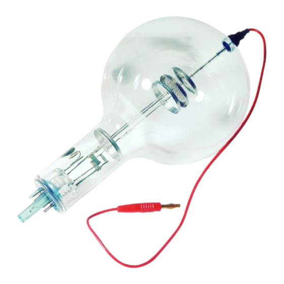
Die Gastriode ist eine mit Helium befüllte Röhre
mit einem Heizfaden (Katode) aus reinem Wolfram,
einer runden Metallplatte (Anode) und einem da-
zwischen liegenden Drahtgitter in einem durch-
sichtigen Glaskolben. Katode, Anode und Drahtgit-
ter sind parallel zueinander angeordnet. Diese
planare Bauform entspricht dem herkömmlichen
Triodensymbol. Eine an einer der Heizfadenzufüh-
rungen befestigte runde Metallplatte sorgt für ein
gleichförmigeres elektrisches Feld zwischen Katode
und Anode.
1
1
4-mm-Steckerstift zum
Anschluss der Anode
2
Anode
3
Gitter
4
Heizwendel
5
Katodenplatte
6
Stiftkontakte
7
Führungsstift
– U
A
–
A
Inhaltsverzeichnis

Verwandte Anleitungen für 3B SCIENTIFIC PHYSICS Gastriode S


Inhaltszusammenfassung für 3B SCIENTIFIC PHYSICS Gastriode S
- Seite 1 ® 3B SCIENTIFIC PHYSICS Gastriode S U18557 Bedienungsanleitung 04/08 ALF 4-mm-Steckerstift zum Anschluss der Anode Anode Gitter Heizwendel Katodenplatte Stiftkontakte Führungsstift Die Einhaltung der EC Richtlinie zur elektromagne- 1. Sicherheitshinweise tischen Verträglichkeit ist nur mit den empfohle- Glühkatodenröhren sind dünnwandige, evakuierte nen Netzgeräten garantiert.
-
Seite 2: Einsetzen Der Röhre In Den Röhrenhalter
• Anodenspannung U in 10 V Schritten von 0 auf 3. Technische Daten 50 V dann in 50 V Schritten auf 250 V erhöhen Gasfüllung: Helium und jeweils die Werte für den zugehörigen A- nodenstrom I messen. ≤ 7,5 V AC/DC Heizung: Bei etwa 25 V steigt der Anodenstrom I in der Gas-... -
Seite 3: Unelastischer Stoß Von Elektronen Mit He-Atomen
• In einem weiteren Versuch kann gezeigt werden, Gitterspannung U in 2 V Schritten auf 0 V dass eine durch unselbständige Zündung eingelei- erhöhen und dann wieder auf -20 V zurückge- tete Gasentladung in selbständiger Entladung fort- hen. Dabei den Verlauf des Anodenstroms I besteht. - Seite 4 • • Versuche mit einer Anodenspannung zwischen Durch Zählen der Leuchterscheinungen und 100 V und 150 V durchführen. Messung der Zeit mit einer Stoppuhr die Kipp- frequenz bei verschiedenen Anoden- und Git- • In jedem Versuch die Gitterspannung langsam terspannungen ermitteln. erhöhen bis die Gasentladung startet.
- Seite 5 Fig.3 UV-Licht als Ionisator Fig. 4 Unelastischer Stoß von Elektronen mit He-Atomen...
- Seite 6 Fig. 5a Aufnahme der I – U – Kennlinie eines Thyratrons Fig. 5b Fig. 6 Thyratron als Gleichrichter...
- Seite 7 Fig. 7 Thyratron als Kippschalter A TELTRON Product from UK3B Scientific Ltd. • 8 Beaconsfield Road • Weston-super-Mare • Somerset BS23 1YE Tel 0044 (0)1934 425333 • Fax 0044 (0)1934 425334 • e-mail uk3bs@3bscientific.com Technische Änderungen vorbehalten © Copyright 2008 3B Scientific GmbH...
-
Seite 9: Instruction Sheet
® 3B SCIENTIFIC PHYSICS Gas Triode S U18557 Instruction sheet 04/08 ALF 4-mm plug for connecting anode Anode Grid Heater filament Cathode plate Connection pins Guide pin The compliance with the EC directive on electro- 1. Safety instructions magnetic compatibility is only guaranteed when Hot cathode tubes are thin-walled, highly evacu- using the recommended power supplies. -
Seite 10: Setting Up The Tube In The Tube Holder
steps. For each step measure the correspond- 3. Technical data ing anode current I Gas filling: Helium At about 25 V the anode current I increases con- ≤ 7.5 V AC/DC Filament voltage: siderably in the gas triode. This increase is accom- panied by the appearance of a blue luminescence. - Seite 11 • Another experiment can show how an excited dis- Increase the grid voltage U to 0 V in steps of charge can continue without the exciting trigger. 2 V then go back to -20 V. Plot the change in the anode current I •...
- Seite 12 minescence and the simultaneous reduction of As the striking voltage decreases (i.e. increasing the capacitor voltage. grid voltage) the frequency gets larger. • By counting the instances of luminescence and measuring the time with a stopwatch, deter- mine the frequency of oscillation for various anode and grid potentials.
- Seite 13 Fig.3 Ionisation by UV light Fig. 4 Inelastic collisions between electrons and helium atoms...
- Seite 14 Fig. 5a Recording the I – U characteristic of a thyratron Fig. 5b Fig. 6 Thyratron rectifier...
- Seite 15 Thyratron oscillator Fig. 7 A TELTRON Product from UK3B Scientific Ltd. • 8 Beaconsfield Road • Weston-super-Mare • Somerset BS23 1YE Tel 0044 (0)1934 425333 • Fax 0044 (0)1934 425334 • e-mail uk3bs@3bscientific.com Technical amendments are possible © Copyright 2008 3B Scientific GmbH...
- Seite 17 3B SCIENTIFIC ® PHYSICS Triode à gaz D U18557 Manuel d'utilisation 04/08 ALF Contact de 4 mm pour la connexion de l'anode Anode Grille Filament Cathode Contacts Pointe Le tube n'a le droit d'être utilisé que dans le sup- 1. Consignes de sécurité port pour tube S (U185001).
- Seite 18 • Appliquez une tension de chauffage de 6 V et 3. Caractéristiques techniques attendez environ une minute, jusqu'à ce que la Remplissage de gaz : hélium température du filament chauffant se soit sta- bilisée. ≤ 7,5 V CA/CC Tension de chauffage : •...
- Seite 19 • Pour étudier la fonction de grille, le courant ano- Augmentez lentement la tension anodique U et déterminez la tension d'allumage U pour la dique I est déterminé avec une tension anodique constante en fonction de la tension de grille U décharge de gaz.
- Seite 20 de la tension de grille négative U , qui influence la Un bref éclairage et un recul simultané de la ten- tension d'allumage U . C'est donc en variant la sion du condensateur caractérisent le processus d'allumage. tension de grille qu'on peut modifier la fréquence de balayage f.
- Seite 21 Fig. 2 Démonstration des porteurs de charge positifs Fig.3 La lumière UV comme ionisateur...
- Seite 22 Fig. 4 Choc inélastique d'électrons avec des ato-mes He Fig. 5a Enregistrement de la caractéristique I – U d'un thyratron – Fig. 5b...
- Seite 23 Fig. 6 Thyratron comme redresseur Fig. 7 Thyratron comme interrupteur basculant A TELTRON Product from UK3B Scientific Ltd. ▪ 8 Beaconsfield Road ▪ Weston-super-Mare ▪ Somerset BS23 1YE Tel 0044 (0)1934 425333 ▪ Fax 0044 (0)1934 425334 ▪ e-mail uk3bs@3bscientific.com Sous réserve de modifications techniques ©...
- Seite 25 3B SCIENTIFIC ® PHYSICS Triodo a gas S U18557 Istruzioni per l'uso 04/08 ALF Spinotto di guida Contatti spinotto Piastra catodica Spirale riscaldante Reticolo Anodo Spinotto da 4 mm per il collegamento dell'anodo Il rispetto della Direttiva CE per la compatibilità 1.
- Seite 26 • Applicare la tensione di innesco di 6 V e atten- 3. Dati tecnici dere ca. 1 minuto fino a quando la temperatu- Gas: Elio ra del filamento incandescente si stabilizza. Tensione di riscaldamento: ≤ 7,5 V CA/CC • Aumentare la tensione anodica U in fasi di 10 V da 0 a 50 V, quindi in fasi di 50 V fino a 250 V Tensione anodica:...
-
Seite 27: Caratteristiche Di Un Tiratron
• 5.4 Caratteristiche di un tiratron Aumentare lentamente la tensione anodica U e determinare la tensione di innesco U per la 5.4.1 Registrazione della caratteristica I – U di un scarica di gas. tiratron • Abbassare nuovamente la tensione anodica U Per l’analisi della funzione del reticolo viene de- fino ad arrestare la scarica indipendente. - Seite 28 • innesco U , il condensatore scarica molto veloce- Per ciascuna prova aumentare lentamente la mente. Se la tensione del condensatore è scesa fino tensione del reticolo fino ad avviare la scarica alla tensione di estinzione U , il processo di condu- di gas.
- Seite 29 Fig. 2 Dimostrazione dei portatori di carica positivi Fig.3 Luce UV come ionizzatore...
- Seite 30 Fig. 4 Urto anelastico di elettroni contro atomi di elio Fig. 5a Registrazione della caratteristica I – U di un tiratron Fig. 5b...
- Seite 31 Fig. 6 Tiratron come raddrizzatore Fig. 7 Tiratron come interruttore a levetta A TELTRON Product from UK3B Scientific Ltd. • 8 Beaconsfield Road • Weston-super-Mare • Somerset BS23 1YE Tel 0044 (0)1934 425333 • Fax 0044 (0)1934 425334 • e-mail uk3bs@3bscientific.com Con riserva di modifiche tecniche ©...
- Seite 33 3B SCIENTIFIC ® PHYSICS Triodo de gas S U18557 Instrucciones de manejo 04/08 ALF Clavija guía Clavijas de contacto Placa de cátodo Espiral de calefacción Rejilla Ánodo 7 Espiga enchufable de 4-mm para la conexión del ánodo • De ser necesario, permita que los tubos se 1.
- Seite 34 planar corresponde al símbolo tradicional de un posible deducir el número de portadores de carga tríodo. Una placa metálica redonda fijada en una que se generan durante la descarga del gas que de las entradas de alimentación del filamento tiene lugar por la ionización por choques entre los calefactor hace que se cree un campo eléctrico electrones y los átomos de helio.
- Seite 35 descarga del gas continua también sin la átomos de He son excitados y emiten cuantos de iluminación. luz. Con un aumento adicional de la tensión de aceleración U , la corriente ánodo I vuelve a 5.2 Determinación de las tensiones de encen- aumentar y después de otros 20 V aprox.
- Seite 36 • • Con una tensión de rejilla U de 0 V se conecta Montaje experimental según fig. 7. Se oscure- la tensión de ánodo. ce el recinto. • • Se disminuye la tensión de rejilla hasta -20 V. Se ajusta la tensión de rejilla U en -20 V.
- Seite 37 Fig. 2 Comprobación de los portadores de carga positivos Fig.3 Luz UV como ionizador...
- Seite 38 Fig. 4 Choques inelásticos de electrones con átomos de He Fig. 5a Registro de la curva característica I – U de un tiratrón Fig. 5b...
- Seite 39 Fig. 6 El tiratrón como rectificador Fig. 7 Tiratrón como interruptor basculante A TELTRON Product from UK3B Scientific Ltd. • 8 Beaconsfield Road • Weston-super-Mare • Somerset BS23 1YE Tel 0044 (0)1934 425333 • Fax 0044 (0)1934 425334 • e-mail uk3bs@3bscientific.com Se reservan las modificaciones técnicas ©...
-
Seite 41: Instruções Para O Uso
3B SCIENTIFIC ® PHYSICS Triodo a gás S U18557 Instruções para o uso 04/08 ALF 1 Pino de condução Contatos de pino Placa catódica Espiral de aquecimento Grade Ânodo Pino de conexão de 4 mm para a conexão da ânodo •... - Seite 42 triodo. Uma placa redonda afixada em uma das ignição de descarga de gás por ionização de linhas de alimentação de aquecimento provê um impacto, os elétrons e átomos de hélio assim campo elétrico uniforme entre o catodo e o anodo. formados.
- Seite 43 então o processo de descarga de gás se dará assim elasticidade com os átomos do hélio e doam mesmo, sem iluminação. energia cinética. Os átomos do hélio são excitados por esse processo e emitem partículas quânticas. Durante um novo aumento da tensão de 5.2 Determinação da tensão de ignição e aceleração U a corrente I...
- Seite 44 • • Conectar a tensão de aquecimento. Montagem da experiência segundo fig. 7. Escurecer o ambiente. • Instalar tensão do anodo onde existir tensão de • grade U de 0 V. Ajustar tensão de grade U de -20 V . •...
- Seite 45 Fig. 2 Prova do transportador de carga positiva Fig.3 UV-Luz como ionizador...
- Seite 46 Fig. 4 Impacto sem elasticidade de elétrons com átomos de hélio Fig. 5a Aceitação da I – U – linha de referência de um Thyratrons Fig. 5b...
- Seite 47 Fig. 6 Thyratron como ponto de alinhamento Fig. 7 Thyratron como interruptor basculante A TELTRON Product from UK3B Scientific Ltd. • 8 Beaconsfield Road • Weston-super-Mare • Somerset BS23 1YE Tel 0044 (0)1934 425333 • Fax 0044 (0)1934 425334 • e-mail uk3bs@3bscientific.com Sob reserva de alterações técnicas ©...