Werbung
Verfügbare Sprachen
Verfügbare Sprachen
Quicklinks
ThermomËtre Infrarouge + Couple K
■
■ Infrared thermometer + K couple
■ Infrarot-Thermometer mit K-Thermoelement
■ Termometro a infrarossi + Termocoppia K
■ TermÛmetro infrarrojo + Captador termo-par K
F R A N « A I S
Notice de fonctionnement
E N G L I S H
User's manual
D E U T S C H
Bedienungsanleitung
I T A L I A N O
Libretto díIstruzioni
E S P A N O L
Manual de Instrucciones
C.A 876
1
Werbung

Verwandte Anleitungen für Chauvin Arnoux P01.6514.03Z


Inhaltszusammenfassung für Chauvin Arnoux P01.6514.03Z
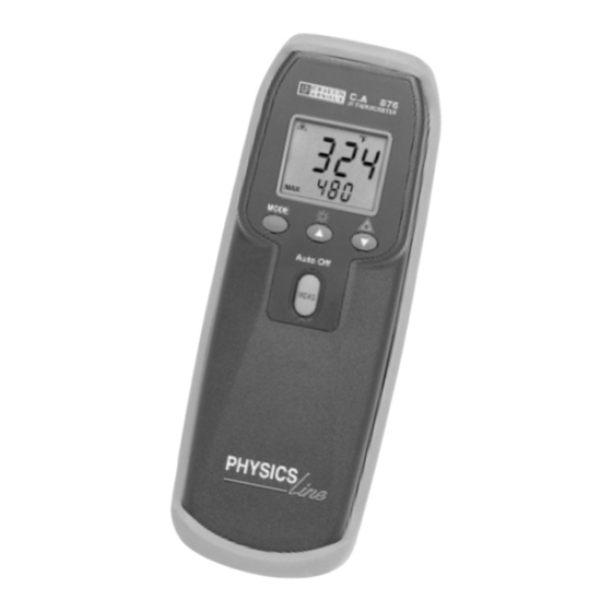
- Seite 1 C.A 876 ThermomËtre Infrarouge + Couple K ■ ■ Infrared thermometer + K couple ■ Infrarot-Thermometer mit K-Thermoelement ■ Termometro a infrarossi + Termocoppia K ■ TermÛmetro infrarrojo + Captador termo-par K F R A N « A I S Notice de fonctionnement E N G L I S H User's manual...
- Seite 2 Significations du symbole ATTENTION†! Consulter la notice de fonctionnement avant díutiliser líappareil. Dans la prÈsente notice de fonctionnement, les instructions prÈcÈdÈes de ce symbole, si elles ne sont pas bien respectÈes ou rÈalisÈes, peuvent occasionner un accident corporel ou endommager líappareil et les installations.
- Seite 3 SOMMAIRE PRESENTATION ................. 3 FONCTIONNEMENT - EMISSIVITE ..........3 DESCRIPTION ................4 UTILISATION ................5 CARACTERISTIQUES ..............8 CAPTEURS ................. 9 MAINTENANCE ................10 POUR COMMANDER ..............11 TABLEAU D'EMISSIVITE............12 ANNEXE................12 1. PRESENTATION Le thermomËtre infrarouge C.A 876 est un appareil de mesure de tempÈrature portatif, simple ‡...
- Seite 4 3. DESCRIPTION DE L'APPAREIL Voir ß 10. Annexe (‡ la fin de la notice de fonctionnement) ➀ ➀ ➀ ➀ ➀ Lentille de mesure infrarouge. ➁ ➁ ➁ ➁ ➁ Orifice du viseur laser. ➂ ➂ ➂ ➂ ➂ Embase pour capteurs thermocouples de type K. ➃...
- Seite 5 4. UTILISATION Recommandations pour les mesures en infra-rouge ● Si le diamËtre de la surface mesurÈe est infÈrieur ‡ 20 ou 50 mm de diamËtre, placer alors le capteur infra-rouge aussi prËs que possible de la surface cible, cíest ‡ dire ‡ moins de 20 ou 50 cm de distance.Voir líinformation sur le champ de vision ( rapport distance de la cible / diamËtre du champ de mesure ) dans le chapÓtre 5 ëCaractÈristiquesí.
- Seite 6 La mesure de tempÈrature est effective aussi longtemps que líon appuie sur la touche ëMEASí. Quand la touche est relachÈe , la mesure reste affichÈe pendant 15‡ 20 secondes. Une fois les mesures rÈalisÈes, retirer le thermocouple de líappareil, qui s†ëÈteindra automatiquement aprËs 15-20 secondes. Remarque†: les mesures infra-rouges sont actives en mÍme temps que les mesures par thermo-couple.
- Seite 7 Quand la tempÈrature atteint et descend en dessous de ce seuil bas, un son est Èmis et ëALM Loí est affichÈ sur líÈcran. MAX†: la valeur maximale pendant la pÈriode effective de mesure est affichÈe. Pendant une mesure et positionnÈ en mode MAX, les appuis sur la touche MODE font basculer successivement líappareil en mode†: MAX ñ...
- Seite 8 5. CARACTERISTIQUES CaractÈristiques Èlectriques Mesure en infra-rouge ● UnitÈ de mesure†: au choix en ∞C ou ∞F. ● Gamme de mesure en tempÈrature†: -20∞C ‡ 550 ∞C (-4 ∞F ‡ 1022 ∞F ) ● RÈsolution†: 0.1∞C/∞F ou 1∞C/∞F PrÈcision†: ± 2 % de la lecture ou ± 6∞F / 3∞C ( la plus grande des ●...
- Seite 9 ● SÈcuritȆ: EN61010-1 ( 1995-A2) , protection classeIII CatÈgorie de surtension ( CAT III, 24 V), pollution degrÈ 2, usage intÈrieur. 6. CAPTEURS Les capteurs thermocouples K suivants peuvent Ítre utilisÈs sur les thermomËtres C.A 861, C.A 863 et C.A 876. Capteurs avec poignÈe et cordon spirale extensible ModËle RÈfÈrence...
- Seite 10 SK 7 Air P03.6529.07 -50...+250∞C ÿ 5 - L = 150 Pour mesures d'air ambiant. Couple protÈgÈ par une gaine mÈtallique ÿ 8,5 mm 10 s SK 8 Pour tuyauteries P03.6529.08 -50...+140∞C tuyau inox Auto-grip 10 ≤ ÿ ≤ 90 ÿ...
- Seite 11 ● Pour toute intervention sous garantie ou hors garantie, retournez l'appareil ‡ votre distributeur. 8. POUR COMMANDER C.A 876...............P01.6514.03Z Fourni avec une gaine antichoc, une pile 9V, un capteur thermo-couple K et cette notice de fonctionnement. Rechange†: Pile 9 V................P01.1007.32 Capteur SK6 souple............P03.6529.06...
- Seite 12 9. TABLEAU EMISSIVITE Voir page 59 Tableau d'EmissivitÈ. 10. ANNEXE...
- Seite 13 Significance of symbole Warning! Please refer to the Userís Manual before using the instrument. In this Userís Manual ,the instructions preceded by the above symbol, should they not be carried out as shown, can result in a physical accident or damage the instrument and the installations. Significance of the LASER symbol Laser radiation, do not look into the LASER beam.
- Seite 14 CONTENTS PRESENTATION ................ 15 OPERATION - EMISSIVITY ............15 DESCRIPTION ................16 USE ................... 17 SPECIFICATIONS ..............20 SENSORS ................. 21 MAINTENANCE ................22 TO ORDER ................23 EMISSIVITY TABLE...............24 FRONT PANEL..............24 1. PRESENTATION The C.A 876 is a temperature measurement instrument, portable, easy to use, with an interchangeable K-type thermocouple sensor also enabling remote temperature measurement using infrared technology.
- Seite 15 3. DESCRIPTION See ß 10 Front Panel (at the end of the operating manual) ➀ ➀ ➀ ➀ ➀ Infrared measurement lens. ➁ ➁ ➁ ➁ ➁ Laser pointer orifice. ➂ ➂ ➂ ➂ ➂ K-type thermocouple sensor base. ➃ ➃ ➃ ➃ ➃ Backlit liquid crystal display : - Main display : numerical temperature value (±) 3Ω...
- Seite 16 4. USE Recommendations for ir measurements ● If the measured surface target diameter is less than 2î/50mm ÿ, then place the sensor as close as possible to the target surface (<20î/50cm away). See Field of View (FOV) information under Specifications. If the target surface is covered with frost or any matter, clean it ●...
- Seite 17 4.2.3 Setting the temperature scale : ∞C or ∞F The temperature scale is displayed on the upper part of the display. To select the temperature scale: ï ∞F: When the thermometer is OFF, hold down and press MEAS. ∞F will be displayed. ï...
- Seite 18 Note: If the thermometer is OFF, pressing the MEAS button for more than 4 seconds will set the thermometer in the MIN/MAX record mode when powered up. ● Back-Light and Increase Button: Press the button to turn the Back-Light ON. Press the button again to turn the Back-Light OFF.
- Seite 19 5. SPECIFICATIONS Electrical Infrared ● Temperature Scale: Celsius (∞C) or Fahrenheit (∞F) user-selectable ● Temperature Range: -4∞F to 1022∞F (-20∞C to 550∞C) ● Display Resolution: 0.1∞C/∞F or 1∞C/∞F ● Accuracy: ±2% of reading or ±6∞F/3∞C, whichever is greater at 64.4 to 82.4∞F (at 18 to 28∞C) ambient operating temperature.
- Seite 20 ● Battery: Standard 9V battery (NEDA 1604, IEC 6F22 006P , or equivalent) ● Battery Life: 100 hours (continuity) typical with carbon-zinc battery (Back-Light not illuminated) ● Dimensions: 173mm(H) x 60.5mm(W) x 38mm(D) ● Weight: 183g including batteries Safety: EN61010-1 (1995-A2), Protection Class III ●...
- Seite 21 1s/contact SK 6 P03.6529.06 -50...+285∞C 3 s in ÿ 1 - L = 1000 Flexible ambient air Recommended for difficult-to-get-at measurement points SK 7 Air P03.6529.07 -50...+250∞C ÿ 5 - L = 150 For ambient air temperature measurement. Thermocouple protected by 8.5 mm ÿ...
- Seite 22 Agent in your country. Repairs Repairs under or out of guarantee : please return the product to your distributor. 8. TO ORDER C.A 876...............P01.6514.03Z Comes with a shoulder bag, 9 V battery, a K type thermocouple and these operating instructions. Spare parts: Battery................P01.1007.32 SK6 flexible sensor............P03.6529.06...
- Seite 23 9. EMISSIVITY TABLE See p. 59 Emissivity table. 10. FRONT PANEL...
- Seite 24 Bedeutung des Zeichens ACHTUNG! Lesen Sie die Bedienungsanleitung, bevor Sie das Ger‰t benutzen. Werden die Anweisungen in dieser Bedienungsanleitung, denen dieses Symbol vorangestellt ist, nicht beachtet oder eingehalten, kann es zu Verletzungen von Menschen oder Besch‰digungen des Ger‰ts oder der Installationen kommen. Bedeutung des Zeichens LASER Laserstrahlung, nicht in den LASERSTRAHL schauen.
- Seite 25 INHALT VORSTELLUNG ................. 26 FUNKTIONSWEISE - ABSTRAHLUNG ........26 BESCHREIBUNG ............... 27 BENUTZUNG ................28 TECHNISCHE DATEN ..............31 F‹HLER ..................32 WARTUNG ................. 34 BESTELLANGABEN ..............35 ABSTRAHLUNGSTABELLE........36 ANLAGE..............36 1. VORSTELLUNG Das Infrarot-Thermometer C.A 876 ist ein einfach einzusetzendes tragbares Temperaturmessger‰t mit einem austauschbaren Thermoelement des Typs K.
- Seite 26 3. BESCHREIBUNG Siehe ß 10. Anlage (am Ende dieser Bedienungsanleitung) ➀ ➀ ➀ ➀ ➀ Messlinse ➁ ➁ ➁ ➁ ➁ ÷ffnung der LASER-Zielvorrichtung ➂ ➂ ➂ ➂ ➂ Sockel f¸r Thermoelement des Typs K ➃ ➃ ➃ ➃ ➃ Beleuchtete Fl¸ssigkristall-Digitalanzeige: - Hauptanzeige: numerischer Wert (±) der Temperatur...
- Seite 27 4. BENUTZUNG Der Strahl der LASER-Zielvorrichtung darf niemals auf die Augen gerichtet werden. Empfehlungen f¸r die Infrarotmessungen ● Ist der Durchmesser der zu messenden Fl‰che kleiner als 50 mm (2"), halten Sie den Infrarotf¸hler so nahe wie mˆglich an die Zielfl‰che, d.h.
- Seite 28 Dr¸ cken Sie die Taste ´MEASª, um die Messung durchzuf¸hren. Da Thermoelemente eine gewisse Ansprechzeit haben, warten Sie vor dem Ablesen des Messwerts, bis sich die Messung stabilisiert hat. Die Messung wird unter dem Hauptbereich des Bildschirms neben dem Symbol ´Kª angezeigt, da der Hauptbereich des Bildschirms f¸r die Anzeige der Infrarotmessung reserviert ist.
- Seite 29 Die Abstrahlung kann ¸ber die Tasten eingestellt werden. Es wird empfohlen, den Wert f¸r allgemeine Anwendungen von 0,95 einzustellen. ALM Hi: Die Einstellung des oberen Alarmgrenzwerts erfolgt ¸ber die Tasten . Sobald die Temperatur diesen Wert erreicht und ¸berschreitet, wird ein akustisches Signal abgegeben und auf dem Bildschirm wird ´ALM Hiª...
- Seite 30 Der minimale Messabstand betr‰gt 150mm. Bei diesem Abstand betr‰gt die Zielfl‰che einen Durchmesser von 15mm. Durchmesser des Messfeldes Entfernung des Ziels Durchmesser des Messfeldes ÿ 200 mm ÿ 150 ÿ 100 ÿ 50 200 cm Entfernung des Ziels 5. TECHNISCHE DATEN Elektrische Daten Infrarotmessungen Messeinheit: wahlweise ∞C oder ∞F...
- Seite 31 5.2 Allgemeine Daten ● Anzeige: 3 Ω Digits mit LCD (Maximalwert: 1999) ● Klimatische Umgebung: Betrieb: 0 bis 50∞C (32 bis 122 ∞F) und < 80 bis 90 % Feuchte, ohne Kondensation Lagerung: -20 bis +60∞C (-4 bis +140∞F), 0 bis 80 % r. F., ohne Batterie ●...
- Seite 32 F¸hler ohne Handgriff * SK 1 Nadel P03.6529.01 -50...+800∞C ÿ 3 - L = 150 Zum Einstechen in weiche, hochviskose Materialien. SK 2 P03.6529.02 -50...+1.000∞C ÿ 2 - L = 1000 Biegsam Nach Anwendung beliebig verformbar. SK 3 P03.6529.03 -50...+1.000∞C ÿ...
- Seite 33 Verl‰ngerungen und Handgriff Model l Referenz Durchmesser L‰nge CK 1 P03.6529.09* 4 mm V 1 m V Verl‰ngerung Mit Miniaturstecker / -buchse CK 2 P03.6529.10* 4 mm V 1 m V Verl‰ngerung Mit Miniaturstecker / 2 blanken Dr‰hten CK 3 P03.6529.13* 4 mm V 1 m V...
- Seite 34 Sie sich an die Niederlassung Ihres Landes. WARTUNG Reparaturen w‰hrend oder auflerhalb des Garantiezeitraumes : senden Sie die Ger‰te zu Ihrem Wiederverk‰ufer. 8. BESTELLANGABEN C.A 876...............P01.6514.03Z Geliefert mit Stoflschutzh¸lle, einer 9V-Batterie, einem K-Thermoelement und dieser Bedienungsanleitung. Ersatzteil: 9V-Batterie..............P01.1007.32 Flexibles Thermoelement SK6..........P03.6529.06 Zubehˆr:...
- Seite 35 9. ABSTRAHLUNGSTABELLE Siehe Seite 59 Abstrahlungstabelle. 10. ANLAGE...
- Seite 36 Significato del simbolo ATTENZIONE! Prima di utilizzare líapparecchio, si raccomanda di leggere le istruzioni díuso. Nel presente manuale, le istruzioni precedute da questo simbolo, qualora non adeguatamente rispettate o eseguite, possono essere causa di infortuni o danni allíapparecchiatura ed agli impianti. Significato del simbolo LASER Radiazioni laser.
- Seite 37 INDICE INTRODUZIONE ................ 38 FUNZIONAMENTO - FATTORE DI EMISSIONI ......38 DESCRIZIONE ................39 UTILIZZO ................... 40 CARATTERISTICHE ..............43 SENSORE ................. 44 MANUTENZIONE ............... 46 MODALITAí DI ACQUISTO ............47 TABELLA FATTORE DI EMISSIONE MATERIALI......47 ALLEGATO..............48 1. INTRODUZIONE Il termometro a infrarossi C.A 876 Ë un apparecchio portatile, di semplice utilizzo, per la misurazione della temperatura, completo di un sensore a termocoppie di tipo K intercambiabili.
- Seite 38 3. DESCRIZIONE Vedi Cap. 10 ñ Allegato (al termine delle istruzioni di funzionamento) ➀ ➀ ➀ ➀ ➀ Lente di misurazione a infrarossi ➁ ➁ ➁ ➁ ➁ Orifizio del fascio laser ➂ ➂ ➂ ➂ ➂ Base per sensore a termocoppia di tipo K ➃...
- Seite 39 4. UTILIZZO Non indirizzare mai il fascio di luce emesso dal mirino laser verso gli occhi. Consigli per líesecuzione di misurazioni a infrarossi ● Qualora il diametro della superficie misurata sia inferiore a 20 o 50 mm, posizionare il sensore ad infrarossi quanto pi˘ possibile vicino alla superficie di destinazione, vale a dire ad una distanza di almeno 20 o 50 cm.
- Seite 40 Premere il pulsante MEAS per eseguire la misurazione. Considerando che le termocoppie reagiscono dopo un certo tempo, prima di rilevare la misurazione, attendere che sia visualizzata. La misurazione Ë visualizzata sulla parte centrale inferiore dello schermo a lato del simbolo K. La parte centrale dello schermo Ë...
- Seite 41 ε --> ε (Set) --> ALM Hi (Set) --> ALM Lo (Set) --> MAX --> MIN --> K --> ε SET est affichÈ quand la fonction sÈlectionnÈe est paramÈtrable (ε, ALM Hi, ALM Lo ) Nel caso in cui i parametri della funzione selezionata possano essere definiti (E, ALM Hi, ALM Lo), sullo schermo sar‡...
- Seite 42 Rapporto distanza della superficie di destinazione / diametro del campo di misurazione Questo rapporto, denominato anche campo visivo, indica il diametro del campo di misurazione della sonda ad una determinata distanza della superficie di destinazione. XX = 10/1 (vedi figura di seguito riportata). La distanza minima di misura e di 150mm, a questa distanza il diametro del campo di misura e di 15mm.
- Seite 43 Protezione ingresso termocoppia: 24 VCC o 24 Vrm massimo a ● fronte di qualsiasi combinazione di ingressi. Frequenza di misurazione: 2,5 volte / secondo ● ● Connettore in ingresso: connettore standard con mini-termocoppia (contatti díingresso in linea, distanziati 7,9 mm, da centro a centro) ●...
- Seite 44 Sensori senza maniglia * SK 1 Lancetta P03.6529.01 -50...+800∞C ÿ 3 - L = 150 Per penetrazione in prodotto pastoso, viscoso SK 2 P03.6529.02 -50...+1000∞C ÿ 2 - L = 1000 Deformabile Deformabile con líuso SK 3 P03.6529.03 -50...+1000∞C ÿ 4 - L = 500 Semirigido Leggermente deformabile SK 4...
- Seite 45 Prolunghe e maniglia Modello Articolo Diametro Lunghezza CK 1 P03.6529.09* 4 mm Prolunga Con capo a spina maschio / spina femmina CK 2 P03.6529.10* 4 mm Prolunga Con capo a spina maschio / 2 fili denudati CK 3 P03.6529.13* 4 mm Prolunga Con capo a spina DIN 5 pioli / presa femmina CK 4...
- Seite 46 8. MODALIT¿ DI ORDINAZIONE C.A 876................P01.6514.03Z Fornito con guaina antiurto, batteria da 9 V, sensore a termocoppia K e le presenti istruzioni díuso. Parte di ricambio: Batteria da 9 V..............P01. 1007.32 Sensore SK6 flessibile............P03.6529.06 Accessorio: Fare riferimento alla sezione 6, sensori 9.
- Seite 47 10. ALLEGATO...
- Seite 48 Significados del sÌmbolo ATENCION: Consultar el manual de instrucciones antes de utilizar el aparato. En el presente manual de instrucciones, las instrucciones precedidas por este sÌmbolo, si no se respetan o realizan adecuadamente, pueden ocasionar un accidente corporal o daÒar el aparato y las instalaciones. Significados del sÌmbolo LASER Radiaciones l ser, no mirar el haz LASER Potencia LASER <...
- Seite 49 INDICE PRESENTACION ................ 50 FUNCIONAMIENTO ñ EMISIVIDAD ........... 50 DESCRIPCION ................51 UTILIZACION ................52 CARACTERISTICAS ..............55 CAPTADORES ................56 MANTENIMIENTO ..............58 PARA PEDIR ................59 CUADRO DE EMISIVIDAD MATERIALES........ 59 ANEXO..............60 1. PRESENTACION El termÛmetro infrarrojo C.A. 876 es un aparato de medida de temperatura port til, sencillo de utilizar, con un captador termopar de tipo K, intercambiable y que tambiÈn permite una medida de temperatura a distancia con la tecnologÌa infrarroja.
- Seite 50 3. DESCRIPCION Ver ß 10. Anexo (al final del material de instrucciones). ➀ ➀ ➀ ➀ ➀ Lente de medida infrarroja ➁ ➁ ➁ ➁ ➁ Orificio del visor l ser ➂ ➂ ➂ ➂ ➂ Base para captadores termopares de tipo K ➃...
- Seite 51 4. UTILIZACION Recommendaciones para las medidas en infrarrojo ● Si el di metro de la superficie medida es inferior a 20 Û 50 mm de di metro, entonces colocar el captador infrarrojo tan cerca como sea posible de la superficie objetivo, es decir, a menos de 20 Û 50 cms.
- Seite 52 ObservaciÛn: las medidas infrarrojas est n activas al mismo tiempo que las medidas por termopar. Cambio de unidad de medida: ∞C o ∞F 4.2.3 La unidad de medida se visualiza en la parte superior de la pantalla Para escoger la unidad: ∞F†: cuando el termÛmetro est apagado, pulsar el botÛn y el botÛn ëMEASí...
- Seite 53 Durante una medida y posicionado en modo MAX, las pulsaciones de la tecla MODE hacen bascular sucesivamente el aparato a modo: MAX ñ MIN ñ medida normal - MAX MIN†: se visualiza el valor mÌnimo durante el periodo efectivo de la medida Durante una medida y posicionado en modo MAX, las pulsaciones de la tecla MODE hacen bascular sucesivamente el aparato...
- Seite 54 En el caso de puntos de medida de dimensiones reducidas, es importante acercar la sonda a una distancia bastante reducida del objetivo para evitar incluir en el campo de medida otros puntos. 5. CARACTERISTICAS CaracterÌsticas elÈctricas Medidas en infrarrojo Unidad de medida: a elegir en ∞C o ∞F. ●...
- Seite 55 Altitud†: 2000 M m x ● Dimensiones / Peso†: 173 x 60.5 x 38 mm / 183 g con pila ● Compatibilidad electromagnÈtica†: ● EmisiÛn seg˙n EN 50081-1 Ed. 1992 Inmunidad seg˙n EN 50082-1 Ed†. 1992 ● Seguridad†: EN61010-1 ( 1995-A2) , protecciÛn clase III categorÌa de sobretensiÛn ( CAT III, 24 V), contaminaciÛn grado 2, uso interior CAPTADORES...
- Seite 56 Sensores sin empuÒadura * SK 1 Aguja P03.6529.01 -50...+800∞C ÿ 3 - L = 3D 150 Para penetraciÛn en productos pastosos, viscosos SK 2 P03.6529.02 -50...+1000∞C ÿ 2 - L = 3D 1000 Deformable Deformable seg˙n uso SK 3 P03.6529.03 -50...+1000∞C ÿ...
- Seite 57 Prolongadores y empuÒadura Modelo Referencia Di metro Longitud CK 1 P03.6529.09* 4 mm Prolongador Extremos acabados en toma macho / toma hembra CK 2 P03.6529.10* 4 mm Prolongador Extremos acabados en toma macho / 2 cables desnudos CK 3 P03.6529.13* 4 mm Prolongador Extremos acabados en toma DIN 5 pins / toma hembra...
- Seite 58 ReparaciÛn Reparacion en garantÌa y fuera de garantÌa : envie sus aparatos a su distribuidor. 8. PARA PEDIR C.A 876................P01.6514.03Z Suministrado con una funda antichoques, una pila 9V, un captador termo - par K y este manual de instrucciones. Recambio†: Pila 9 V................P01.
- Seite 59 10. FRONT PANEL...