Herunterladen Diese Seite drucken
Genius BRAIN 15 Gebrauchsanleitung
Vorschau ausblenden Andere Handbücher für BRAIN 15:

Werbung

Verfügbare Sprachen
  • DE

Verfügbare Sprachen

  • DEUTSCH, seite 47
ISTRUZIONI PER L'USO - INSTRUCTIONS FOR USE
INSTRUCTIONS POUR L'USAGER - INSTRUCCIONES PARA EL USO
GEBRAUCHSANLEITUNG - GIDS VOOR DE GEBRUIKER

Werbung

loading

Inhaltszusammenfassung für Genius BRAIN 15

  • Seite 1 ISTRUZIONI PER L’USO - INSTRUCTIONS FOR USE INSTRUCTIONS POUR L’USAGER - INSTRUCCIONES PARA EL USO GEBRAUCHSANLEITUNG - GIDS VOOR DE GEBRUIKER...
  • Seite 2 24. Eloigner de la portée des enfants les radiocommandes ou tout autre générateur d’impul- 5. GENIUS declines all liability caused by improper use or use other than that for which the sions, pour éviter tout actionnement involontaire de l’automatisme.
  • Seite 3 2006/95/CE direttiva Bassa Tensione. • 2004/108/CE direttiva Compatibilità Elettromagnetica Nota aggiuntiva: Questo prodotto è stato sottoposto a test in una configurazione tipica omogenea (tutti prodotti di costruzione GENIUS S.p.A.) Grassobbio, 30 Dicembre 2009 L’Amministratore Delegato D. Gianantoni Note per la lettura dell’istruzione Leggere completamente questo manuale di installazione prima di iniziare l’installazione del prodotto.
  • Seite 4 Separare sempre i cavi di alimentazione da quelli di comando e di sicurezza (pulsante, ricevente, fotocellule, ecc.). Per evitare qualsiasi disturbo elettrico utilizzare guaine separate o cavo schermato (con schermo collegato a massa). 2. LAYOUT E COLLEGAMENTI Fig. 1 a La tensione di alimentazione è in relazione alla versione BRAIN 15 acquistata.
  • Seite 5 BRAIN 15 Pagina 3 Guida per l’installatore 3. CARATTERISTICHE TECNICHE 3.2. Descrizione morsettiere Morsetto 230Vac (+6% -10%) - 50Hz Descri- Tensione alimentazione oppure e/o Mor- Dispositivo collegato zione 115Vac (+6% -10%) - 60Hz settiera Tensione alimentazione cen- +24V Alimentazione accessori...
  • Seite 6 Pagina 4 BRAIN 15 Guida per l’installatore 6. MESSA IN FUNZIONE 6.3. Apprendimento tempi - setup 6.1. Verifica dei led Prima di eseguire qualsiasi manovra è necessario ese- guire un ciclo di SETUP La tabella sottostante riporta lo stato dei leds in relazione allo...
  • Seite 7 BRAIN 15 Pagina 5 Guida per l’installatore trascorso il tempo desiderato inviare un comando di OPEN. Tab. 4 - Progammazione funzioni avanzate 10. L’anta 2 inizia la fase di chiusura. 11. Dare un comando di OPEN per definire l’inizio del tratto rallentato ed attendere il raggiungimento della battuta meccanica in chiusura.
  • Seite 8 Pagina 6 BRAIN 15 Guida per l’installatore Le fotocellule sono suddivise in gruppi: Dip1 Tipologia Fotocellule in apertura Max. 6 Fotocellule in chiusura Max. 7 Fotocellule in apertura e chiusura Max. 2 Fotocellula usata come impulso di OPEN Max. 1 CHIUSURA Fig.
  • Seite 9 BRAIN 15 Pagina 7 Guida per l’installatore 7.3. Memorizzazione encoder BUS Per collegare alla centrale un encoder con tecnologia BUS è sufficiente collegare i due fili dell’encoder alla morsettiera J10. La morsettiera non ha polarità, tuttavia la sequenza del collegamen- to definisci a quale anta viene associato l’encoder.
  • Seite 10 Pagina 8 BRAIN 15 Guida per l’installatore 8.2. Memorizzazione dei radiocomandi 433 E’ possibile memorizzare max. 250 codici, divisi fra OPEN A ed OPEN B. Utilizzare i telecomandi 433 solo con modulo ricevente a 433 MHz. Premere il pulsante LOGIC (SW3) o SPEED (SW2), per memorizzare rispettivamente l’apertura totale (OPEN A) o...
  • Seite 11 BRAIN 15 Pagina 9 Guida per l’installatore 11. LOGICHE DI FUNZIONAMENTO Tab. 7 LOGICA “A” IMPULSI STATO AUTOMA- OPEN A OPEN B STOP FSW OP FSW CL FSW CL/OP ZIONE apre e richiude apre l’anta svinco- nessun effetto nessun effetto...
  • Seite 12 Pagina 10 BRAIN 15 Guida per l’installatore Tab. 10 LOGICA “EP” IMPULSI STATO AUTOMA- OPEN A OPEN B STOP FSW OP FSW CL FSW CL/OP ZIONE apre l’anta svin- nessun effetto nessun effetto nessun effetto CHIUSO apre le ante nessun effetto...
  • Seite 13 BRAIN 15 Pagina 11 Guida per l’installatore Tab. 13 LOGICA “C” COMANDI MANTENUTI IMPULSI STATO AUTOMA- OPEN A OPEN B STOP FSW OP FSW CL FSW CL/OP ZIONE nessun effetto nessun effetto nessun effetto CHIUSO apre le ante nessun effetto...
  • Seite 14 2006/95/EC Low Voltage directive. • 2004/108/EC Electromagnetic Compatibility directive. Additional information: This product underwent a test in a typical uniform configuration (all products manufactured by GENIUS S.p.A.). Grassobbio, December 30, 2009 Managing Director D. Gianantoni Notes on reading the instruction Read this installation manual to the full before you begin installing the product.
  • Seite 15 Always separate power cables from control and safety cables (push-button, receiver, photocells, etc.). To avoid any electrical disturbance, use separate sheaths or a screened cable (with the screen earthed). 2. LAYOUT AND CONNECTIONS Fig. 1 a The power supply is related to the BRAIN 15 purchased version.
  • Seite 16 20 the BRAIN 15 equipment. Vac and 26 Vac. Voltage must be measured load free. If the gate detects an obstacle during the opening or closing move- ment, the anti-crushing function activates and reverses the sense 3.1.
  • Seite 17 Before performing the Setup, select the operator con- point is reached. nected to the BRAIN 15 equipment with the DS3 and When at rest, leaf 2 starts the pause time count. At the end DS4 dip-switches.
  • Seite 18 Pagina 16 BRAIN 15 Guide for the installer 13. Send an OPEN command to determine the start of the Tab. 4 - Programming features decelerated part and wait until the closing mechanical stop point is reached. 14. When leaf 1 reaches the closing mechanical stop point, the setup phase is completed.
  • Seite 19 BRAIN 15 Pagina 17 Guide for the installer board. Dip1 Rif. Tipologia The photocells are split into groups: Opening photocells Max. 6 Closing photocells Max. 7 Opening /Closing photocells Max. 2 Photocell used as an OPEN pulse Max. 1 CLOSING Fig.
  • Seite 20 Pagina 18 BRAIN 15 Guide for the installer 7.3. Memorising the BUS encoder To connect a BUS technology encoder to the control unit, simply connect the two encoder wires to terminal board J10. The terminal board does not have a specific polarity, however the connection se- quence determines which leaf the encoder is associated to.
  • Seite 21 BRAIN 15 Pagina 19 Guide for the installer 433 MHz. Press the LOGIC (SW3) or SPEED (SW2) push-button, to memory store respectively total opening (OPEN A) or partial opening (OPEN B), and as you hold it down, also press the SETUP (SW1) push-button.
  • Seite 22 Pagina 20 BRAIN 15 Guide for the installer 11. FUNCTION LOGICS Tab. 7 LOGIC “A” PULSES AUTOMATED SY- OPEN A OPEN B STOP FSW OP FSW CL FSW CL/OP STEM STATUS opens released opens and closes no effect (OPEN no effect (OPEN...
  • Seite 23 BRAIN 15 Pagina 21 Guide for the installer Tab. 10 LOGIC “EP” PULSES AUTOMATED SY- OPEN A OPEN B STOP FSW OP FSW CL FSW CL/OP STEM STATUS opens released no effect (OPEN no effect (OPEN no effect (OPEN CLOSED...
  • Seite 24 Pagina 22 BRAIN 15 Guide for the installer Tab. 13 LOGIC “C” MAINTAINED COMMANDS PULSES AUTOMATED SY- OPEN A OPEN B STOP FSW OP FSW CL FSW CL/OP STEM STATUS no effect (OPEN no effect (OPEN no effect (OPEN CLOSED...
  • Seite 25 2006/95/CE directive Basse Tension. • 2004/108/CE directive Compatibilité Électromagnétique. Note supplémentaire: Ce produit a été testé dans une configuration typique homogène (tous les produits sont fabriqués par GENIUS S.p.A.) Grassobbio, 30 décembre 2009 L’Administrateur Délégué D. Gianantoni Remarques pour la lecture de l’instruction Lire ce manuel d’installation dans son ensemble avant de commencer l’installation du produit.
  • Seite 26 Toujours séparer les câbles d’alimentation des câbles de commande et de sécurité (bouton-poussoir, récepteur, photocel- lules, etc.). Pour éviter toute perturbation électrique, utiliser des gaines séparées ou un câble blindé (blindage connecté à la masse). 2. LAYOUT ET CONNEXIONS Fig. 1 a La tension d’alimentation est en relation avec la version BRAIN 15 achetée.
  • Seite 27 à la BRAIN 15. sortie différentes. Avant la mise en service, toujours Si le portail rencontre un obstacle durant le mouvement d’ouverture vérifier que la tension de sortie sur l’enroulement...
  • Seite 28 Pagina 26 BRAIN 15 Guide pour l’installateur des entrées (en caractères gras la condition d’automatisme Disposer les opérateurs pour le fonctionnement manuel et fermée au repos). les positionner environ à la moitié de l’ouverture souhaitée. Vérifier l’état des LEDs de signalisation d’après le tableau suivant.
  • Seite 29 BRAIN 15 Pagina 27 Guide pour l’installateur à clignoter et il faudra répéter toute la procédure de setup. Tab. 4 - Programmation avancée Avec la procédure de SETUP MANUEL, le retard de vantail en fermeture est sélectionné par défaut. Pour le modifier, exécuter une programmation de second niveau...
  • Seite 30 Pagina 28 BRAIN 15 Guide pour l’installateur 7.1. Adressaga des photocellules BUS Tab. 5 - Adressage des photocellules BUS Il est important de donner la même adresse à l’émetteur Dip-switche Rif. Type et au récepteur. S’assurer qu’il n’y a pas deux ou plusieurs paires de photocellules avec la même adresse.
  • Seite 31 BRAIN 15 Pagina 29 Guide pour l’installateur 7.2. Mémorisation des accessoire BUS LEDs ALLUMÉE CLIGNOTANTE ÉTEINTE À tout moment, on peut ajouter des photocellules BUS à l’instal- Encodeur associé Encodeur associé lation, simplement en les mémorisant sur la platine comme suit:...
  • Seite 32 Pagina 30 BRAIN 15 Guide pour l’installateur tenant enfoncés, simultanément sur les boutons-poussoirs s’éteindront (effacement complété). P1 et P2. Relâcher les deux boutons-poussoirs. La LED de la radiocommande commencera à clignoter. Cette opération N’EST PAS réversible. On effacera tous Relâcher les deux boutons-poussoirs.
  • Seite 33 BRAIN 15 Pagina 31 Guide pour l’installateur 11. LOGIQUES DE FONCTIONNEMENT Tab. 7 LOGIQUE “A” IMPULSIONS ÉTAT OPEN A OPEN B STOP FSW OP FSW CL FSW CL/OP AUTOMATISME ouvre le vantail ouvre et referme dégagé et ferme aucun effet...
  • Seite 34 Pagina 32 BRAIN 15 Guide pour l’installateur Tab. 9 LOGIQUE “AP” IMPULSIONS ÉTAT OPEN A OPEN B STOP FSW OP FSW CL FSW CL/OP AUTOMATISME ouvre le vantail ouvre et referme dégagé et ferme aucun effet aucun effet aucun effet FERMÉ...
  • Seite 35 BRAIN 15 Pagina 33 Guide pour l’installateur Tab. 11 LOGIQUE “A1” IMPULSIONS ÉTAT OPEN A OPEN B STOP FSW OP FSW CL FSW CL/OP AUTOMATISME ouvre le vantail ouvre et referme dégagé et ferme aucun effet aucun effet aucun effet FERMÉ...
  • Seite 36 GENIUS S.p.A. Dirección: Via Padre Elzi, 32 - 24050 - Grassobbio- Bergamo - ITALIA Declara que: El equipo electrónico mod. BRAIN 15 • cumple con los requisitos esenciales de seguridad de las siguientes directivas CEE: • 2006/95/CE directiva de Baja Tensión.
  • Seite 37 Separe siempre los cables de alimentación de los cables de mando y de seguridad (pulsador, receptor, fotocélulas, etc). Para evitar cualquier interferencia eléctrica utilice vainas separadas o un cable blindado (con blindaje conectado a masa). 2. LAYOUT Y CONEXIONES Fig. 1 a La tensiòn de alimentaciòn varia en funciòn del versiòn BRAIN 15 adquirida.
  • Seite 38 La tensiòn de alimentaciòn y el fusible de protecciòn motorizaciones conectadas al BRAIN 15. varian en funciòn de la veriòn adquirida. Si la cancela encuentra un obstáculo durante el movimiento de apertura o de cierre, la función antiaplastamiento se activa e invierte...
  • Seite 39 BRAIN 15 Pagina 37 Guía para el instalador 6. PUESTA EN FUNCIONAMIENTO 6.3. Aprendizaje tiempos - setup Antes de realizar cualquier maniobra es necesario 6.1. Comprobación de los dodos realizar un ciclo de SETUP En la siguiente tabla se indican las configuraciones del interruptor dip DS1 para la programación de la fuerza, del tipo de motor.
  • Seite 40 Pagina 38 BRAIN 15 Guía para el instalador decelerado y espere que la hoja alcance el tope mecánico de apertura. Cuando se ha parado la hoja 2, empieza la cuenta del tiempo de pausa; una vez transcurrido el tiempo deseado envíe un mando de OPEN.
  • Seite 41 BRAIN 15 Pagina 39 Guía para el instalador conector BUS (J10 - fig. 1). Dip-switch Rif. Tipología Pueden conectarse a la tarjeta hasta un máximo de 16 pares de fotocélulas BUS. Las fotocélulas están divididas en grupos: Fotocélulas en apertura Max.
  • Seite 42 Pagina 40 BRAIN 15 Guía para el instalador 7.3. Memorización encoder BUS Para conectar a la central un encoder con tecnología BUS es suficiente conectar los dos hilos del encoder a la regleta de bornes J10. La regleta de bornes no tiene polaridades; no obstante, la secuencia de la conexión define a qué...
  • Seite 43 BRAIN 15 Pagina 41 Guía para el instalador 8.2. Memorización de los radiomandos 433 Se pueden memorizar al máximo 250 códigos, divididos entre OPEN A y OPEN B. Utilice los telemandos 433 sólo con módulo receptor a 433 MHz. Presione el pulsador LOGIC (SW3) o SPEED (SW2), para...
  • Seite 44 Pagina 42 BRAIN 15 Guía para el instalador 11. LÓGICAS DE FUNCIONAMIENTO Tab. 7 LÓGICA “A” IMPULSOS ESTADO DEL OPEN A OPEN B STOP FSW OP FSW CL FSW CL/OP AUTOMATISMO abre la hoja abre y vuelve a desvinculada y cerrar transcurrido ningún efecto...
  • Seite 45 BRAIN 15 Pagina 43 Guía para el instalador Tab. 9 LÓGICA “AP” IMPULSOS ESTADO DEL OPEN A OPEN B STOP FSW OP FSW CL FSW CL/OP AUTOMATISMO abre la hoja abre y vuelve a desvinculada y cerrar transcurrido ningún efecto ningún efecto...
  • Seite 46 Pagina 44 BRAIN 15 Guía para el instalador Tab. 11 LÓGICA “A1” IMPULSOS ESTADO DEL OPEN A OPEN B STOP FSW OP FSW CL FSW CL/OP AUTOMATISMO abre la hoja abre y vuelve a desvinculada y cerrar transcurrido ningún efecto ningún efecto...
  • Seite 47 • 2006/95/EG Niederspannungsrichtlinie. • 2004/108/EG Richtlinie zur elektromagnetischen verträglichkeit. Zusätzliche Anmerkungen: Dieses Produkt wurde in einer typischen, homogenen Konfiguration getestet (alle von GENIUS S.p.A. hergestellten Produkte). Grassobbio, 30. Dezember 2009 Geschäftsführer D. Gianantoni Hinweise zu den Anleitungen Vor der Installation des Produkts sind die Installationsanweisungen vollständig zu lesen.
  • Seite 48 
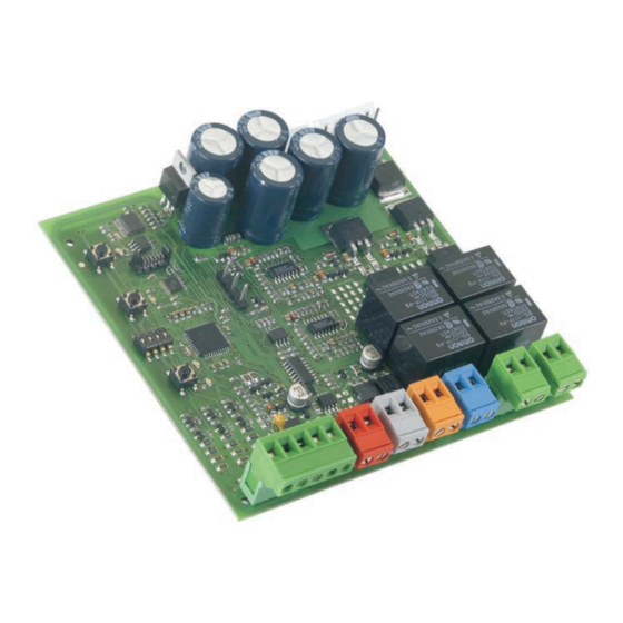
Die Versorgungskabel stets von den Steuer- und Sicherheitskabeln (Taste, Empfänger, Fotozellen usw.) trennen. Um jegliche elektrische Störung zu vermeiden, getrennte Ummantelungen oder abgeschirmte Kabel (mit geerdeter Abschir- mung) verwenden. 2. LAYOUT UND ANSCHLÜSSE Abb. 1 a Die Spannung der Speisung ist in Zusammenhang nit der BRAIN 15 gekauften Ausführung...
  • Seite 49 Ausgangswerte auf den Versorgungsklemmen der chung des Ampereverbrauchs der an E024 angeschlossenen Karte vorliegen. Vor der Inbetriebnahme ist stets zu Antriebe oder des Encoders der an BRAIN 15 angeschlossenen prüfen, ob die Ausgangsspannung auf der Sekundär- Antriebe erzielt. wicklung des Transformators zwischen 20 Vac und 26 Wenn das Tor beim Öffnen oder Schließen auf ein Hindernis...
  • Seite 50 Pagina 48 BRAIN 15 Leitfaden für den Installateur 6. INBETRIEBNAHME 6.3. Alernverfahren der betriebszeiten - setup Vor der Ausführung von Bewegungen muss ein SETUP- 6.1. Überprüfung der led Zyklus gefahren werden. Die unten aufgeführte Tabelle zeigt den Zustand der LED in Bezug auf den Zustand der Eingänge (fett gedruckt ist der Zustand der...
  • Seite 51 BRAIN 15 Pagina 49 Leitfaden für den Installateur Flügel 2 startet die Öffnungsbewegung. Einen OPEN-Befehl senden, um den Beginn des Verlangsa- mungsbereichs festzulegen, und warten, bis der mechani- sche Endanschlag beim Öffnen angefahren wird. Wenn der Flügel 2 stillsteht, beginnt der Ablauf der Pau- senzeit.
  • Seite 52 Pagina 50 BRAIN 15 Leitfaden für den Installateur An die Karte können maximal 16 Paar BUS-Fotozellen angesch- Dip-Switch Bez. lossen werden. Die Fotozellen sind in Gruppen unterteilt: Fotozellen beim Öffnen Max. 6 Fotozellen beim Schließen Max. 7 Fotozellen beim Öffnen/Schließen Max.
  • Seite 53 BRAIN 15 Pagina 51 Leitfaden für den Installateur Fehler in der BUS-Verbindung erfasst, das schnelles Blinklicht Verfahren für die Erfassung wiederholen. (Aufblinken im Ab- Wenn der Fehler erneut auftritt, sicherstellen, stand von 0,2 Sekun- dass in der Anlage keine Zubehörteile mit...
  • Seite 54 Pagina 52 BRAIN 15 Leitfaden für den Installateur 8.2. Einspeicherung der 433-funksteuerungen Maximal 250 Codes, aufgeteilt zwischen OPEN A und OPEN B, können eingespeichert werden. Die 433-Funksteuerungen nur mit Empfängermodul zu 433 MHz verwenden. Die Taste LOGIC (SW3) oder SPEED (SW2) drücken, um jeweils die vollständige Öffnung (OPEN A) bzw.
  • Seite 55 BRAIN 15 Pagina 53 Leitfaden für den Installateur 11. STEUERUNGSLOGIKEN Tab. 7 LOGIK “A” IMPULSE STATUS DER OPEN A OPEN B STOP FSW OP FSW CL FSW CL/OP AUTOMATION öffnet den keine öffnet und schließt freien Flügel GESCHLOS- keine Auswirkung...
  • Seite 56 Pagina 54 BRAIN 15 Leitfaden für den Installateur Tab. 9 LOGIK “AP” IMPULSE STATUS DER OPEN A OPEN B STOP FSW OP FSW CL FSW CL/OP AUTOMATION öffnet den keine öffnet und schließt freien Flügel keine Auswirkung keine Auswirkung Auswirkung...
  • Seite 57 BRAIN 15 Pagina 55 Leitfaden für den Installateur Tab. 11 LOGIK “A1” IMPULSE STATUS DER OPEN A OPEN B STOP FSW OP FSW CL FSW CL/OP AUTOMATION öffnet den öffnet und keine freien Flügel schließt nach keine Auswirkung keine Auswirkung...
  • Seite 58 2006/95/EG Laagspanningsrichtijn. • 2004/108/EG richtlijn Elektromagnetische Compatibiliteit. Aanvullende opmerking: Dit product is getest in een specifieke homogene configuratie (alle door GENIUS S.p.A. vervaardigde producten). Grassobbio, Van de 30 december 2009 De Algemeen Directeur D. Gianantoni Opmerkingen voor het lezen van de instructies Lees deze installatiehandleiding aandachtig door alvorens te beginnen met de installatie van het product.
  • Seite 59 Houd de voedingskabels altijd gescheiden van de kabels voor de bediening en de beveiliging (drukknop, ontvanger, fotocellen, etc.). Om elektrische storingen te vermijden moeten gescheiden kabelmantels of afgeschermde kabels (met scherm aangesloten op de massa) worden gebruikt. 2. LAYOUT EN AANSLUITINGEN Fig. 1 a De voedingddpannig heeft betrekking op de gekochte versie BRAIN 15...
  • Seite 60 De functie van de elektronische anti-inklemmingsbeveiliging wordt verkregen via de controle van het stroomverbruik of van de encoder van de aandrijvingen die zijn aangesloten op BRAIN 15. a De voedingsspanning en de zekering hebben betrek- Als de poort tijdens de openings- of sluitingsbeweging een obstakel king op de gekochte versie.
  • Seite 61 BRAIN 15 Pagina 59 Gids voor de installateur 6.3. Zelflerende procedure tijden - setup 6. INBEDRIJFSTELLING Alvorens enige manoeuvre uit te voeren moet een 6.1. Controle van de leds SETUP-cyclus worden uitgevoerd. In de onderstaande tabel wordt de status van de leds weergege-...
  • Seite 62 Pagina 60 BRAIN 15 Gids voor de installateur en geef na de gewenste tijd een OPEN-commando. 10. Vleugel 2 begint dicht te gaan. 11. Geef een OPEN-commando om aan te geven waar de vertraging moet beginnen, en wacht tot de mechanische aanslag voor het sluiten is bereikt.
  • Seite 63 BRAIN 15 Pagina 61 Gids voor de installateur aangesloten. De fotocellen zijn in groepen verdeeld: Fotocellen voor opening Max. 6 Fotocellen voor sluiting Max. 7 Fotocellen voor opening/sluiting Max. 2 Fotocel die wordt gebruikt als OPEN-impuls Max. 1 SLUITING Fig. 2 OPENING en SLUITING In fig.
  • Seite 64 Pagina 62 BRAIN 15 Gids voor de installateur 7.3. Geheugenopslag encoder met BUS-aansluiting Om een encoder met BUS-technologie op de besturingseenheid aan te sluiten hoeven enkel de twee draden van de encoder op klemmenbord J10 te worden aangesloten. Het klemmenbord heeft geen polariteit, maar de aansluitvolgorde bepaalt met welke vleugel de encoder wordt geassocieerd.
  • Seite 65 BRAIN 15 Pagina 63 Gids voor de installateur 8.2. 433-afstandsbedieningen in het geheugen door te snijden. opslaan Er kunnen max. 250 codes in het geheugen worden opgeslagen, verdeeld tussen OPEN A en OPEN B. Gebruik de 433-afstandsbedieningen uitsluitend met de 433 MHz-ontvangstmodule.
  • Seite 66 Pagina 64 BRAIN 15 Gids voor de installateur 11. BEDRIJFSLOGICA’S Tab. 7 LOGICA “A” IMPULSEN STATUS AUTOMATISCH OPEN A OPEN B STOP FSW OP FSW CL FSW CL/OP SYSTEEM opent de gaat open en losgekoppel- geen effect geen effect geen effect...
  • Seite 67 BRAIN 15 Pagina 65 Gids voor de installateur Tab. 9 LOGICA “AP” IMPULSEN STATUS AUTOMATISCH OPEN A OPEN B STOP FSW OP FSW CL FSW CL/OP SYSTEEM opent de gaat open en losgekoppel- geen effect geen effect geen effect GESLOTEN...
  • Seite 68 Pagina 66 BRAIN 15 Gids voor de installateur Tab. 11 LOGICA “A1” IMPULSEN STATUS AUTOMATISCH OPEN A OPEN B STOP FSW OP FSW CL FSW CL/OP SYSTEEM opent de gaat open en losgekoppel- geen effect geen effect geen effect GESLOTEN...
  • Seite 69 BRAIN 15 Pagina 67 NOTE - NOTES - NOTE - NOTAS - ANMERKUNG - OPMERKINGEN...
  • Seite 70 Pagina 68 BRAIN 15 NOTE - NOTES - NOTE - NOTAS - ANMERKUNG - OPMERKINGEN...
  • Seite 71 9. GENIUS is niet aansprakelijk als de regels der goede techniek niet in acht genomen zijn bij de bouw van het sluitwerk dat gemotoriseerd moet worden, noch voor vervormingen HINWEISE FÜR DEN INSTALLATIONSTECHNIKER...
  • Seite 72 Les descriptions et les illustrations du présent manuel sont fournies à titre indicatif. GENIUS se réserve le droit d’apporter à tout moment les modifications qu’elle jugera utiles sur ce produit tout en conservant les caractéristiques essentielles, sans devoir pour autant mettre à...