Dungs GasMultiBloc MB-VEF B01 Betriebs- Und Montageanleitung
Vorschau ausblenden
Andere Handbücher für GasMultiBloc MB-VEF B01:
- Bedienungsanleitung (16 Seiten) ,
- Betriebs- und montageanleitung (16 Seiten)
Werbung
Quicklinks
���
���
���
�
���
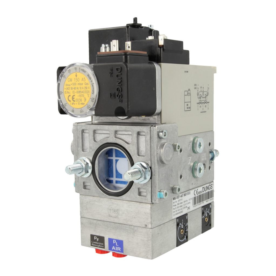
Betriebs- und Montagean-
leitung
GasMultiBloc
®
stufenlos gleitende
Betriebsweise
Typ MB-VEF B01
Nennweiten
Rp 1 1/2 - Rp 2
Einbaulage
Installation position
[mbar]
EN 161
[ V ]
EN 88
1 : 1
V
N
1 ... 16
��
��
��
��
��
�
�
�
��
��
Operation and assembly
instructions
GasMultiBloc
Gas-air-ratio control
Type MB-VEF B01
Nominal diameters
Rp 1 1/2 - Rp 2
Max. Betriebsdruck
Max. operating pressure 360 mbar (36 kPa)
S10: p
5 mbar (0,5 kPa) – p
e,min.
S30: p
100 mbar (10 kPa) – p
e,min.
V1+V2 Klasse A, Gruppe 2
V1+V2 Class A, Group 2
nach / acc. /
EN 161
U
~(AC) 220 V-15 % ...- 230 V+10 %
n
oder/or/
~(AC) 110 V - 120 V, =(DC) 48 V,
=(DC) 24 V - 28 V
Einschaltdauer/Switch-on duration/
100 %
Klasse A, Gruppe 2
Class A, Group 2
nach / acc. /
EN 88, EN 12067-1
Verhältnis
V
ratio
V
p
: p
Br
L
0,75 : 1 ... 3 : 1
Nullpunktkorrektur N
Zero point adjustment N
≈ ± 1 mbar (0,1 kPa)
���
®
Elektrischer Anschluß
Electrical connection
IEC 730-1 (VDE 0631 T1)
360 mbar (36 kPa)
MP
N
1
100 mbar (10 kPa)
e,max.
360 mbar (36 kPa)
e,max.
2
P1
L1
��
���
�
���
IEC 529
IEC 529
Gas Gaz
0,5 - 100 mbar
Erdung nach örtlichen Vorschriften
Grounding acc. local regulations
P1
L1
2
P1
L1
2
MB-VEF 415/420
P1
L1
2
P1
L1
2
MB-VEF 425
Umgebungstemperatur
Ambient temperature
-15 °C ... +70 °C
Schutzart
Degree of protection
IP 54 nach / acc. /
IEC 529 ( DIN 40 050)
Familie 1 + 2 + 3
Family
Ausgangsdruckbereich
Output pressure range
p
0,5 - 100 mbar (0,05 - 10 kPa)
Br
Mp
N
1
Mp
N
1
Mp
N
1
Mp
N
1
1 + 2 + 3
1 + 2 + 3
Werbung

Verwandte Anleitungen für Dungs GasMultiBloc MB-VEF B01


Inhaltszusammenfassung für Dungs GasMultiBloc MB-VEF B01
- Seite 1 �� �� ��� ��� ��� � �� �� �� � � � ��� �� �� ��� Betriebs- und Montagean- Operation and assembly leitung instructions GasMultiBloc GasMultiBloc ® ® stufenlos gleitende Gas-air-ratio control Betriebsweise Typ MB-VEF B01 Type MB-VEF B01 Nennweiten Nominal diameters Rp 1 1/2 - Rp 2 Rp 1 1/2 - Rp 2...
- Seite 2 Einbaumaße / Dimensions / [mm] MB-VEF 415/420 Rp 1 1/2, Rp 2: 283 Rp 1, Rp 1 1/4: 256 Rp 1 1/2, Rp 2: 283 Rp 1, Rp 1 1/4: 256 MB-VEF 425 Platzbedarf für Deckel des Space requirement for pressure Druckwächters switch cover Platzbedarf für Magnetwech-...
- Seite 3 Druckabgriffe Pressure taps MB-VEF 415 MB-VEF 425 MB-VEF 420 min. 5 x DN min. 5 x DN min. 5 x DN min. 5 x DN p , extern MB-VEF 415/420 B01 p , extern PN1, DN 4 PN1, DN 4 p , extern p , extern MB-VEF 415/420 B01...
- Seite 4 Übersicht / Overview / MB-VEF 415/420 17 16 10 12 Impulsleitungen sind nicht Bestandteil des Lieferumfangs. Pulse lines are not part of our scope of delivery. Elektrischer Anschluß Druck- Electrical connection for pressure DIN EN 175 301-803 wächter DIN EN 175 301-803 switch DIN EN 175 301-803 DIN EN 175 301-803 Elektrischer Anschluß...
- Seite 5 Threaded flange version Gewindeflanschausführung MB-VEF B01 MB- VEF B01 Installation and disassembly Ein- und Ausbau 1. Flansche auf die Rohrleitungen 1. Mount flange onto tube lines. montieren. Geeignete Dichtmittel Use appropriate sealing agent verwenden, Bild 1. (see Fig. 1) 2. Insert MB-VEF B01. Note position 2.
- Seite 6 Montagevorschrift Pulse line Impulsleitungen assembly instructions Impulsleitungen p Pulse lines p and p müssen ≥ DN 4 (ø 4 mm), must correspond to ≥ DN 4 PN 1 entsprechen und aus Stahl (4 mm dia.), PN 1 and they must gefertigt sein.
- Seite 7 MB-VEF 425 Einbau Impulsleitungen Installation of pulse lines min. 5 x DN min. 5 x DN min. 5 x DN p , extern p , extern MB-VEF 425 B01 MB-VEF 425 B01 PN1, DN 4 PN1, DN 4 : Gaseingangsdruck : Gas inlet pressure S10: 5 - 100 mbar...
- Seite 8 = 100 mbar L, max. / maxi. = 0,4 mbar 3 : 1 L, min. / mini. max. / maxi. min./mini. = 0,75 : 1 min. / mini. max./maxi. Nullpunktkorrektur ± 1 mbar = 100 mbar Br, max. / maxi. Zero point adjustment ±...
- Seite 9 MB-VEF B01 MB-VEF B01 Einstellung des Druckregelteils Setting the pressure controller Druckregelteil ist werks- Pressure controller is pro- seitig voreingestellt. Die visionally set at the fac- Einstellwerte müssen vor Ort tory. The setting values must den Anlagenbedingungen an- be locally adapted to machine gepaßt werden.
- Seite 10 Option / Option Druckwächter/ Pressure Switch/ Typ/Type/ GW…A5, GW…A2, NB…A2, ÜB…A2 EN 1854 nach / acc. / EN 1854 Setting the gas pressure switch Einstellung des Gasdruckwäch- MB- VEF B01 ters MB- VEF B01 Haube mit geeignetem Werkzeug Dismount the hood using a suitable tool, e.g.
- Seite 11 Filter ist nicht Bestandteil des supply. Lieferumfangs. Install suitable filter upstream. Geeigneter Filter muß vorge- schaltet werden! Insert DUNGS gas filter type GF DUNGS Gasfilter Typ GF 515/1 oder 515/1 or GF 520/1. GF 520/1 einsetzen. MB-VEF 425 B01 MB-VEF 425 B01...
- Seite 12 MB-VEF 415 B01 (Rp 1 1/2 - Rp 1 1/2) Durchfluß-Diagramm1 / Flow Diagram1 / Kurven für Geräteauswahl MB-VEF 415 (im eingeregelten Zustand) mit Feinfilter Curves for equipment selection: MB-VEF 415 (in regulated state) with micro filter empfohlener Arbeitsbereich recommended working range Basis + 15°...
- Seite 13 MB-VEF 420 B01 (Rp 2 - Rp 2) Durchfluß-Diagramm 2 / Flow Diagram 2 / Kurven für Geräteauswahl MB-VEF 420 (im eingeregelten Zustand) mit Feinfilter Curves for equipment selection: MB-VEF 420 (in regulated state) with micro filter empfohlener Arbeitsbereich recommended working range Basis + 15°...
- Seite 14 Durchfluß-Diagramm 4 / Flow Diagram 4 / Mechanisch offen / für Geräteauswahl MB- Durchflußdiagramm 1, 2, 3 anwenden Mechanically open / use flow diagram 1, 2, 3 for MB equipment selection 1 2 4 Basis + 15° C, 1013 mbar, trocken Based on + 15°...
- Seite 15 Arbeiten am GasMulti- Work on the GasMultiBloc Bloc dürfen nur von Fach- may only be performed by personal durchgeführt specialist staff. werden. Flanschflächen schüt- Protect flange surfaces. zen. Tighten screws cross- Schrauben kreuzweise wise. anziehen. Auf spannungsfreien Ein- bau achten! Direkter Kontakt zwi- Do not allow any direct schen GasMultiBloc und...
- Seite 16 Austausch gemäss fol- components according gender Tabelle: to the following table: Sicherheitsrelevante Komponente NUTZUNGSDAUER Schaltspiele Safety relevant component DUNGS empfiehlt den Austausch nach: Operating cycles USEFUL LIFE 和安全相关的组件 操作循环次数 DUNGS recommends replacement after: 使用期限 东斯公司建议更换按照: Ventilprüfsysteme / Valve proving systems 10 Jahre/years 10年...