Nordcap SCN 75 Bedienungsanleitung

Verwandte Anleitungen für Nordcap SCN 75


Inhaltszusammenfassung für Nordcap SCN 75
- Seite 1 SCN 35 SCN 45 SCN 75 SCN 125 SCN 215 Automatic cubers Automatic Kegeleisbereiter 090091.05 - REV. 04/2015...
-
Seite 2: Inhaltsverzeichnis
TABLE OF CONTENTS PAGE INHALTSVERZEICHNIS SEITE GENERAL INFORMATION AND INSTALLATION ALLGEMEINES UND INSTALLATION Introduction Einführung Unpacking and inspection Auspacken und Inspektion Location and levelling Maschinenplatz und lotgerechte Austellung Electrical connection Elektrische Anschlüße Water supply and drain connection Wasserversorgung und Abflußleitungen Final check list Schlußkontrollen Installation practice... - Seite 3 WATER COOLED MODELS - WASSERKÜHLUNG °C °C 10 °C 10 °C WATER TEMPERATURE - WASSERTEMPERATUR WATER TEMPERATURE - WASSERTEMPERATUR SCN 75 AIR COOLED MODELS - LUFTKÜHLUNG WATER COOLED MODELS - WASSERKÜHLUNG °C °C 10 °C 10 °C WATER TEMPERATURE - WASSERTEMPERATUR...
- Seite 4 B/bis Ice making capacity - Eisproduktionskapazität SCN 125 AIR COOLED MODELS - LUFTKÜHLUNG °C 10 °C WATER TEMPERATURE - WASSERTEMPERATUR SCN 215 AIR COOLED MODELS - LUFTKÜHLUNG °C 10 °C WATER TEMPERATURE - WASSERTEMPERATUR...
- Seite 5 SDN 25 - 30 SCN 35 - 45 CORD SET - ELEK. KABEL Ø 20 WATER OUTLET - WASSERABFLUSS G3/4" WATER INLET - WASSEREINLAUF SDN 25 (mm) SDN 30 (mm) SDN 35 (mm) SCN 35 (mm) SCN 45 (mm)
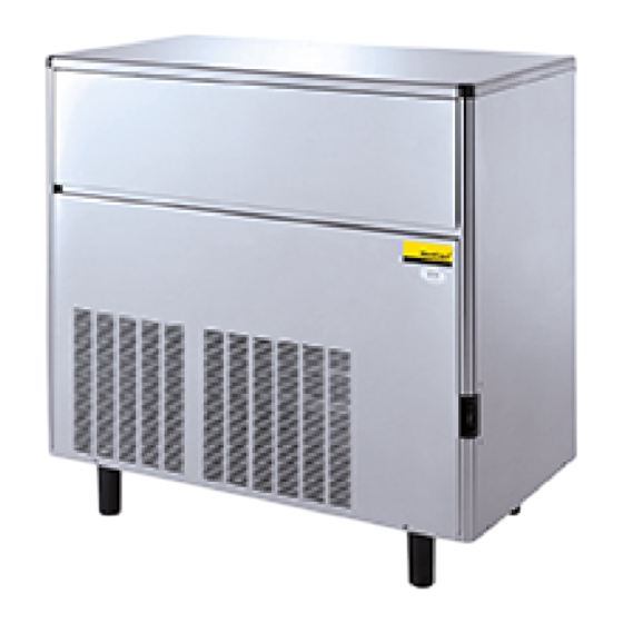
- Seite 6 SCN 75...
- Seite 7 SCN 125...
- Seite 8 SCN 215...
-
Seite 23: Allgemeines Und Installation
Seite 14 ALLGEMEINES UND übereinstimmt, die auf demselben Schild angegeben ist. INSTALLATION ACHTUNG. Bei falscher elektrischer Versorgung erlischt automatisch Ihr EINFÜHRUNG Anrecht auf Garantie. Diese Bedienungsanleitung beschreibt alle Die Garantiekarte im Innern des technischen Angaben, sowie die Reihenfolge für Handbuches ausfüllen und versenden, indem die Installation, Inbetriebnahme und Betrieb, Sie sowohl das Modell, als auch die Wartung... -
Seite 24: Elektrische Anschlüße
S e i t e Man benutzt auch für den Wasseranschluß des ELEKTRISCHE ANSCHLÜSSE Kondensators den flexiblen Schlauch aus verstärktem Plastik, welcher mit dem Gerät Beachten Sie das Schild des Gerätes, um dann geliefert wird und der an ein getrenntes Sperrventil den Querschnitt und das Kabel entsprechend angeschlossen wird. -
Seite 25: Installation
Seite 16 Wurden die Muttern, die den Kompressor die periodische Wartung des Gerätes gegeben? verankern, kontrolliert? Erlauben diese eine Schwingung auf den eigenen Halterungen? 11. Wurde die Garantiekarte ausgefüllt? Seriennummer und das Modell auf dem Schild Wurden die Innenwände des Eisbehälters des Gerätes kontrollieren und dann an den und die Außenwände des Gerätes gesäubert? Hersteller senden. -
Seite 26: Betriebsanleitung
Seite 17 BEDIENUNGSANLEITUNG Durch die Öffnung der Würfelabgabe kontrollieren, daß der Spritzbalken richtig positioniert ist und daß das Wasser gleichmäßig auf die umgedrehten Formen des Verdampfers INBETRIEBNAHME gespritzt wird. Wenn das Gerät richtig installiert und an das Kontrollieren, daß der kleine Plastikvorhang Strom- und Wassernetz angeschlossen ist, korrekt positioniert wurde und den Wasserauslauf folgendermaßen vorgehen:... - Seite 27 Seite 18 Gefrierzyklus hin, oder darauf, daß das Wasser, ANMERKUNG. Wenn dies Kontrolle das für die Produktion benutzt wurde, von während des Gefrierzyklus ausgeführt wird, schlechter Qualität ist und angemessene Filter arbeitet das Gerät bis zum Ende des Zyklus zur Reinigung oder ein Wasserkonditionierer weiter, bis der Mikroschalter des Timers in einzusetzen sind.
-
Seite 28: Funktionssysteme
Seite 19 FUNKTIONSPRINZIP hält dadurch den Ventilator an. Bei Versionen, die mit Luft gekühlt werden (SCN 45), funktioniert der Ventilator ständig und hält den Druck zwischen 8÷ 10 bar. In den Eiswürfelbereitern SIMAG wird das zur Bei den Versionen von SCN 35 bis SCN 45, die Produktion benutzte Wasser ständig von einer mit Wasser gekühlt werden, ist der Druckwächter elektrischen Pumpe in Bewegung gehalten, die... -
Seite 29: Sequenz Der Verschiedenen Befehle
Seite 20 Teil des Verdampfers, wo es durch die ° PHASE GEFRIERZYKLUS Ablaufschlitze in die darunter liegende Sammelwanne der Pumpe fließt. Versorgte elektrische Bauteile... ON OFF Der Maximalstand des Wassers im Tank wird Kompressor ........• von einem Überstandsschlauch begrenzt, Ventilatormotor ...... -
Seite 30: Komponentenbeschrieb
Seite 21 ° PHASE ABTAUZYLUS Da dieses Thermostat mit dem Timerschalter in Serie geschaltet ist, wird das Gerät erst (Zeitbeschränkt) abgeschaltet, wenn das Ende des Gefrierzyklus Versorgte elektrische Bauteile... ON OFF erreicht ist. Auf diese Weise wird sicher gestellt, daß in der Zelle voll geformte Eiswürfel vorhanden Kompressor ........ - Seite 31 Seite 22 Heißgas, das vom Kompressor direkt durch die (SCN 35÷45W) Versionen benutzt und hält den Serpentine des Verdampfers fließt, um die Eingangsdruck des Kühlkreislaufes zwischen den Eiswürfel von den Formen zu lösen, den Weg. beiden eingestellten Werten (8 ÷10 Bar für SCN 35 ÷...
-
Seite 32: Fonktionsfehler
Seite 23 FEHLERSUCHE Problem Möglicher Fehler Lösung Das Gerät funktioniert nicht Hauptschalter aus Hauptschalter anschalten Sicherheitsvorrichtung aktiviert Grund suchen und eliminieren oder ersetzen Elektrische Leitungen nicht Leitungen kontrollieren angeschlossen Kontakte Thermostat Behälter Thermostat ersetzen offen Der Kompressor führt die Niedrige Spannung Stromkreis auf Überlastung Zyklen intermittierend aus kontrollieren... - Seite 33 Seite 24 FEHLERSUCHE Problem Möglicher Fehler Lösung Unregelmäßige und matte Spritzdüsen zum Teil verstopft Die Deckel abnehmen und Eiswürfel säubern Wassermangel Siehe Wassermangel Maschine nicht gut ausgeglichen Maschine gut ausgleichen Zu große Eiswürfel Gefrierzyklus zu lang Das Thermostat des Verdampfers im Gegenuhrzeigersinn drehen Das Thermostat des Verdampfers Thermostat ersetzen...
-
Seite 34: Woraussetzung
Seite 25 ANWEISUNGEN FÜR DIE Das Gerät muß sich nach etwa 20 ÷30“ nach Beendigung des Gefrierzyklus abschalten. WARTUNG UND REINIGUNG ANMERKUNG. Die oben beschriebene Kontrolle nur ausführen, wenn der Gefrierzyklus beendet ist, da während dieses VORAUSSETZUNG Zyklus dieses Thermostat von den Kontakten des Timerschalters überbrückt sind. -
Seite 35: Anweisungen Für Die Reinigung Des Wasserkreislaufes
Seite 26 ANWEISUNGEN FÜR DIE REINIGUNG ANMERKUNG. Während des Reinigungs- DES WASSERKREISLAUFES vorganges, arbeitet nur die Pumpe, damit das Enthärtungsmittel in die Wasserleitungen Die vordere und obere Wandtafel gepumpt werden kann abnehmen, um Zugriff zum Schaltkasten und zum Verdampfer zu haben. Das Gerät etwa 20 Minuten laufen lassen Das Ende des Abtauzyklus abwarten und und dann durch den Hauptschalter abschalten...