
Verwandte Anleitungen für Durr Dental Power Tower Silence 105


Inhaltszusammenfassung für Durr Dental Power Tower Silence 105
- Seite 1 MONTAGE- UND GEBRRAUCHSANWEISUNG DÜRR PTS 105 SCHRANKMODUL VS 900 INSTALLATION AND OPERATING INSTRUCTIONS DÜRR PTS 105 COVER MODULE VS 900 9000- 619- 07/ 01 1999/07...
- Seite 2 Montage- und Gebrauchsanweisung DÜRR Power Tower Silence 105 ........Seite 3-12, 23-25 Installation and Operating Instructions DÜRR Power Tower Silence 105 ........Page 13-25...
-
Seite 3: Inhaltsverzeichnis
MONTAGE- UND GEBRAUCHSANWEISUNG POWER TOWER SILENCE PTS 105 INHALT 1. Hinweise ........... 4 1.1 Sicherheitshinweise ......4 1.2 Elektrische Sicherheitsprüfung ..4 1.3 Elektrischer Anschluß ....... 4 2. Aufgabe ............ 4 3. Typenübersicht ........5 4. Lieferumfang ........... 5 4.1 Zubehör ..........5 4.2 Sonderzubehör ......... -
Seite 4: Hinweise
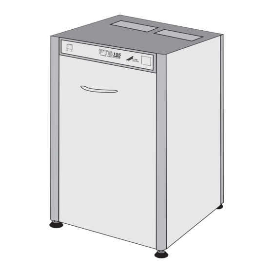
1. HINWEISE 2. AUFGABE 1.1 Sicherheitshinweise Der Power Tower Silence (PTS 105) ist eine Kombination von einer Kombinations-Saug- VOR Beginn der Montagearbeiten einheit VS 900 und einem Amalgamabscheider BITTE BEACHTEN: Typ 7801-08 in einem schallisolierten Schrank. Arbeiten an elektrischen Geräten dürfen Der PTS ist mit schallisolierten Seitenwände nur von qualifizierten Fachkräften (nach ausgestattet die den Geräuschpegel auf ca. -
Seite 5: Typenübersicht
3. TYPENÜBERSICHT 5. TECHNISCHE DATEN Typ Power Tower Silence (PTS 105) VS900 7133- 02 / 20 Schrankmodul, Saugen ....0945-504-52 Nennstrom Amalgamabscheider ......7801-08 Anlaufsstrom Elektr. Leistung 1100 Zentrale Kombinations-Saugeinheit Spannung 400 / 3~ VS900 ........... 7133-02/020 Frequenz (Hz) Max. Flüssigkeits- 4. -
Seite 6: Funktionsbeschreibung
6. FUNKTIONSBESCHREIBUNG • Die in den Deckel eingebrachten Belüftungsschlitze dürfen nicht zugestellt werden. "ÜBERHITZUNGSGEFAHR!" Eine detailierte Funktions- beschreibung der einzelnen Module • Wird der PTS in eine Schrankwand inte- finden Sie in den Anleitungen der griert, sodaß seitlich keine Belüftung einzelnen Geräte! vorhanden ist, so darf der stirnseitige Belüftungsspalt nicht zugestellt werden. -
Seite 7: Einbau Kombinations-Saugeinheit Vs 900
8. EINBAU KOMBINATIONS- SAUGEINHEIT VS 900 Vor der Montage der einzelnen Module ist es von Vorteil wenn die Seitenteile des PTS abgenommen werden und somit von allen Seiten zugänglich ist. (b) wenn der PTS ohne die montierten Module am vorgesehenen Platz ausgerichtet (höhenverstellbare Standbeine) wurde. -
Seite 8: Elektrischer Anschluß
8.2 Elektrischer Anschluß Erfolgt der Anschluß an das Versorgungsnetz über die Boden- oder Deckeninstallation, muß im Stromkreis eine allpolige Trennvorrichtung (allpoliger Schalter oder allpoliger Leitungs- schutzschalter (Sicherung) mit >3mm Kontaktöffnungsweite eingebaut werden. Stromkreisabsicherung: 16 AT (230V) 3 x 16 AT (400V) Der PTS muß... -
Seite 9: Steuerleitung 24V Des Pts
• 230V, 3~ / 400V, 3~ Ausführung Leitung an die dafür vorgesehene Anschlüs- se (7) U, V, W und PE im Motorklemmkasten der VS 900 klemmen. • Gegen Herausreißen durch anziehen der Zugentlastung (8) sichern, s. Bild 5. • Leitung gegen Abrutschen und Berühen der VS 900 sichern. -
Seite 10: Elektrischer Anschluß Des Amalgamabscheiders Im Steuerkasten
10.3 Elektrischer Anschluß des Amalgamabscheiders im Steuer- kasten Der Amalgamabscheider ist zur Füllstandsmessung 1 x täglich aus- und einzuschalten. Dies ist sicher- gestellt wenn der PTS über den Geräte- oder Praxishauptschalter angeschlossen ist, der bei Arbeit- sende abgeschaltet wird. • Vom Amalgamabscheider abgehendes 3- polige Leitung durch die Zugentlastung (11) des Steuerkastens führen. -
Seite 11: Netzanschluß
11. NETZANSCHLUß Das vom Oberteil ausgehende Kabel (N) über eine fest installierte Geräteanschlußdose an das Hausnetz anschließen. 12. ABSCHLUSSARBEITEN • Sämtliche Anschlüsse mit den schon vorbereiteten bauseitigen Anschlüssen verbinden. • Die rückseitige und seitlichen Verkleidungsteile in den PTS einhängen und den PTS auf den dafür vorgesehenen Platz stellen. -
Seite 12: Wartung
13. WARTUNG • Jede Woche Feinfilter im Schlauchhalter wechseln. • Alle 3 Monate Schutzsieb am Sekreteingang der VS 900 reinigen. • Alle 2 Jahre (falls vorhanden) Abluftkeimfilter wechseln. Wartung und Pflege siehe Montageanleitung DÜRR Kombinations-Sauganlage VS 900, Bestell-Nr. 9000-605-84. (Gültig für Über sämtliche Wartungsarbeiten am Amalgamabscheider ist vom Betreiber ein Betriebsbuch zu... - Seite 13 INSTALLATION AND OPERATING INSTRUCTIONS POWER TOWER SILENCE PTS 105 CONTENT 1. Notes ............14 1.1 Safety Notes ........14 1.2 Electrical Safety Test ...... 14 1.3 Electrical Connection ...... 14 2. Purpose of the Power Tower Silence (PTS) ....14 3.
-
Seite 14: Notes
1. NOTES 2. PURPOSE OF THE POWER TOWER SILENCE (PTS) 1.1 Safety Notes PLEASE READ BEFORE ASSEMBLY: The Power Tower Silence (PTS 105) is a combination between combined suction unit Works on electrical devices may only be VS 900 and an amalgam separater model carried out by qualified electrical 7801-08 into a sound insulation covers which specialists (in accordance with VBG4) or by... -
Seite 15: Model Table
3. MODEL TABLE 5. TECHNICAL DATA Model Power Tower Silence (PTS 195) VS900 7133- 02 / 20 Cover Module, Suction ....0947-501-52 Rated current Amalgam Separator (AS) ....7801-08 Start-up current Electrical output 1100 Central Combined Suction Machine Voltage 400 / 3~ VS 900 .......... -
Seite 16: Description Of Features
6. DESCRIPTION OF FEATURES • The ventilation slits in the top cover of the unit must not be covered or blocked: Danger of overheating. Detailed descriptions of the individual modules can be found in the relevant • If the PTS is integrated into a cabinet wall so installation instructions. -
Seite 17: Installation Of Combination Suction Module Vs 900
8. INSTALLATION OF COMBINATION SUCTION MODULE VS 900 Installation of the individual modules is easier if (a) the side covers of the PTS are removed making all sides of the module accessible (b) the PTS is positioned (on the adjustable feet) in its designated place without the individual modules (c) the necessary connections to the PTS have been fitted... -
Seite 18: Electrical Installation
8.2 Electrical Installation With electrical connection to the mains network via the floor or the ceiling , a double pole isolating device (double pole or double pole fused) with > 3 mm contact opening width must be built into the electrical circuit. Fuse requirements: 16 AT 230V / 1~... -
Seite 19: Control Cable 24V Of The Pts
• VS 900 as 230V / 3~ and 400V / 3~ module Connect the leads to the correct terminals (7) PE, U, W and V in the VS 900 motor terminal box. • Adjust the screw (8) to prevent the cable being pulled out, see fig. -
Seite 20: Electrical Connection To Operating Panel
10.3 Electrical Connection to Operating Panel The amalgam separator must be switched on and off once a day in order to check that the amalgam collecting vessel does not need changing. This is provided for when the PTS unit is connected via the main surgery on/off switch which is switched off at the end of surgery hours. -
Seite 21: Mains Connection
11. MAINS CONNECTION • The cable (N) from the upper unit should be connected on firmly junction box with the mains network. 12. FINAL PROCEDURES • Place the side covers into position (the front remains open for further installation) and position the PTS into its correct place. -
Seite 22: Maintenance
13. MAINTENANCE • Every week Change fine filter in manifold. • Every 3 months Clean safety sieve at secretion inlet of VS 900. • Every 2 years Change the exhaust bacterial filter if fitted. For maintenance and cleaning see the installation instructions DÜRR Combination Suction Unit VS 900, 9000-605-84. -
Seite 23: Elektroschema
14. ELEKTROSCHEMA / ELECTRICAL FUNCTIONAL DIAGRAMS Netz (N) l1 l2 l3 N PE X2: 1 2 3 X1: L N PE... -
Seite 24: Schaltplan
15. SCHALTPLAN / ELECTRICAL CIRCUIT DIAGRAMS... -
Seite 25: Medienanschlußplan
16. MEDIEN-ANSCHLUSSPLAN / AIR AND WATER SUPPLY SYSTEM H2 Anzeigenmodul H2 Indicator display A3 Amalgamabscheider A3 Amalgam Separator A2 Steuerkasten A2 Control box M3 Saugmaschine VS900 M3 Suction unit VS900 E1 Lüfter E1 Ventilator Ablage Holder...