Herunterladen Diese Seite drucken

Werbung

Verfügbare Sprachen

Verfügbare Sprachen

Bedienungsanleitung
Operating instructions
Notice d'utilisation
AS-i AirBox
AC5227
AC5228
AC5243

Werbung

loading

Inhaltszusammenfassung für IFM Electronic AS-i AirBox AC5227

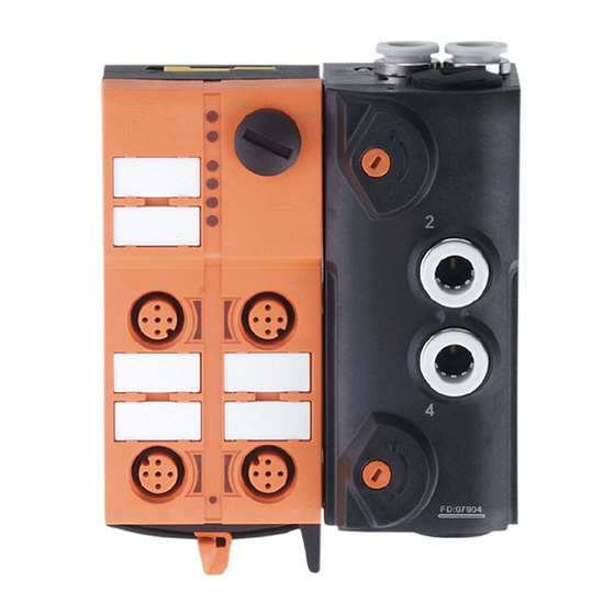
  • Seite 1 Bedienungsanleitung Operating instructions Notice d’utilisation AS-i AirBox AC5227 AC5228 AC5243...
  • Seite 2 Bestimmungsgemäße Verwendung • maximale Anzahl von Modulen pro Master: 31 (AC5227) und 62 (AC5228 / AC5243) • AS-Interface Version 3.0, abwärtskompatibel • Verbindung mit Pneumatik-System über Schlauchsteckverbinder, außenkalibriert nach CETOP-Norm RP 54 P • Betriebsdruckbereich 2...8 bar Der Betrieb außerhalb des angegebenen Betriebsdruckbereiches oder die Verwendung falsch aufbereiteter Druckluft kann zu dauerhaften Undichtigkeiten oder irreparablen Beschädigungen der pneumatischen Bauelemente und zu Fehlfunktionen führen.
  • Seite 3 Montage Hinweise zur Montage ab Seite 26 Adressieren Auslieferungsadresse ist 0. Adressieren mit dem Adressiergerät AC1144 Das Modul kann über die implementierte Adressierschnittstelle mit dem Adressierkabel (E70213) im montierten und verdrahteten Zustand adressiert werden. Wird ein Slave mit dem erweiterten Adressmodus in Kombination mit einem Master der 1.
  • Seite 4 AC5227 2 Eingänge / 2 pneumatische Ausgänge AS-i Profil S-3.F.F / erweiterter Adressmodus: nein Datenbit Eingang Buchse Pneumatik Ausgang Eingänge (Standard) L– AC5228 4 Eingänge / 2 pneumatische Ausgänge AS-i Profil S-7.A.E / erweiterter Adressmodus: ja Datenbit Eingang Buchse I1/2 I1/2 I2 I3/4 I3/4 I4 Pneumatik Ausgang...
  • Seite 5 AC5243 4 Eingänge / 2 pneumatische Ausgänge AS-i Profil S-7.A.E / erweiterter Adressmodus: ja / AUX Datenbit Eingang Buchse I1/2 I1/2 I2 I3/4 I3/4 I4 Pneumatik Ausgang Eingänge (Y-Schaltung) I-1/2 I-3/4 Pneumatik Schaltbild Pneumatik 2x 3/2-Wege Ventil...
  • Seite 6 Druckluft Befolgen Sie die Sicherheitsbestimmungen und Vorschriften für die Einrichtung pneumatischer Anlagen. Schalten Sie die Anlage druckfrei. Verbinden Sie die Anschlüsse für Druckluftzufuhr 1, die Arbeitsan- schlüsse 2 und 4 und gegebenenfalls die Abluft 3 und 5 mit dem pneu- matischen System.
  • Seite 7 3. Maximaler Gesamtölgehalt laut Klasse 1: bei ungeölter Druckluft 0,01 mg / m Maximaler Gesamtölgehalt laut Klasse 4: bei geölter Druckluft < 5 mg / m , das entspricht ca. 1 Öltropfen / 4000 Liter Luft Wurde die AirBox mit geölter Luft betrieben, so muss sie weiterhin mit geölter Luft betrieben werden, da das Öl die Initialschmierung ent- fernt.
  • Seite 8 Betrieb Vermeiden Sie Schmutz- und Staubablagerungen auf Ober- und Unter- teil, um die Verschlussmechanik nicht zu beeinträchtigen. Prüfen Sie, ob das Gerät sicher funktioniert. Anzeige durch LEDs: LED PWR LED FAULT LED 1 LED 2 LED AUX • LED 2 gelb: Eingang geschaltet •...
  • Seite 9 Instandhaltung / Wartung Es dürfen keine Änderungen am Gerät vorgenommen werden; Repa- raturen sind nicht möglich. Wenden Sie sich im Fehlerfall bitte an den Hersteller. Technische Daten Technische Daten und weitere Informationen unter www.ifm-electronic.com --> Select your country --> Datenblatt-Suche...
  • Seite 10 Functions and features • maximum number of modules per master: 31 (AC5227) and 62 (AC5228 / AC5243) • AS-interface version 3.0, downward compatible • connection to the pneumatic system via tube fitting, outside cali- bration according to CETOP standards RP 54 P •...
  • Seite 11 Installation Notes on installation from page 26. Addressing At the factory the address is set to 0. Addressing with the AC1144 addressing unit When mounted and wired the module can be addressed with the addressing cable (E70213) via the implemented addressing interface. If a slave with the extended addressing mode is used in combination with a master of the first generation (version 2.0), the parameter P3 must be 1 and the output bit D3 must be 0*.
  • Seite 12 AC5227 2 inputs / 2 pneumatic outputs AS-i profile S-3.F.F / extended addressing mode: no Data bit Input Socket Pneumatic output Inputs (standard) L– AC5228 4 inputs / 2 pneumatic outputs AS-i profile S-7.A.E / extended addressing mode: yes Data bit Input Socket I1/2...
  • Seite 13 AC5243 4 inputs / 2 pneumatic outputs AS-i Profil S-7.A.E / extended addressing mode: yes / AUX Data bit Input Socket I1/2 I1/2 I2 I3/4 I3/4 I4 Pneumatic output Inputs (Y-circuit) I-1/2 I-3/4 Pneumatics Circuit diagram pneumatics 2x 3/2-way valve...
  • Seite 14 Compressed air Adhere to the safety regulations and provisions for the installation of pneumatic systems. Switch off pressure. Connect the compressed air supply 1, the operating connections 2 and 4 and if necessary the exhaust 3 and 5 to the pneumatic system. Cut the connection tube straight and push it into the tube fitting.
  • Seite 15 3. Maximum total oil content according to class 1: for non-lubricated compressed air 0.01 mg / m Maximum total oil content according to class 4: for lubricated compressed air < 5 mg / m , this corresponds to approx. 1 oil drop / 4000 litres of air Once the AirBox has been operated with lubricated air, it always has to be operated with lubricated air as the oil removes the initial lubrica- tion.
  • Seite 16 Operation Avoid build-up of dirt and dust on the upper and lower parts so that the locking mechanism is not affected. Check the reliable functioning of the unit. Display by LEDs: LED PWR LED FAULT LED 1 LED 2 LED AUX •...
  • Seite 17 Maintenance / repair The unit must not be modified nor can it be repaired. In case of a fault please contact the manufacturer. Technical data Technical data and further information at www.ifm-electronic.com --> Select your country --> Data sheet direct...
  • Seite 18 Fonctionnement et caractéristiques • Nombre maximal de modules par maître : 31 (AC5227) et 62 (AC5228 / AC5243) • Version AS-interface 3.0, compatibilité descendante • Raccordement pneumatique par tubes rilsan, calibre extérieur selon la norme CETOP RP 54 P • Plage de pression de service 2...8 bar Une utilisation en dehors de la plage de pression de service indiquée ou une utilisation d’air comprimé...
  • Seite 19 Montage Consignes de montage à partir de la page 26. Adressage A la livraison, l’adresse est 0. Adressage avec l’unité d’adressage AC1144 Le module monté et câblé peut être adressé via le cordon d’adressage (E70213) par l’interface d’adressage implémentée. Si un esclave avec le mode d’adressage étendu est utilisé en combinai- son avec un maître de la première génération (version 2.0), le paramètre P3 doit être à...
  • Seite 20 AC5227 2 entrées / 2 sorties pneumatique Profil AS-i S-3.F.F / mode d’adressage étendu : non Bit de données Entrée Prise Broche Sortie pneumatique Entrées (standard) L – AC5228 4 entrées / 2 sorties pneumatique Profil AS-i S-7.A.E / mode d’adressage étendu : oui Bit de données Entrée Prise...
  • Seite 21 AC5243 4 entrées / 2 sorties pneumatique Profil AS-i S-7.A.E / mode d’adressage étendu : oui / AUX Bit de données Entrée Prise I1/2 I1/2 I2 I3/4 I3/4 I4 Broche Sortie pneumatique Entrées (circuit en Y) I-1/2 I-3/4 Pneumatique Diagramme circuit pneumatique 2 x électrovanne 3/2...
  • Seite 22 Air comprimé Suivre les prescriptions de sécurité et les règlements pour l’installation de systèmes pneumatiques. Mettre l’installation hors pression. Raccor- der l’alimentation en air comprimé 1, les connexions vérin 2 et 4 et, si nécessaire, les échappements 3 et 5 au système pneumatique. Couper droit les tuyaux et les pousser dans les raccords.
  • Seite 23 3. Teneur totale en huile selon la classe 1 : pour l’air sans lubrifiant 0,01 mg / m Teneur totale en huile selon la classe 4 : pour l’air lubrifié < 5 mg / m , cela correspond à env. 1 goutte d’huile / 4000 litres d’air Si l’AirBox est utilisé...
  • Seite 24 Si ces décharges ne sont pas évitées il y a un risque de : • blessure ou atteinte au personnel d’opération et d’entretien • formation d’étincelles • détérioration de l’AirBox • détérioration de l’équipement électrique Fonctionnement Eviter les dépôts de souillure et de poussières sur l’embase et la partie supérieure afin que le mécanisme de verrouillage ne soit pas affecté.
  • Seite 25 • LED 1 jaune: Indique uniquement l'état logique des sor- ties API. L'état de commutation pneuma- tique ne correspond pas forcément à l'état de la LED 1 indiqué. L'état de commutation pneumatique n'est pas indiqué sur l'appareil. Entretien / Réparation Le produit ne doit pas être modifié, aucune réparation n’est possible.
  • Seite 26 Montage / Assembly Flachkabelausrichtung Auslieferungszustand Legen Sie das gelbe und optional das schwarze AS-i Flachkabel (AC5253) sorgfältig in die Profil- nut ein. Orientation of the flat cable on delivery Carefully place the yellow and optionally the black AS-i flat cable (AC5253) into the profile slot.
  • Seite 27 Verriegeln Sie das Gerät. Lock the unit. Verrouillez l'appareil. mitgelieferte Unterteil ermöglicht die Ausrichtung des Flachkabels in drei Richtungen. Legen Sie die Flachkabelführung (1) für die gewünschte Richtung entsprechend ein. With the supplied lower part the flat cable can be aligned in three directions.
  • Seite 28 Einstellungen am Unterteil Wählen gemäß Ihrer gewünschten Flachkabelausrich- tung (→) die Position 1, 2 oder 3 aus. A = Auslieferungszustand Settings at the lower part Select the position 1, 2 or 3 depending on the requested flat cable alignment (→). A = Factory setting Réglages sur l'embase Sélectionnez la position 1, 2 ou 3...
  • Seite 29 Einstellungen am Oberteil Stellen Sie dann am Oberteil die gewählte Position ein, drehen Sie dafür das Dreieck auf die ent- sprechende Ziffer (Bild D1 und D2). Settings at the upper part Then set the selected position at the upper part. To do so, turn the arrow to the corresponding num- ber (figure D1 and D2).
  • Seite 30 Gerät öffnen / Open the unit / Ouvrir l'appareil Öffnen Sie das Gerät wie abge- bildet mit einem Werkzeug (z. B. Schraubendreher). Open the unit using a tool as shown (e.g. screwdriver). Ouvrez l'appareil à l'aide d'un outil comme indiqué (par ex. tournevis).

Diese Anleitung auch für:

As-i airbox ac5228As-i airbox ac5243