Werbung
Verfügbare Sprachen
Verfügbare Sprachen
Quicklinks
102 mm
B501AP
INSTALLATION AND MAINTENANCE INSTRUCTIONS
ENGLISH
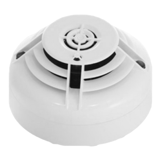
FOR MODEL NFX-SMT2 / NFXI-SMT2
PHOTO/THERMAL FIRE SENSOR
GENERAL DESCRIPTION
Models NFX-SMT2 and NFXI-SMT2 intelligent multicriteria sensors are plug-in type
fire sensors that combine dual detection capability with addressable communications.
A photoelectronic sensing chamber detects smoke, while a thermal element provides
rate-of-rise and fixed temperature heat sensing. These sensors are designed for open
area protection and must only be connected to control panels that use a compatible
proprietary communication protocol for monitoring and control.
The NFXI-SMT2 sensor contains an isolator, if installing this version check the panel
documentation for details of how many isolators can be used on a loop.
Two LEDs on each sensor light to provide a local 360
of LEDs are dependent on panel). Remote LED indicator capability is available as an
optional accessory wired to the standard base terminals (again dependent on panel).
SPECIFICATIONS
Operating Voltage Range:
Max. Standby Current (no comm.): 200 µA @24 V and 25
(comm. LED blink enabled - 5 sec) 300 µA @24 V and 25
(Read 16 sec. LED blink 8 sec)
Max. Alarm Current (LED on):
Operating Humidity Range:
Nominal Activation Temperature:
Isolator Characteristics (NFXI Only): see S00-7300
Independently tested and certified to: EN54-7: 2000, EN54-5: 2000 Class A1R and
CEA4021 (and EN54-17: 2005 for the NFXI)
WIRING GUIDE
Refer to the installation instructions supplied with the plug-in sensor bases for wiring de-
tails. All bases are provided with terminals for power and an optional Remote Indicator.
Note 1: All wiring must conform to applicable local and national codes and regulations.
Note 2: Verify that all sensor bases are installed and that polarity of the wiring is correct
at each base.
Disconnect loop power before installing sensors. Notify proper authorities.
SENSOR INSTALLATION
1. Set the sensor address (see figure 1) by turning the two rotary switches on the
underside of the sensor, selecting a number between 01 and 159. (Note: The
number of addresses available will be dependent on panel capability, check the panel
documentation for information on this). Record the address on the label attached
to the base.
Figure 1: Rotary Address Switches
X 10
2. Insert the sensor into the base and rotate it clockwise until it locks into place.
3. After all the sensors have been installed, apply power to the system.
4. Test the sensor as described under TESTING.
5. Reset the sensor by communication command from the panel.
Tamper-Resistance.
These sensors includes a feature that, when activated, prevents removal of the sensor
from the base without the use of a tool. Refer to the installation instructions for the
sensor base for details of how to use this feature.
Dust covers help to protect units during shipping and when first installed. They
are not intended to provide complete protection against contamination therefore
sensors should be removed before construction, major re-decoration or other
dust producing work is started. Dust covers must be removed before system
can be made operational.
N200-201-00
NFX(I)-SMT2
99 g
visible sensor indication (operation
o
see S00-7300
C
o
C
o
220 µA @24 V and 25
C
o
add 50 µA for NFXI Isolated
add 3.5 mA @ 24 V and 25
C
o
10% to 93% Relative Humidity, Non-Condensing
58°C
WARNING
X 1
CAUTION
Notifier by Honeywell, 140 Waterside Road, Hamilton Industrial Park, Leicester, LE5 1TN, UK
EN54-7: 2000
0786 09
EN54-5: 2000 Class A1R
DOP-IFD142 NFX-SMT2
EN54-17: 2005 (NFXI only)
DOP-IFD143 NFXI-SMT2
Figure 2: Cleaning the Sensor
Thermistor
MAINTENANCE
Before cleaning, disable the system to prevent unwanted alarms:
1. Remove the sensor to be cleaned from the system.
2. Gently release each of the four cover removal tabs that hold the cover in place (see
figure 2) and remove the sensor cover.
3. Gently remove the thermistor air guide by pulling it straight out.
4 Vacuum the outside of the screen/chamber cover carefully without removing it.
5. Remove the screen/chamber cover assembly by pulling it straight out (take care to
avoid damaging the thermistor).
6. Use a vacuum cleaner and/or clean, compressed air to remove dust and debris from
the sensing chamber, sensing chamber cover and thermistor if required..
7. Re-install the sensing chamber cover and thermistor air guide. Arrows on the plastic
indicate the positioning when replacing the chamber cover and air guide. Gently
press home until it slips into place (take care to avoid damaging the thermistor).
8 Re-install the sensor cover. Use the cover removal tabs and LEDs to align the cover
with the sensor. Snap the cover into place.
9. When all sensors have been cleaned, restore power to the loop and test the sensor(s)
as described under TESTING.
TESTING
Sensors must be tested after installation and following periodic maintenance. Disable
the zone or system undergoing maintenance to prevent unwanted alarms.
Test the sensors as follows:
Magnet Method
1. Test the sensor by positioning the test magnet (model M02-24-optional) against
the sensor body approximately 2cm from LED 1, indicated by a mark on the sensor
cover as shown in figure 3.
2. Both LED's on the sensor should latch into alarm within 30 seconds, activating the
control panel.
Figure 3: Test Magnet Position
Smoke Method
1. Using generated smoke, or synthetic smoke aerosol from an approved manufacturer
such as No Climb Products Ltd, subject the sensor to controlled amounts of smoke
in accordance with local codes of practice and manufacturer recommendations.
2. Both LED's on the sensor should latch into alarm within 30 seconds, activating the
control panel.
Direct Heat Method (Hair dryer of 1000-1500 watts).
1. Direct the heat toward the sensor from its side. Hold the heat source about 15 cm
away to prevent damage to the cover during testing.
2. The LEDs on the sensor should light when the temperature at the sensor reaches
58°C.
3. Reset the sensor at the system control panel.
After completion of the test notify the proper authorities that the system is operational.
WARNING: LIMITATIONS OF SMOKE SENSORS
Fire sensors must be used in conjunction with compatible equipment.
Smoke sensors will not sense fires which start where smoke does not reach the sensors.
A sensor may not detect a fire developing on another level of a building.
Smoke sensors also have sensing limitations. Consideration must be made of the
environment when selecting fire sensors.
Fire sensors cannot last forever. Fire sensors contain electronic parts. Even though
sensors are made to last over 10 years, any of these parts could fail at any time.
Therefore, test your fire detection system at least semi-annually. Clean and take care
of your smoke sensors regularly. Taking care of the fire detection system you have
installed will significantly reduce your product liability risks.
Notifier Fire Systems by Honeywell
Pittway Tecnologica S.r.l.
Via Caboto 19/3, 34147 Trieste, Italy
Sensor Cover
Cover Removal Tabs
Thermistor Air Guide
Sensing Chamber Cover
and Screen
Sensing Chamber
Test Magnet
Mark on Cover
LED 1
LED 2
I56-3389-006
Werbung

Verwandte Anleitungen für Honeywell NOTIFIER NFX-SMT2


Inhaltszusammenfassung für Honeywell NOTIFIER NFX-SMT2
- Seite 1 Taking care of the fire detection system you have installed will significantly reduce your product liability risks. N200-201-00 Notifier by Honeywell, 140 Waterside Road, Hamilton Industrial Park, Leicester, LE5 1TN, UK I56-3389-006...
- Seite 2 EN54-7: 2000 0786 09 Notifier Fire Systems by Honeywell NFX(I)-SMT2 EN54-5: 2000 Class A1R Pittway Tecnologica S.r.l. DOP-IFD142 NFX-SMT2 EN54-17: 2005 (NFXI only) Via Caboto 19/3, 34147 Trieste, Italy DOP-IFD143 NFXI-SMT2 Figura 2: Pulizia del sensore 102 mm Coperchio del...
- Seite 3 Un mantenimiento correcto del sistema de detección de incendio reducirá significativamente los riesgos en cuanto a su responsabilidad con el producto. N200-201-00 Honeywell Life Safety Iberia, S.L. C/ Pau Vila, 15-19, 08911 Badalona (Barcelona) Espana I56-3389-006...
- Seite 4 EN54-7: 2000 0786 09 Notifier Fire Systems by Honeywell NFX(I)-SMT2 EN54-5: 2000 Class A1R Pittway Tecnologica S.r.l. DOP-IFD142 NFX-SMT2 EN54-17: 2005 (NFXI only) Via Caboto 19/3, 34147 Trieste, Italy DOP-IFD143 NFXI-SMT2 102 mm B501AP 99 g INSTALLATIONS- UND WARTUNGSANLEITUNG FÜR...