Inhaltsverzeichnis
Werbung
Quicklinks
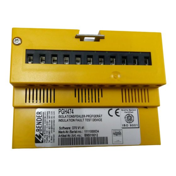
PGH474 / PGH474E
Prüfstrom-Generator
Bestimmungsgemäße Verwendung
Der Prüfstrom-Generator PGH474(E) wird innerhalb einer Einrich-
tung zur Isolationsfehlersuche eingesetzt, die zur Lokalisierung
von Isolationsfehlern in IT-Systemen medizinisch genutzter Räu-
me dient. Aufgaben des PGH474(E):
Erzeugung des Prüfstromes
Begrenzung des Prüfstromes auf 1 mA
Synchronisation mit Isolationsfehlersuchgeräten EDS461/
491
Steuerung der Isolationsfehlersuche bei Systemen ohne
Melde- und Bedientableau TM... oder Melde- und Prüfkom-
bination MK...
Synchronisierung und Steuerung erfolgt über die RS-485-Schnitt-
stelle (BMS-Bus). Die Ausführung PGH474E wird benötigt, wenn
mehr als neun Prüfstrom-Generatoren an den BMS-Bus ange-
schlossen werden.
Sicherheitshinweise allgemein
Montage, Anschluss und Inbetriebnahme nur durch Elektrofach-
kraft! Beachten Sie unbedingt:
die bestehenden Sicherheitsvorschriften und
das beiliegende Blatt „Wichtige sicherheitstechnische Hin-
weise für Bender-Produkte".
Funktionsbeschreibung
Die Isolationsfehlersuche wird abhängig vom angeschlossenen
Steuereingang entweder als permanente Isolationsfehlersuche
oder als einmaliger Durchlauf gestartet. Bei aktiviertem Prüfstrom
zeigen die Prüfstrom-LEDs den jeweils positiven und negativen
Prüftakt an.
Der Prüfstrom-Generator PGH474(E) erzeugt (bei vorhandenem
Isolationsfehler) in einem IT-System ein definiertes Prüfstromsig-
nal. Der Prüfstrom ist begrenzt auf max. 1 mA und muss per DIP-
Schalter auf ein- bzw. dreiphasige Netze angepasst werden. Das
Prüfstromsignal wird von den im Fehlerstromkreis liegenden
Messstromwandlern erfasst und die fehlerbehafteten Abgänge
werden von den Isolationsfehlersuchgeräten EDS461/491 ange-
zeigt.
TBP108010deen / 11.2012
Locating current injector
Intended use
The locating current injector PGH474(E) is used in insulation fault
location systems intended for the localisation of insulation faults
in IT systems in medical locations. Tasks of the PGH474(E):
Locating current generation
Limitation of the locating current to 1 mA
Synchronisation with insulation fault locators EDS461/491
Control of insulation fault location in systems without TM
alarm indicator and operator panels or MK.. alarm and test
combinations.
Synchronisation and controlling is carried out via the RS-485 in-
terface (BMS bus). Version PGH474E is required if more than nine
locating current injectors are connected to the BMS bus.
General safety information
Installation, connection and commissioning shall only be carried
out by electrically skilled persons! Particular attention shall be
paid to:
the current safety regulations and
the enclosed sheet "Important safety instructions for Bender
products".
Function
Depending on the connected input, you can either start a perma-
nent insulation fault location process or one pass only. With the
locating current activated, the locating current LEDs indicate the
positive or negative test cycle in each case.
In an IT system the locating current injector PGH474(E) generates
(in case of an occurring insulation fault) a defined locating current
signal. The locating current is limited to max. 1 mA and has to be
adapted to single and three phase systems using a DIP switch.
The locating current signal is detected by the measuring current
transformers located in fault current circuit and the faulty subcir-
cuits will be indicated by the EDS461/491 insulation fault loca-
tors.
1
Werbung
Inhaltsverzeichnis

Inhaltszusammenfassung für Bender PGH474
- Seite 1 Bestimmungsgemäße Verwendung Intended use Der Prüfstrom-Generator PGH474(E) wird innerhalb einer Einrich- The locating current injector PGH474(E) is used in insulation fault tung zur Isolationsfehlersuche eingesetzt, die zur Lokalisierung location systems intended for the localisation of insulation faults von Isolationsfehlern in IT-Systemen medizinisch genutzter Räu- in IT systems in medical locations.
-
Seite 2: Bedienelemente
PGH474 / PGH474E Bedienelemente Operating elements Dargestellt ist das PGH474. Beim PGH474E haben die DIP-Schal- The PGH474 is illustrated below. The functions of the DIP switch- ter abweichende Funktionen. es of PGH474E are different from the standard device. Legende: Legend: LED „ON“... -
Seite 3: Anschluss
PGH474 / PGH474E Anschluss Connection An die Klemmen A, B, GND, IN1, IN2 und IN3 dürfen Only permanently installed equipment providing at nur fest installierte Geräte, die mindestens die Anfor- least overvoltage category II (300 V) may be connect- derungen der Überspannungskategorie CAT II (300V) ed to the terminals A, B, GND, IN1, IN2 and IN3. - Seite 4 In this case, only the locating cur- strom-Generator PGH474 einen Prüftakt ausgeben, in des- rent injector PGH474 is allowed to output a test cycle in the sen IT-System der Isolationsfehler aufgetreten ist. IT system of which an insulation fault has occurred. Note:...
- Seite 5 Das PGH474 wird in Kombination mit einem EDS461/491 The PGH474 is used in conjunction with an EDS461/491. The eingesetzt. Auf dem BMS-Bus ist das PGH474 Master. Es PGH474 is the master on the BMS bus. It controls insulation steuert die Isolationsfehlersuche. fault location.
-
Seite 6: Bedienung
PGH474 / PGH474E Einstellungen PGH474E Settings PGH474E S L AV E A D D R E S S + 1 2 0 S L AV E A D D R E S S + 1 2 0 1 m A... -
Seite 7: Technische Daten
Messages on the BMS bus Alarmmeldungen können auf anderen Bender-Geräten (z.B. Mel- Alarm messages can also be displayed on other Bender devices de- und Bedientableau TM..., Melde- und Prüfkombination MK...) such as TM... alarm indicator and operator panels, MK... alarm in- dargestellt werden. -
Seite 8: Ordering Information
Genehmigung des Herausgebers. only with permission of the publisher. Änderungen vorbehalten! Subject to change! © © Bender GmbH & Co. KG Bender GmbH & Co. KG Bender GmbH & Co. KG Tel.: +49 6401 807-0 E-Mail: info@bender-de.com •...


