Werbung
Quicklinks
Werbung

Verwandte Anleitungen für HEIDENHAIN LB 383


Inhaltszusammenfassung für HEIDENHAIN LB 383
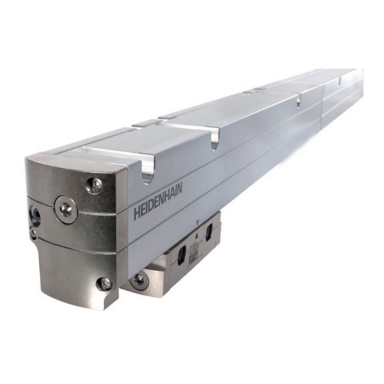
- Seite 1 Mounting Instructions Montageanleitung LB 383 LB 383 C multi-section mehrteilig 07/2022...
- Seite 2 Contents Standard version Inhalt Standardausführung Dimensions in mm Mirror-image version Maße in mm Spiegelbildliche Ausführung Page Seite Warnings Warnhinweise Items supplied/Parts kit Lieferumfang Teilesatz Mounting information Hinweise zur Montage 12 Mounting options and mounting tolerances 12 Montagemöglichkeiten und Anbautoleranzen 15 Fastening the housing sections 15 Befestigung der Gehäuseteilstücke 19 Inserting the bearing strips 19 Laufbänder einziehen...
- Seite 3 Warnings Warnhinweise Note: Mounting and commissioning is to be conducted by a qualified specialist under compliance with local safety regulations. „ Do not engage or disengage any connections while under power. „ The system must be disconnected from power. „ Scanning unit must first be installed before it is put into operation.
- Seite 4 Items supplied/Parts kit Lieferumfang Teilesatz Mounting Instructions Montageanleitung Small parts set Kleinteilesatz Scale tape (measuring length ML) LB 383 Maßband (Messlänge ML) ID label Typenschild Sealing lip Dichtlippe Housing end section (mirror-image version also available) Gehäuseendstück (auch spiegelbildlich lieferbar) Housing end section with scale-tape tensioning device and scale-tape clamp (mirror-image version also available) Gehäuseendstück mit Maßband-Spannvorrichtung und...
- Seite 5 Items supplied/Scale-tape housing, scanning unit Lieferumfang Maßbandgehäuse, Abtasteinheit Scale-tape housing Maßbandgehäuse Insertion aid Einführhilfe Scanning unit Abtasteinheit Shipping brace Transportsicherung Order separately: Mounting aid for aligning the Separat bestellen: fastening element for the scanning head. Montagehilfe zur Ausrichtung Clamp des Befestigungselementes Klemmstück für die Abtasteinheit Lubrication device...
- Seite 6 Schild für Korrekturwerte Slider Schieber Grease for sealing lips and housing-section seal Fett für Dichtlippen und Dichtung Gehäuse-Teilstücke Scale-tape puller RM (1x) Maßband-Einziehwerkzeug Reference mark selector plate Referenzmarkenblende R (1x) MW (1x) Reference mark label Referenzmarkenschild only LB 383 nur LB 383...
- Seite 7 Mounting information Hinweise zur Montage Keep the transport protection, small parts set and packaging components for encoder disassembly. Für die Demontage des Messgerätes Transportschutz, Kleinteilesatz und Verpackungsteile aufbewahren. Caution: Be sure that no contamination enters the encoder while you are mounting the device. Mount with sealing lips facing away from possible sources of contamination.
- Seite 8 Climping sleeve for ML > 30 040 mm Klemmstück für ML > 30 040 mm To ensure that thermal changes of the machine are transferred to the scale tape (M), an additional clamping section must be mounted every 10 000 mm (33 ft) starting with a measuring length of >...
- Seite 9 If there is significant danger of contamination, fit a protective cover over the encoder with a seal between it and the mounting surface. Bei größerer Verschmutzungsgefahr empfiehlt sich eine zusätzliche Abdeckung mit Dichtung zwischen Anbaufläche und Abdeckung. Choose a mounting attitude such that the maximum traverse range is within the measuring length ML of the encoder.
- Seite 10 Connection of compressed air. (DA 400 compressed air unit as accessory). Anschluss von Druckluft. (Druckluftanlage DA 400 als Zubehör). Compressed-air connection possible at either end Druckluftanschluss beidseitig möglich Preferred for use Bevorzugt zu verwenden Please order HEIDENHAIN accessories separately HEIDENHAIN-Zubehör separat bestellen...
- Seite 11 Reference Mark Position LB 383 Referenzmarken-Lage LB 383 A reference mark can be selected at any mounting hole and at intervals of n x 50 mm from it. An jedem Befestigungsloch und davon im Abstand von n x 50 mm kann eine Referenzmarke ausgewählt werden.
- Seite 12 Mounting options and mounting tolerances ISO 7092-6 (ISO 7090-5) Montagemöglichkeiten und Anbautoleranzen ISO 4762-M6 (ISO 4762-M5) ISO 4762-M6 ,, = Mounting options Montagemöglichkeiten 0.1 A 10 ± 0.3 Required mating dimensions Kundenseitige Anschlussmaße Compressed air inlet Druckluftanschluss Pay attention to the mating surface Auf Anlagefläche achten ISO 4032-M6...
- Seite 13 Required mating dimensions Kundenseitige Anschlussmaße Machine guideway Maschinenführung Reference mark position LB 383 Referenzmarken-Lage LB 383 Reference mark position LB 383C Referenzmarken-Lage LB 383C (n x 200) ± 1 80 ± 0.15 90 ± 0.15 m x 200 ± 0.15 0.3 F...
- Seite 14 n x 200 ± 1 n = (ML - 40) / 200 m x (10 000 + 200) fixing m = 0, 1, ... Fixierung = 4000 fixing 5 x 2000 = 10 000 5 x 2000 = 10 000 Fixierung 2000 2000...
- Seite 15 Fastening the housing sections Befestigung der Gehäuseteilstücke Ensure that the mounting surfaces is free of paint, dust or grease! Auf lack-, staub- und fettfreie Montageflächen achten! > 4 0 > 2 5 > 8 0 Remove housing end cap from end section (E1). Remove protective film and protective cap.
- Seite 16 Attach the threaded mounting holes to the machine. F = Machine guideway 0 . 3 Befestigungsgewinde an der Maschine anbringen. F = Maschinenführung M6 (M5) Screw on housing end section and align it to the machine guideway F . Gehäuseendstück anschrauben und zur Maschinenführung F ausrichten.
- Seite 17 Maintain correct gap between housing sections. Recommendation: Use a mounting gauge (to be ordered separately). *) Within the specified hole tolerances, a tolerance of ±1 mm is also permissible. Zwischen den Gehäuseteilstücken Spalt einhalten. Empfehlung: Montagelehre (separat bestellen) verwenden. *) Innerhalb der vorgegebenen Bohrungstoleranzen ±1 mm Toleranz zulässig ID 772141-11 2 mm...
- Seite 18 Remove the housing end cap from (E2). Remove the tensioning device. Slide out stop plate (KA). Remove protective film and protective cap. Gehäusedeckel von (E2) entfernen. Spanneinrichtung (SE) entnehmen. Anschlagplatte (KA) herausschieben. Schutzfolie und Schutzkappe entfernen. Slide housing end section (E2) onto the housing middle section, align and fasten.
- Seite 19 Inserting the bearing strips Laufbänder einziehen The bearing strips can be pulled in using the puller (EW). Place the hooks of the puller in the required position. Insert the puller (EW) into the scale housing. Pay attention to the correct positions of the stops and the positions of the hooks 1, , ...
- Seite 20 Pull the end of the bearing strip out of the cassette. Den Anfang des Laufbandes aus der Laufbandkassette ziehen. Hook the bearing strip onto the catch such that beveled corners point upwards. Ensure that the bearing strip is seated properly in the groove. Feed the bearing strip into the housing.
- Seite 21 If the encoder is removed from the machine, the bearing strips can be repacked in the cassettes. Video on packing the bearing strip: https://www.heidenhain.com/products/linear-encoders/sealed/lc-200/installation-lc-201-bearing-strip Die Laufbänder können bei der Demontage des Messgerätes mit den Laufbandkassetten wieder verpackt werden. Video über das Verpacken des Laufbandes:...
- Seite 22 Bei Verschmutzung die Teilung des Maßbandes mit fusselfreiem Tuch „ und destilliertem Spiritus oder Isopropylalkohol reinigen. Write down the shortening factor V and the scale-tape serial number on the supplied label. HEIDENHAIN Verkürzungsfaktor V und Seriennummer des Maßbandes auf dem www.heidenhain.de mitgeliefertem Schild notieren.
- Seite 23 Loosen screw by approx. 2 rotations. Pull out the pressure piece as far as possible. *) ML > 30040 mm Schraube ca. 2 Umdrehungen herausdrehen. Druckstück bis zum Anschlag rausziehen. SW 2.5 Insert the scale tape (M) at the housing end section (E1) and slide it in about 200 mm.
- Seite 24 Insert the scale tape puller (MW) at the mark. The scale tape puller (MW) automatically snaps into the scale tape during insertion. Pull scale tape through until it engages the fastening hook (KM). Remove the scale-tape puller. Maßband-Einziehwerkzeug (MW) an der Markierung einsetzen. Während des Einziehvorgangs rastet das Einziehwerkzeug (MW) selbstständig im Maßband ein.
- Seite 25 Insert the tensioning device. Loosen hook scree (SH) until scale tape engages. Retighten the hook screw. 1.2+/-0.15 Nm Spanneinrichtung einlegen. Hakenschraube (SH) lösen, bis Maßband einrastet. Hakenschraube wieder festziehen. After the hook screw (SH) has been tightened, the scale tape is now tensioned at the correct length.
- Seite 26 Pulling in the sealing lips Dichtlippen einziehen Sealing lips are mounted preloaded. Mark the length (L) on the sealing lip! Dichtlippen werden vorgespannt montiert. Länge (L) auf Dichtlippe markieren! L = (ML + 226) x 0.98 While pulling them in, slightly lubricate the sealing lips on the inside with sealing lip grease (FT) over the entire length.
- Seite 27 Pull through both sealing lips, and push on the clamping sleeve until it is flush. If necessary, loosen the sealing lips with your fingers while pulling them in. Beide Dichtlippen einziehen und Klemmhülse (KH) bündig aufschieben. Bei Schwergängigkeit die Dichtlippen während des Einziehens mit den Fingern auflockern.
- Seite 28 At the other end, pull out the sealing lips so that the marking protrudes >10 mm. Slide the clamping sleeve (KH) up into the profile and push it in as far as it will go. Note: The Sealing lip, sleeve edge and extrusion must be flush. The sealing lip must be under tension! Dichtlippen am anderen Ende so weit herausziehen, dass Markierung >10 mm übersteht.
- Seite 29 Using the slider (S), orient the sealing lips outward over the entire length. Note: For the LB 383, pay attention to the reference mark selector plate. Dichtlippen über die gesamte Länge mit dem Schieber (S) aufstellen. Achtung: bei LB 383 auf Referenzmarkenblende achten.
- Seite 30 Fastening the stop piece and the housing cover (end piece E2) Anschlag und Gehäusedeckel befestigen (Endstück E2) Slide stop plate (KA) into housing end section (E2). Fasten the housing end cap with 3 screws. Caution: Pay attention to the seal. The sealing lips should fit closely. = 1 Nm Anschlagplatte (KA) in Gehäuseendstück (E2) bündig einschieben.
- Seite 31 Mounting the scanning unit Abtasteinheit montieren Caution: To avoid damage to the encoder, use the included shipping brace to secure the scanning unit during mounting and moving. Achtung: Um das Messgerät nicht zu beschädigen, sollte die Abtasteinheit bei Montage und beim Verfahren mit der Transportsicherung aus dem Lieferumfang gesichert werden.
- Seite 32 Slide the scanning unit from the insertion aid (EH) into the scale housing (E1) and, together with the first shipping brace, slide it into the housing until the second shipping brace can be clicked in. Abtasteinheit aus Einführhilfe (EH) ins Maßstabprofil (E1) einschieben und zusammen mit der ersten Transportsicherung soweit in Gehäuse einschieben, bis die zweite Transportsicherung eingeklickt werden kann.
- Seite 33 Check the mounting tolerances over the entire measuring length. Anbautoleranzen über die gesamte Messlänge überprüfen. 0 . 3 Cable connection usable at either end. For tight spaces, use the mounting wrench (MS)! Caution: The scanning unit may only be connected when properly installed and when the scale tape has been pulled in correctly.
- Seite 34 Fastening the housing cover (end piece E1) Gehäusedeckel befestigen (Endstück E1) Fasten the housing end cap with 3 screws. Caution: Pay attention to the seal. The sealing lips should fit closely. Gehäusedeckel mit 3 Schrauben befestigen. Achtung: Auf Dichtung achten. Die Dichtlippen sollen gut anliegen. = 1 Nm...
- Seite 35 ID 689924-01 M6x12 M6, SW6: ID 689924-02 Connect the encoder to a HEIDENHAIN PWM 21 phase meter or other suitable subsequent electronics and check for proper function over the entire range of traverse. Attach ID label (T2). Messgerät an einem HEIDENHAIN-Prüfgerät, z. B. PWM 21 oder einer geeigneten Folge-Elektronik anschließen und die...
- Seite 36 Linear error compensation Lineare Fehlerkorrektur A linear error compensation of up to ±35 µm/m can be applied to the entire measuring length with the tape tensioning device. Eine lineare Fehlerkorrektur über die gesamte Messlänge kann bis ±35 µm/m über die Spanneinrichtung des Maßbandes erfolgen. Set up a comparator system (such as a laser interferometer) in the Laser workpiece plane and measure the machine.
- Seite 37 Tensioning the scale tape Maßband spannen Remove the screw plug (SW5) *) Release clamping screws (KS) by about 2 revolutions. *) ML > 30040 mm (Screw is flush with fixing component) Verschlussschraube entfernen (SW5) *) Klemmschrauben (KS) ca. 2 Umdrehungen lösen. (Schraube mit Befestigungsteil bündig) SW 2.5...
- Seite 38 Move the scanning unit as far as possible within the permitted measuring length toward the end section. Measure the distance X and compare it with the value X from the calibration of the machine. Abtasteinheit innerhalb der zulässigen Messlänge soweit wie möglich in Richtung Endstück fahren. Abstand X messen und mit dem Wert X Vermessung der Maschine vergleichen.
- Seite 39 Correct scale tape tenstion until X Maßbandspannung korrigieren bis X Screw in the screw plug. Tighten the clamping screw (K Verschlussschraube einschrauben. = 2 Nm Klemmschraube (K ) anziehen. = 1.5 Nm Tighten the clamping screw (K Klemmschraube (K ) anziehen. *) ML >...
- Seite 40 Hinweise – spiegelbildliche Version The following section describes how to mount the scale tape on the mirror-image version of the LB 383/383C. For a description of how to fasten the housing sections, insert the bearing strips and sealing lips, install the tensioning device, mount the scanning unit and perform the final steps, as well as for linear error compensation and general information, please refer to the corresponding sections of the standard version.
- Seite 41 Mounting the scale tape – Mirror-image version Maßbandmontage – spiegelbildliche Version Insert the scale tape (M) at the housing end section (E2) and slide it in about 300 mm. The graduation must be facing downward. Pay attention to the orientation of the punched-out part. Das Maßband (M) am Gehäuseendstück (E2) ca.
- Seite 42 Hook the tensioning device (SE) into the scale tape (M) and push it into the end piece (E2) until it stops. Spanneinrichtung (SE) in Maßband (M) einhängen und in Endstück (E2) bis Anschlag einschieben. Loosen the hook screw (SH) until the scale tape engages the fastening hook (KM).
- Seite 43 DR. JOHANNES HEIDENHAIN GmbH Dr.-Johannes-Heidenhain-Straße 5 83301 Traunreut, Germany { +49 8669 31-0 | +49 8669 32-5061 E-mail: info@heidenhain.de Technical support | +49 8669 32-1000 Measuring systems { +49 8669 31-3104 E-mail: service.ms-support@heidenhain.de NC support { +49 8669 31-3101 E-mail: service.nc-support@heidenhain.de...