Inhaltsverzeichnis
Werbung
Verfügbare Sprachen
Verfügbare Sprachen
Quicklinks
Werbung
Inhaltsverzeichnis
Fehlerbehebung

Verwandte Anleitungen für Modster 285902


Inhaltszusammenfassung für Modster 285902
- Seite 1 1300mm Bigfoot Operating Manual...
-
Seite 2: Sicherheits- Und Warnhinweise
Warnung: Dieses Handbuch enthält wichtige Informationen, mit denen Sie Ihr Modellflugzeug zuverlässig und sicher warten und betreiben können. Bitte lesen Sie die Anweisungen und Warnungen vor der Montage, Einrichtung oder Verwendung sorgfältig durch. Da es sich bei diesem Modellflugzeug um ein hoch entwickeltes Hobbyprodukt handelt, muss es unter Berücksichtigung der Sicherheit und des gesunden Menschenverstandes geflogen werden. -
Seite 3: Inhaltsverzeichnis
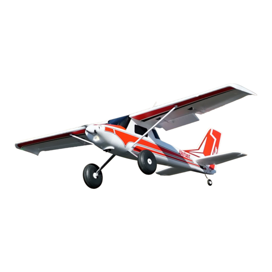
Einleitung Als Allzweck-Flugzeug verfügt die Arrows Hobby Bigfoot über erstaunliche Funktionen aus einer großen Bandbreite innerhalb der Luftfahrt. In Sachen Flugeigenschaften ist Bigfoot einfach zu handhaben wie ein Trainer. Die Maschine hat Eigenschaften eines Buschflugzeugs mit übergroßen Klappen und bietet unglaublich gutmütige Langsamflugeigenschaften. -
Seite 4: Bauanleitung
Bauanleitung Fahrwerk-Installation 1. Richten Sie bei umgedrehtem Rumpf das Fahrwerk und die Kunststoffverkleidung auf den Schlitz im Rumpf aus. HKM3.0*10mm 2. Befestigen Sie das Fahrwerk mit den mitgelieferten Schrauben. Höhen- und Seitenleitwerk-Installation 1. Richten Sie das Höhenleitwerk auf dem Rumpf aus. - Seite 5 Bauanleitung 2. Kleben Sie das Seitenleitwerk mit dem mitgelieferten doppelseitigen Klebeband wie in der Abbildung gezeigt auf den Rumpf. HKM3.0*26mm 3. Befestigen Sie bei umgedrehtem Rumpf das angelegte Höhen- und Seitenleitwerk mit den mitgelieferten HKM 3.0 x 26 mm-Schrauben am Rumpf. Befestigen Sie die Ruderstange mit den KA 2.0 x 12 mm- Schrauben.
- Seite 6 Bauanleitung HKM3.0*26mm 2. Schließen Sie die Klappenservos und dann die Querruder- servos mit den mitgelieferten Y-Kabeln an. Bringen Sie den Hauptflügel mit den mitgelieferten Schrauben an und schließen Sie den LED-Controller an den Empfänger an. 3. Installieren Sie die Flügelstreben am Rumpf und sichern Sie sie mit den mitgelieferten Klammern.
-
Seite 7: Propeller-Installation
Bauanleitung Schubstangen-Installation 1.Verbinden Sie die Schubstange des Höhenleitwerks wie gezeigt mit dem Ruderhorn. 2.Verbinden Sie die Schubstange des Seitenleitwerks mit dem Ruderhorn. Propeller-Installation 1.Montieren Sie den Spinner und den Propeller wie gezeigt. Hinweis: Der Motor sollte sich im Uhrzeigersinn drehen, wenn Sie das Flugzeug von hinten betrachten. -
Seite 8: Akku-Installation
Akku-Installation 1. Entfernen Sie die Verschlussklappe des Akkus. 2. Entfernen Sie das Klettband vom Rumpf. Bringen Sie die Schleifen-Seite am Akku an. 3. Setzen Sie den Akku in den Rumpf ein und sichern Sie sie mit den vorinstallierten Bändern. Hinweis: Das Gewicht jedes Akkus kann aufgrund unter- schiedlicher Herstellungstechniken variieren. -
Seite 9: Die Empfohlene Einstellung Für Den Ruderausschlag Lautet Wie Folgt (Servo-Wegbegrenzung)
Vor ug-Check Sender- und Modell-Einstellung Stellen Sie nach der Montage und vor Ihrem ersten Flug sicher, dass alle Bedienoberflächen korrekt (wie auf dem Diagram unten angegeben) auf Ihren Sender reagieren. Höhenruder Querruder Seitenruder Ruderausschlag Die empfohlene Einstellung für den Ruderausschlag lautet wie folgt (Servo-Wegbegrenzung): Tipp: Der Jungfernflug sollte immer mit kleinem Ausschlag geflogen werden. -
Seite 10: Ruderhorn Und Servoarm-Einstellungen
Ruderhorn und Servoarm-Einstellungen Mehr Ruderausschlag Horn Arms 1. Die Tabelle zeigt die Werkseinstellungen für die Ruderhörner und Servo-Arme. Fliegen Sie das Flug- zeug in den Werkseinstellungen, bevor Sie Änderun- gen vornehmen. Weniger Ruderausschlag 2. Nach dem Fliegen können Sie die Verbindung anpassen. -
Seite 11: Vor Dem Flug
Vor dem Flug Schalten Sie Ihren Sender immer zuerst ein. Installieren Sie einen vollständig geladenen Akku im Akkufach und schließen Sie ihn an den Regler an. Stellen Sie bei diesem Vorgang sicher, dass die Gasfunktion aktiviert ist und der Gashebel in seiner niedrigsten Position gesichert ist. -
Seite 12: Problembehebung
Problembehebung Problem Möglicher Grund Lösung Gashebel und -trimmer auf niedrigsten Wert stellen. Flugzeug reagiert nicht auf Drehzahlregler (ESC) ausgeschaltet. Gashebel, aber auf andere Gaskanal seitenverkehrt eingestellt. Befehle. Gaskanal am Sender umdrehen. Spinner, Propeller, Motor o. Defekte Teile ersetzen. Flugzeug reagiert nicht auf Teile an Propeller(-Adapter) und Spinner festziehen. -
Seite 13: Gewärhleistungsausschluss
Gewärhleistungsausschluss - Dieses Modell darf nicht von Kindern unter 14 Jahren benutzt werden. - Es enthält kleine Teile, die verschluckt werden können - Halten Sie Hände, Gesicht, Haare und lose Kleidung vom Propeller fern - Greifen Sie nicht in rotierende Teile - Ziehen Sie nach dem Flug immer den Akkustecker ab und entfernen Sie den Akku - Fliegen Sie nur dort, wo es sicher ist und wo Sie keine Dritten gefährden - Bewahren Sie die Betriebsanleitung gut auf und lesen sie vor der Benutzung des Modells sorgfältig durch...