Anmelden
Hochladen
Anleitungen
Marken
Austroflamm Anleitungen
Kamine
74 S
Austroflamm 74 S Handbücher
Anleitungen und Benutzerhandbücher für Austroflamm 74 S. Wir haben
1
Austroflamm 74 S Anleitung zum kostenlosen PDF-Download zur Verfügung: Montagehandbuch
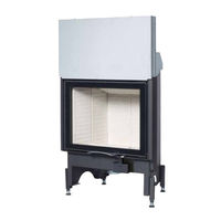
Austroflamm 74 S Montagehandbuch (120 Seiten)
Kamineinsätze / Schieb
Marke:
Austroflamm
| Kategorie:
Kamine
| Dateigröße: 7.45 MB
Inhaltsverzeichnis
Deutsch
4
Inhaltsverzeichnis
4
1 Allgemeine Informationen
5
Zu Beachtende Vorschriften / Grundsätzliche Anforderungen
5
Kontrollen vor Montage
5
Gerätebeschreibung
5
Tragehilfe
8
Aufstellen des Heizkamineinsatzes
8
Geräteplatzierung
9
Abgasrohranschluss
9
Transportsicherung (Modelle mit Schiebetür)
9
Demontage Keramottsicherung und Einbau der Umlenkplatte (65X - 75X; 55X55X)
11
Einbau der Umlenkplatten (alle anderen Modelle)
11
2 Anforderungen an den Aufstellungsraum
13
Verbrennungsluftversorgung
13
Verbrennungsluftversorgung aus dem Raum
13
Verbrennungsluftversorgung über Direkte Leitung
14
Verbrennungsluftleitung
14
Anforderungen an den Schornstein
14
Verbindungsstücke / Abgasrohr
14
3 Technische Daten
15
4 Daten für die Schornstein-/Kaminbemessung
18
Minimalquerschnitte Schornstein / Verbrennungsluftleitung
18
5 Wärmedämmstoffe
19
6 Einbauvorschriften
20
Aufbau vor oder Neben einer zu Schützenden Wand
20
Konvektionsraum
21
Seitliche und Rückwärtige Wärmedämmschichten
21
Schutz des Aufstellbodens
21
Dehnungsfugen
21
Verkleidung
21
Kaminschürzen
21
Zierbalken
22
Konvektionsführung
22
Decke über dem Kamineinsatz
22
Fußboden vor dem Kamineinsatz
22
Brandschutz IM Strahlungsbereich
22
Brandschutz Außerhalb des Strahlungsbereiches
23
Elektrische Leitungen
23
Raumluftunabhängig Geprüfte Kamineinsätze
23
7 Information zur Wartung / Reparatur
23
Türausbau Flach-Schiebetürgeräte 2.0 (65X bis 75X / 80X64 / 97X45/74 / 120 X 45)
23
Türausbau Eck-Schiebetürgeräte
24
(55X55X51 / 55X55X57 / 63X40X42 / 63X40X51 / 69X49X57 / 89X49X45 / 89X49X57)
24
Türausbau bei 48X S3 / 75X35X45 S3 / 64X33X51 S3 / VUUR DRIE 60 & 80
25
Platzierung der Typenschilder
26
Feuerraumauskleidung
27
8 Anschluss an Keramische Züge
29
Heizkamin mit Keramischem Zug
30
Anschluss an Metallische Nachheizflächen
30
English
32
1 General Information
33
Regulations to be Observed / Basic Requirements
33
Pre-Installation Inspections
33
Description of the Appliances
33
Carrying Aid
36
Setting up the Fireplace Insert
36
Positioning the Appliance
37
Connecting the Flue Pipe
37
Transport Lock (Models with Sliding Door)
37
Dismantling the Keramott Protection and Fitting the Deflector Plate
39
65X - 75X; 55X55X)
39
Fitting the Deflector Plates (All Other Models)
39
2 Demands on the Installation Space
41
Combustion Air Supply
41
Combustion Air Supply from the Room
41
Combustion Air Supply Via a Direct Duct
42
Combustion Air Duct
42
Demands on the Chimney
42
Connecting Pieces / Flue Pipe
42
3 Technical Data
43
4 Data for Designing the Chimney / Fireplace
46
Minimum Cross Sections of Chimney / Combustion Air Duct
46
5 Thermal Insulation Materials
47
6 Installation Instructions
48
Installation in Front Of, or Next To, a Wall Requiring Extra Protection
48
Convection Space
49
Lateral and Rear Thermal Insulation Layers
49
Protecting the Installation Floor
49
Expansion Joints
49
Cladding
49
Fireplace Apron
49
Ornamental Beam
50
Convection Air Duct
50
Ceiling above the Fireplace Insert
50
Flooring in Front of the Fireplace Insert
50
Fire Protection in the Radiation Area
50
Fire Protection Outside the Radiation Area
51
Electrical Wiring
51
Fireplace Inserts Approved for Balanced Flue Operation
51
7 Information on Maintenance / Repair
51
Removing the Door on Appliances with a Flat Sliding Door 2.0
51
(65X to 75X / 80X64 / 97X45/74 / 120 X 45)
51
Removing the Door on Appliances with a Corner Sliding Door
52
(55X55X51 / 55X55X57 / 63X40X42 / 63X40X51 / 69X49X57 / 89X49X45 / 89X49X57)
52
Removing the Door on 48X S3 / 75X35X45 S3 / 64X33X51 S3 / VUUR DRIE 60 & 80
53
Placement of the Type Plates
54
Firebox Lining
55
8 Connecting to Ceramic Flues
57
Fireplace Heater with a Ceramic Flue
58
Connecting to Metallic Secondary Heating Surfaces
58
Italiano
60
1 Informazioni Generali
61
Norme da Osservare / Requisiti Basilari
61
Controlli Prima del Montaggio
61
Descrizione Degli Apparecchi
61
Supporto Per Il Trasporto
64
Montaggio Dell'inserto Per Camino
64
Collocamento Dei Dispositivi
65
Uscita Fumi
65
Fissaggio Per Il Trasporto (Modelli con Sportello Scorrevole)
65
Smontaggio Della Protezione in Keramott E Montaggio del Deflettore (65X - 75X; 55X55X)
67
Montaggio Dei Deflettori (Tutti Gli Altri Modelli)
67
2 Requisiti del Locale DI Installazione
69
Alimentazione DI Aria Comburente
69
Alimentazione DI Aria Comburente Dal Locale
69
Alimentazione Dell'aria Comburente Attraverso un Condotto Diretto
70
Condotto Dell'aria Comburente
70
Requisiti Della Canna Fumaria
70
Raccordi / Tubo Uscita Fumi
70
3 Dati Tecnici
71
4 Dati Per la Misurazione Della Canna Fumaria/Del Camino
74
Sezioni Trasversali Minime Della Canna Fumaria / Condotto Dell'aria Comburente
74
5 Prodotti Per L'isolamento Termico
75
6 Prescrizioni DI Montaggio
76
Installazione Davanti O Accanto a una Parete Che Necessita DI Protezione
76
Zona DI Convezione
77
Strati D'isolamento Termico Laterali E Posteriori
77
Protezione del Pavimento DI Posa
77
Giunti DI Dilatazione
77
Rivestimento
77
Cappe del Camino
77
Trave Ornamentale
78
Flusso Dell'aria Convettiva
78
Soffitto Sopra All'inserto del Camino
78
Pavimento Davanti All'inserto del Camino
78
Protezione Antincendio Nell'area D'irraggiamento
78
Protezione Antincendio al DI Fuori Dell'area D'irraggiamento
79
Cavi Elettrici
79
Inserti DI Camini Approvati Per Funzionamento Indipendente Dall'aria Ambiente
79
7 Informazione Su Manutenzione / Riparazione
79
Smontaggio Sportello DI un Dispositivo con Sportello Scorrevole Piatto 2.0
79
(65X Fino a 75X / 80X64 / 97X45/74 / 120 X 45)
79
Smontaggio Sportello DI un Dispositivo con Sportello Scorrevole Ad Angolo
80
(55X55X51 / 55X55X57 / 63X40X42 / 63X40X51 / 69X49X57 / 89X49X45 / 89X49X57)
80
Smontaggio Sportello Nei Modelli 48X S3 / 75X35X45 S3 / 64X33X51 S3 / VUUR DRIE 60
81
Collocamento Delle Targhette Identificative
82
Rivestimento Interno del Focolare
83
8 Collegamento Ai Condotti Dei Fumi in Ceramica
84
Camino con Condotto Dei Fumi in Ceramica
86
Collegamento alle Estensioni Delle Superfici Riscaldanti in Metallo
86
Français
88
1 Informations Générales
89
Prescriptions à Respecter / Exigences de Base
89
Contrôles Avant Montage
89
Description de L'appareil
89
Aide au Transport
92
Installation du Foyer
92
Mise en Place de L'appareil
93
Raccordement du Conduit de Fumée
93
Sécurité de Transport (Modèles Avec Porte Relevable)
93
Démontage de la Protection de la Keramott et Installation des Plaques Déflectrices
95
(65X - 75X; 55X55X)
95
Installation des Plaques Déflectrices (Tous les Autres Modèles)
95
2 Exigences Concernant le Lieu D'implantation
97
Alimentation en Air de Combustion
97
Approvisionnement en Air de Combustion Par la Pièce
97
Approvisionnement en Air de Combustion Par Conduite Directe
98
Conduits D'air de Combustion
98
Exigences Concernant le Conduit de Cheminée
98
Éléments de Raccordement / Conduit de Fumée
98
3 Données Techniques
99
4 Données Destinées au Dimensionnement du Conduit de Cheminée
102
Sections Minimales du Conduit de Cheminée / D'air de Combustion
102
5 Isolants Thermiques
103
6 Prescriptions de Montage
104
Construction Devant ou à Côté D'un Mur à Protéger
104
Espace de Convection
105
Couches D'isolation Thermique à L'arrière et Sur les Côtés
105
Protection du Sol Sous le Foyer
105
Joints de Dilatation
105
Habillage
105
Hotte
105
Poutres Décoratives
106
Circulation de L'air de Convection
106
Plafond Au-Dessus du Foyer
106
Sol Devant le Foyer
106
Protection Incendie Dans le Périmètre de Rayonnement
106
Protection Incendie en Dehors du Périmètre de Rayonnement
107
Conduites Électriques
107
Foyers Certifiés pour un Raccordement à L'air Externe
107
7 Informations Sur la Maintenance / Réparation
107
Déposer la Porte D'appareils à Porte Relevable Plane 2.0
107
(65X bis 75X / 80X64 / 97X45/74 / 120 X 45)
107
Déposer la Porte D'appareils à Porte Relevable en Angle
108
(55X55X51 / 55X55X57 / 63X40X42 / 63X40X51 / 69X49X57 / 89X49X45 / 89X49X57)
108
Déposer la Porte Sur les Modèles
109
S3 / 75X35X45 S3 / 64X33X51 S3 / VUUR DRIE 60 & 80
109
Emplacement des Plaques Signalétiques
110
Habillage du Foyer
111
8 Raccordement au Circuit Céramique
113
Foyer Avec Circuit en Céramique
114
Raccordement à des Surfaces de Chauffe Métalliques
114
Werbung
Werbung
Verwandte Produkte
Austroflamm 75S
Austroflamm 75 serie
Austroflamm 75x39 SII
Austroflamm 75x51 SII
Austroflamm 71x51 S3
Austroflamm 71x57 S3
Austroflamm 75x
Austroflamm 75x39 K 2.0
Austroflamm 75x57 K 2.0
Austroflamm 70258-1
Austroflamm Kategorien
Kamine
Pelletofen
Pelletöfen
Herde
Heizkessel
Weitere Austroflamm Anleitungen
Anmelden
Anmelden
ODER
Mit Facebook anmelden
Mit Google anmelden
Anleitung hochladen
Von PC hochladen
Von URL hochladen