Aritech ATS1840 Installation Sheet
Quicklinks
ATS1840 Fuse Board Installation Sheet
EN DE FR
(1)
(3)
EN: Installation Sheet
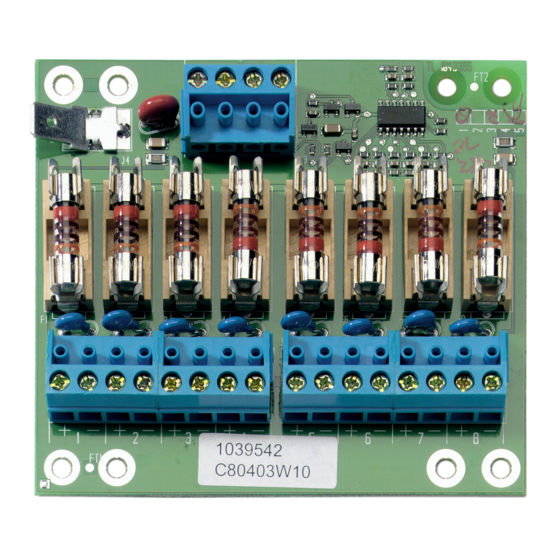
Description
ATS1840 is an 8-way fuse board to provide for separate fused
power supply outputs. Fuse fail is indicated by a dedicated
output that can be connected directly to any zone on the ATS
control panel (or ATS1201 DGP).
Figure
Item
Description
Function
(1)
Mains fail
Connected to zone input on control panel or
detection
DGP.
When no fuse fail present output equals
standard end-of-line resistor value (4.7 kΩ).
In case of fuse fail present output equals
double end-of-line resistor value (9.4 kΩ).
(2)
Power supply
Connected to (auxilliary) power output from
input
control panel or DGP.
(3)
Earth tab
Connected to system earth
(4)
Fuses
Fuses to provide for fused power supply
outputs
(5)
Power supply
8 power supply outputs, separately fused.
outputs
© 2021 Carrier
(2)
(4)
(5)
Mounting
The ATS1840 can be mounted into any ATS control panel or
ATS1201 DGP using the spacers provided.
To mount ATS1840 into the Advisor Master control panel
or ATS1201 DGP:
1.
Place the clips in the square holes (4) (use metal pillars
when available).
2.
Mount the ATS1840 using screws.
Connecting the ATS1840
1.
Connect (auxiliary) power supply from the control panel or
DGP to "+12 V" and "0 V" (J3).
2.
Connect "OUT" and "C" (J3) to a zone input on the control
panel/DGP. "C" needs to be connected to "C" of the zone
input.
3.
Connect required fused power supply to power supply
outputs 1 to 8 (J1/J2).
Specifications
Power supply
Supply power in (J3)
Supply power out (J1, J2)
Max. output current per output
ATS1840 current consumption
Environmental
Dimensions
Weight
Operating temperature
Humidity
Fuses
F1–F8
Fuse fail output
*
The sum of all output currents is restricted by the auxiliary fuse of
the control panel and the local requirements for the system load.
Regulatory information
Manufacturer
PLACED ON THE MARKET BY:
Carrier Fire & Security Americas Corporation Inc.
13995 Pasteur Blvd
Palm Beach Gardens, FL 33418, USA
AUTHORIZED EU REPRESENTATIVE:
Carrier Fire & Security B.V.
Kelvinstraat 7, 6003 DH Weert, Netherlands
1 / 4
Nominal 13.8 V
Nominal 13.8 V
315 mA*
3 mA
90 x 80 x 20 mm
125 g
−10 to +55°C
< 95% noncondensing
315 mA, fast 20x5
4.7 kΩ (no fuse fail)
9.4 kΩ (fuse fail)
P/N 466-5614 (ML) • REV A • ISS 17JUN21

Verwandte Anleitungen für Aritech ATS1840


Inhaltszusammenfassung für Aritech ATS1840
- Seite 1 ATS1840 Fuse Board Installation Sheet EN DE FR Mounting The ATS1840 can be mounted into any ATS control panel or ATS1201 DGP using the spacers provided. To mount ATS1840 into the Advisor Master control panel or ATS1201 DGP: Place the clips in the square holes (4) (use metal pillars when available).
- Seite 2 Montage www.aritech.com. REACH Product may contain substances that are also Die ATS1840 Platine kann mithilfe der mitgelieferten Candidate List substances in a concentration Abstandshalter in eine beliebige ATS-Einbruchmeldezentrale above 0.1% w/w, per the most recently published oder ATS1201/3/4 AME montiert werden.
- Seite 3 0,1 % w/w gemäß der zuletzt Montage veröffentlichten Kandidatenliste auf der ECHA- L’ATS1840 doit être placé dans le coffret de la centrale ATS ou Website aufgeführt sind. d’un ATS1201 DGP en utilisant les entretoises fournies à cet Informationen zur sicheren Verwendung finden effet.
- Seite 4 La somme de tous les courants sur les sorties est limitée par la protection située sur l’alimentation de la carte de la centrale ou du www.firesecurityproducts.com. DGP alimentant l’ATS1840, et dépend des spécifications nationales applicables. Information réglementaire MISE SUR LE MARCHÉ PAR : Fabriquant Carrier Fire &...