Heroal MT-4 Betriebsanleitung
Motorsteuerung
Vorschau ausblenden
Andere Handbücher für MT-4:
- Montageanleitung (32 Seiten) ,
- Betriebs- und montageanleitung (32 Seiten) ,
- Montage- und betriebsanleitung (24 Seiten)
Inhaltsverzeichnis
Fehlerbehebung

Verwandte Anleitungen für Heroal MT-4


Inhaltszusammenfassung für Heroal MT-4
- Seite 1 Motorsteuerung MT-4 heroal Motor Control System MT-4 Commande moteur heroal MT-4 heroal motorbesturing MT-4 Betriebsanleitung Operating manual Manuel d’utilisation Gebruiksaanwijzing...
- Seite 2 Internet: http://www.heroal.com Ce manuel d’utilisation est destiné à l’exploitant Deze gebruiksaanwijzing is bestemd voor de de la commande de portes roulantes MT-4 et à exploitant van de roldeurbesturing MT-4 en son personnel. Il contient des textes, images et zijn personeel. Ze bevat teksten, afbeeldingen schémas, pour lesquels l’accord explicite de Sté.
-
Seite 3: Inhaltsverzeichnis
Inhalt 1 Allgemeine Beschreibung 1.1 Hinweise zur Betriebsanleitung 1.2 Gestaltung der Betriebsanleitung 1.3 Nutzung der Betriebsanleitung 1.4 Verpflichtungen des Betreibers 1.5 Hinweis auf Schulungen 1.6 Anforderungen an das Personal 1.7 Gefahren im Umgang mit dem Gerät 1.8 Bestimmungsgemäße Verwendung 1.9 Vernünftigerweise vorhersehbare Fehlanwendungen 1.10 Mängelansprüche und Haftung 2 Allgemeine Sicherheitshinweise 2.1 Sicherheitssymbole in dieser Betriebsanleitung... - Seite 4 6.1.2 Grundfunktion 6.1.3 Reversier-Betrieb 6.1.4 Schaltfunktion Relais 4 (230 V) 6.1.5 Schaltfunktion Relais 5 (potentialfrei) 6.1.6 Zusatzfunktionen 6.2 Leiterplatte MT-4 6.3 Anschlussplan für 230 V Motor 6.4 Anschlussplan für die Eingänge 6.5 Anschlussplan für Lichtschranke HC in der Tordurchfahrt 7 Betrieb 7.1 Sicherheitshinweise...
- Seite 5 Inhalt 8 Wartung und Pflege 8.1 Sicherheitshinweise 8.2 Wartungstabelle 9 Störungsbehebung 9.1 Sicherheitshinweise 9.2 Störungen im Arbeitsablauf 9.3 Instandsetzung 9.4 LED Zustands- und Störungstabelle 10 Entsorgung 11 Konformitätserklärung Allgemeine Geschäftsbedingungen Original - Betriebsanleitung 02.2022 | 05...
-
Seite 6: Allgemeine Beschreibung
In diesem Kapitel finden Sie Hinweise zu dieser Betriebsanleitung, sowie allgemeine Sicherheitshinweise im Umgang mit der Rolltorsteuerung MT-4. Im weiteren Verlauf wird die Rolltorsteuerung MT-4 auch als Gerät bezeichnet. 1.1 Hinweise zur Betriebsanleitung Diese Betriebsanleitung ist zentraler Bestandteil der Benutzerdokumentation des Gerätes. -
Seite 7: Nutzung Der Betriebsanleitung
Motorsteuerung MT-4 1 Allgemeine Beschreibung 1.3 Nutzung der Betriebsanleitung Diese Betriebsanleitung dient dazu, das Gerät kennen zu lernen und deren bestimmungsgemäße Einsatzmöglichkeiten zu nutzen. Die Betriebsanleitung ist aufgrund bestehender nationaler Vorschriften zur Unfallverhütung und zum Umweltschutz um Anweisungen zu ergänzen. -
Seite 8: Hinweis Auf Schulungen
1.5 Hinweis auf Schulungen Um eine ausreichende Vertrautheit mit dem Gerät zu ermöglichen, wird das Be- dienpersonal durch Mitarbeiter der Firma heroal - Johann Henkenjohann GmbH & Co. KG eingewiesen. Die Teilnehmer werden angewiesen, das übrige Personal anzulernen. -
Seite 9: Gefahren Im Umgang Mit Dem Gerät
Motorsteuerung MT-4 1 Allgemeine Beschreibung So dürfen zum Beispiel Arbeiten an der elektrischen Ausrüstung des Gerätes nur von einer speziell dafür ausgebildeten Fachkraft oder von unterwiesenen Personen unter Leitung und Aufsicht einer solchen Fachkraft gemäß den dafür geltenden technischen Regeln vorgenommen werden. -
Seite 10: Bestimmungsgemäße Verwendung
Relaisausgänge sind mit einem Maximalstrom von 4 A belastbar. Zur Funkfernsteuerung der MT-4 stehen verschiedene Handsender zur Verfügung. Der MT-4 Empfänger kann mit 1 bis 4-Kanal Sendern kombiniert werden. Für die Funkübertragung wird das ISM-Band mit 433,92 MHz benutzt. Dieser Bereich ist für diese Art von Anwendung durch die Bundesnetzagentur freigegeben. -
Seite 11: Vernünftigerweise Vorhersehbare Fehlanwendungen
Motorsteuerung MT-4 1 Allgemeine Beschreibung 1.9 Vernünftigerweise vorhersehbare Fehlanwendungen Als Fehlanwendung gilt insbesondere: » das Verwenden und Anschließen/Einbauen von nicht zugelassenen Bauteilen. » das Betreiben des Gerätes mit einer anderen Netzspannung als auf dem Gerät angegeben. » die Fernsteuerung von Rolltoren und Rollgittern mit erhöhtem Unfallrisiko. -
Seite 12: Allgemeine Sicherheitshinweise
Motorsteuerung MT-4 2 Allgemeine Sicherheitshinweise 2.1 Sicherheitssymbole in dieser Betriebsanleitung GEFAHR „GEFAHR“ kennzeichnet eine unmittelbare drohende Gefahr, die zu schweren Körperverletzungen oder zum Tod führt. WARNUNG „WARNUNG“ kennzeichnet eine möglicherweise gefährliche Situation, die zu schweren Körperverletzungen oder zum Tod führen könnte. -
Seite 13: Allgemeine Sicherheitshinweise
Motorsteuerung MT-4 2 Allgemeine Sicherheitshinweise 2.2 Allgemeine Sicherheitshinweise GEFAHR Gefährdung von Personen an dem Gerät! » Die Betriebsanleitung ständig am Einsatzort griffbereit aufbewahren. » Der Bediener des Gerätes muss die Betriebsanleitung gelesen und verstanden haben. » Arbeitsanweisungen beachten. » Das Anschließen von selbstgebauten Produkten an die Motorsteuerung ist untersagt. -
Seite 14: Sicherheitshinweise Zum Betrieb
Motorsteuerung MT-4 2 Allgemeine Sicherheitshinweise WARNUNG Gefährdung durch das Gerät! » Gerät bestimmungsgemäß verwenden. » Gerät in technisch einwandfreiem, betriebsbereitem und funktionssicherem Zustand benutzen. » Erst Schäden an dem Gerät fachgerecht durch den Her- steller, dessen Kundendienst oder eine qualifizierte Person reparieren lassen, dann Gerät in Betrieb nehmen. - Seite 15 Motorsteuerung MT-4 2 Allgemeine Sicherheitshinweise GEFAHR Verletzungsgefahr von Personen durch das Gerät und das Tor! » Das Gerät kann von Kindern ab 8 Jahren und darüber sowie von Personen mit verringerten physischen, sensorischen und mentalen Fähigkeiten oder Mangel an Erfahrung und Wissen benutzt werden, wenn sie beaufsichtigt oder bezüglich des...
-
Seite 16: Sicherheitshinweise Zu Einrichtarbeiten, Wartung, Instandhaltung
Motorsteuerung MT-4 2 Allgemeine Sicherheitshinweise 2.4 Sicherheitshinweise zu Einrichtarbeiten, Wartung, Instandhaltung, Störungsbehebung GEFAHR Gefährdung von Personen durch Stromschlag! » Alle elektronischen Komponenten, Antrieb und Regel- und/ oder Steuereinrichtungen, müssen während der Reinigung, der Instandhaltung und beim Austausch von Teilen von seiner Stromversorgung getrennt sein. - Seite 17 Motorsteuerung MT-4 2 Allgemeine Sicherheitshinweise GEFAHR Verletzungsgefahr durch unerwartetes Wiedereinschalten! » Montage, Wartung und Einstellungen dürfen nur von Fach- personal erfolgen. » Arbeiten an dem Gerät sind nur bei abgeschalteter Netz- spannung zulässig. » Gerät vor Einricht- und Wartungsarbeiten, bei Instandhal- tung und Störungsbehebung vom Stromnetz trennen und...
-
Seite 18: Technische Daten
Motorsteuerung MT-4 3 Technische Daten 3.1 Gesamtes Gerät Gerätebezeichnung: Rolltorsteuerung MT-4 Abmaße (L x B x H): ca. 180 x 130 x 62 mm Gewicht: 0,7 kg Schutzart: IP 65 Betriebstemperatur: -10 °C - +55 °C Lagertemperatur: -20 °C - +70 °C Kabelöffnungen:... -
Seite 19: Aufbau Und Funktion
Motorsteuerung MT-4 4 Aufbau und Funktion 4.1 Gesamtes Gerät Das Gerät dient dem automatischen Betrieb von Rolltoren und Rollgittern. Der Mikroprozessor im Inneren des Gerätes bietet viele Bedien- und Anschlussmöglichkeiten und steuert sämtliche Abläufe. Zur Versorgung von Lichtschranken und Befehlsgebern ist ein 24 V DC Netzteil integriert. -
Seite 20: Installation Und Einsatzbereiche Des Gerätes
5.3 Einsatzbereiche Bei der neuen Motorsteuerung MT-4 handelt es sich um eine moderne Torsteuerung, die den Anforderungen der Torindustrie entspricht. Alle geltenden und bis dato geplanten europäischen Normen und Richtlinien sind in vollem Umfang integriert (Parametrierung erfolgt über DIL-Schalter). -
Seite 21: Meldelinien
Motorsteuerung MT-4 5 Installation und Einsatzbereiche des Gerätes 5.4.3 Meldelinien Die Meldelinien (Relais mit Schließerkontakt) sind abhängig von den Programm- einstellungen der DIL-Schalter (siehe Kapitel 6.1 „Programmeinstellung DIL-Schalter 10-polig“). Meldung Tor offen Kl. 8+9 (6+7, 230 V) Meldung Tor geschlossen Kl. -
Seite 22: Zusatzfunktionen
Motorsteuerung MT-4 5 Installation und Einsatzbereiche des Gerätes 5.4.6 Zusatzfunktionen Automatisch schließen (einstellbar über Drehschalter auf Grundplatine) Stellung 0 Automatisch Schließen aus Stellung 1 Offenzeit 10 sec. Stellung 2 Offenzeit 20 sec. Stellung 3 Offenzeit 30 sec. Stellung 4 Offenzeit 30 sec. mit Verkürzung auf 4 sec. -
Seite 23: Notbedienung
Motorsteuerung MT-4 5 Installation und Einsatzbereiche des Gerätes 5.5.2 Notbedienung Die Motorsteuerung MT-4 beinhaltet eine automatische Abschaltung der Abwärtsbewegung des Tores im Fehlerfall. Ist z.B. die Lichtschranke oder die Sicherheitsschaltleiste defekt, können die Rolltore und Rollgitter nur noch bei betätigter Taste geöffnet werden. Eine Umschaltung in den Totmann-Betrieb für die Abwärtsbedienung wird nicht unterstützt. - Seite 24 Motorsteuerung MT-4 5 Installation und Einsatzbereiche des Gerätes Rollgitter offene Montage: Absicherung des Einlaufbereichs mit zwei Lichtschranken. Zusätzliche Lichtschranke unter der Decke nur erforderlich, wenn A < 2500 mm und gleichzeitig B < 80 mm (bei aufgerolltem Tor). Rollgitter mit Kasten: Absicherung des Einlaufbereichs mit zwei Lichtschranken.
-
Seite 25: Inbetriebnahme
Motorsteuerung MT-4 6 Inbetriebnahme Voraussetzungen: » Das Gerät ist mit dem Stromnetz verbunden, der Netzstecker ist eingesteckt. » Motorleitung ist angeschlossen. Arbeitsschritte: HINWEIS » Vor der Kontrolle und Einstellung der Drehrichtung des Motors und der Endlagenschalter muss der DIL-Schalter 1 in Stellung „OFF“... -
Seite 26: Programmeinstellung Dil-Schalter 10-Polig
Motorsteuerung MT-4 6 Inbetriebnahme 6.1 Programmeinstellung DIL-Schalter 10-polig Mit den DIL-Schaltern 1 bis 10 werden die Betriebs- und Programm-Funktionen der MT-4 eingestellt. 6.1.1 Auslieferungszustand Auslieferungszustand 6.1.2 Grundfunktion Grundfunktion Auslieferungszustand Automatik-Betrieb Befehl „Tor-Ab“ wegen Testung leicht verzögert. Einstell-Betrieb 26 | 02.2022... -
Seite 27: Reversier-Betrieb
Motorsteuerung MT-4 6 Inbetriebnahme 6.1.3 Reversier-Betrieb Reversier-Betrieb Auslieferungszustand Tor bleibt in STOPP Position Auf-Befehl für 0,5 Sekunden Auf-Befehl bis zur Endlage Tor bleibt in STOPP Position, Zusätzlich TEST der Leiste Original - Betriebsanleitung 02.2022 | 27... -
Seite 28: Schaltfunktion Relais 4 (230 V)
Motorsteuerung MT-4 6 Inbetriebnahme 6.1.4 Schaltfunktion Relais 4 (230 V) Schaltfunktion Relais 4 (230 V) Auslieferungszustand Dauer-Signal 2 Minuten nach jedem AUF-Befehl Impuls 2 Sekunden nach einem AUF-Befehl Blink-Takt solange das Tor läuft Dauer-Signal solange das Tor offen ist 28 | 02.2022... -
Seite 29: Schaltfunktion Relais 5 (Potentialfrei)
Motorsteuerung MT-4 6 Inbetriebnahme 6.1.5 Schaltfunktion Relais 5 (potentialfrei) Schaltfunktion Relais 5 (potentialfrei) Auslieferungszustand Schaltsignal Tor STÖRUNG ROT-Ampel Betrieb mit Vorwarnung bei automatischer Schließung Schaltsignal Tor OFFEN 6.1.6 Zusatzfunktionen Zusatzfunktionen Lichtansteuerung sofort nach Öffnungsimpuls verzögert öffnen (Einstellung für Frankreich) Ohne Verzögerung öffnen (voreingestellt) Wartungszähler aktiv... -
Seite 30: Leiterplatte Mt
Motorsteuerung MT-4 6 Inbetriebnahme 6.2 Leiterplatte MT-4 1 2 3 30 | 02.2022 Original - Betriebsanleitung... -
Seite 31: Anschlussplan Für 230 V Motor
Motorsteuerung MT-4 6 Inbetriebnahme Pos. Bezeichnung Farbe Funktion PWR/GN grün POWER/Betriebsspannung in Ordnung anzeigen. SKS/RT LEISTE/Schaltleiste betätigt oder defekt anzeigen. Funk/GE gelb FUNK/Kontrolle für den Funkempfang und Lernen/ Löschen der Handsender anzeigen. 6.3 Anschlussplan für 230 V Motor Netz 230 V, 50 Hz Bei Verwendung Brücke entfernen... -
Seite 32: Anschlussplan Für Die Eingänge
Motorsteuerung MT-4 6 Inbetriebnahme 6.4 Anschlussplan für die Eingänge Abrollsicherung Not Bei Verwendung Stopp Brücke entfernen Bei Verwendung Stopp Brücke entfernen Folge Taste Bei Verwendung Lichtschranke 1 Brücke entfernen Tordurchfahrt in 0,5 m Höhe Lichtschranke 2 Bei Verwendung Tordurchfahrt in 1,0 m Höhe Brücke entfernen... -
Seite 33: Anschlussplan Für Lichtschranke Hc In Der Tordurchfahrt
Motorsteuerung MT-4 6 Inbetriebnahme 6.5 Anschlussplan für Lichtschranke HC in der Tordurchfahrt 10 11 12 13 14 15 16 17 18 19 20 21 22 23 24 25 26 SKS OSE LS 1 LS 2 Lichtschranke 1 Klemmbezeichnung Lichtschranke 2... -
Seite 34: Bedien- Und Kontrollelemente
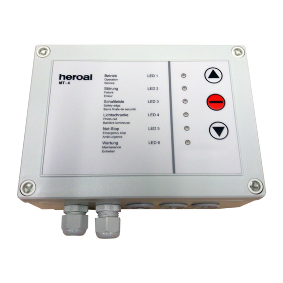
Motorsteuerung MT-4 7 Betrieb 7.2 Bedien- und Kontrollelemente Pos. Bezeichnung Farbe Funktion LED 1 - Betrieb grün Betrieb anzeigen. LED 2 - Störung Störung anzeigen. LED 3 - Schaltleiste gelb Auslöser Schaltleiste anzeigen. LED 4 - Lichtschranke Auslöser Lichtschranke anzeigen. -
Seite 35: Handsender Einlernen / Löschen
Motorsteuerung MT-4 7 Betrieb Voraussetzungen: » Optische Kontrolle des Gerätes ist erfolgt, Gerät ist in Ordnung. » Das Gerät ist mit dem Stromnetz verbunden. Arbeitsschritte: 1. Das Tor in die gewünschte Position mit den Tastern „rauf“ oder „runter“ bewegen und mit dem Taster „Stopp“ stoppen. -
Seite 36: Wartung Und Pflege
Motorsteuerung MT-4 8 Wartung und Pflege Um die reibungslose, bestimmungsgemäße Verwendung des Gerätes zu erhalten, sind die in diesem Kapitel behandelten Pflege- und Wartungsarbeiten erforderlich. Regelmäßige Pflege und Wartung verlängern die Lebensdauer und erhöhen den Nutzungsgrad. Für den sicheren Betrieb des Gerätes sind die Wartungsarbeiten regelmäßig auszuführen und die Intervalle einzuhalten. -
Seite 37: Störungsbehebung
Motorsteuerung MT-4 9 Störungsbehebung 9.1 Sicherheitshinweise GEFAHR Sicherheitshinweise beachten! » Die Sicherheitshinweise in Kapitel 2.2 „Allgemeine Sicher- heitshinweise“, insbesondere im Kapitel 2.4 „Sicherheitshin- weise zu Einrichtarbeiten, Wartung, Instandhaltung, Stö- rungsbehebung“ beachten. 9.2 Störungen im Arbeitsablauf Bei Störungen im Arbeitsablauf des Gerätes das Fachpersonal informieren. -
Seite 38: Led Zustands- Und Störungstabelle
Motorsteuerung MT-4 9 Störungsbehebung 9.4 LED Zustands- und Störungstabelle LED 1 grün LED 2 rot LED 3 gelb Zustand/Störung Abhilfe/Lösung blinkt Das Tor läuft. Alles in Ordnung. gleichmäßig blinkt lange Die Offenzeit läuft ab. Warnung. - AN, Das Tor läuft gleich an. -
Seite 39: Entsorgung
Motorsteuerung MT-4 10 Entsorgung Zur Entsorgung ist das Gerät fachgerecht zu zerlegen und in Einzelteilen einer sachgerechten Verwertung zuzuführen. HINWEIS Umweltverschmutzung! » Austauschteile sicher und umweltschonend entsorgen. Folgende Punkte sind bei der Entsorgung zu beachten: » Vor Beginn der Arbeiten das Gerät vom Stromnetz trennen. -
Seite 40: Konformitätserklärung
Motorsteuerung MT-4 11 Konformitätserklärung EG-Konformitätserklärung im Sinne der EG-Richtlinie Maschinen 2006/42/EG Hiermit erklären wir, die Firma heroal Johann Henkenjohann GmbH & Co. KG Österwieher Str. 80 33415 Verl (Germany) Fon +49 5246 507-0 Fax +49 5246 507-222 dass die Vorrichtung... -
Seite 41: Allgemeine Geschäftsbedingungen
Allgemeine Geschäftsbedingungen heroal - Johann Henkenjohann GmbH & Co. KG, Österwieher Str. 80, 33415 Verl § 1 Geltung der Bedingungen 1. Unsere Lieferungen, Leistungen und Angebote erfolgen ausschließlich aufgrund dieser Geschäftsbedingungen. Diese gelten somit auch für alle künftigen Geschäftsbeziehungen, auch wenn sie nicht nochmals ausdrücklich vereinbart werden. - Seite 42 Allgemeine Geschäftsbedingungen heroal - Johann Henkenjohann GmbH & Co. KG, Österwieher Str. 80, 33415 Verl sen haben. Unsere gesetzlichen Rücktritts- und Kündigungsrechte sowie die gesetzlichen Vorschriften über die Abführung des Vertrages bei einem Ausschluss der Leistungspflicht (z. B. Unmöglichkeit oder Unzumutbarkeit der Leistung und/oder Nacherfüllung) bleiben unberührt.
- Seite 43 Allgemeine Geschäftsbedingungen heroal - Johann Henkenjohann GmbH & Co. KG, Österwieher Str. 80, 33415 Verl § 6 Gewährleistung 1. Der Kunde ist verpflichtet, die gelieferte Ware sofort nach Erhalt auszupacken und zu prüfen (§ 377 HGB). Be- anstandungen jeder Art sind innerhalb von 8 Tagen nach Lieferung schriftlich anzuzeigen. Versteckte Mängel sind sofort nach ihrer Feststellung, spätestens jedoch 10 Tage nach Feststellung uns anzuzeigen.
- Seite 44 Notizen 44 | 08.2020 Original - Betriebsanleitung...
- Seite 45 Notizen Original - Betriebsanleitung 08.2020 | 45...
- Seite 46 Notizen 46 | 08.2020 Original - Betriebsanleitung...
- Seite 47 Contents 1 General description 1.1 Information on the operating instructions 1.2 Design of the operating instructions 1.3 Using the operating instructions 1.4 Obligations of the operator 1.5 Training information 1.6 Personnel requirements 1.7 Dangers when using the device 1.8 Proper use 1.9 Reasonably foreseeable misuse 1.10 Claims for defects and liability 2 General safety information...
- Seite 48 6.1.4 Switching function relay 4 (230 V) 6.1.5 Switching function relay 5 (potential-free) 6.1.6 Auxiliary functions 6.2 MT-4 circuit board 6.3 Wiring diagram for 230 V motor 6.4 Wiring diagram for inputs 6.5 Wiring diagram for light barrier HC in the door opening 7 Operation 7.1 Safety information...
- Seite 49 Contents 8 Maintenance and servicing 8.1 Safety information 8.2 Maintenance table 9 Troubleshooting 9.1 Safety information 9.2 Faults during the work process 9.3 Repairs 9.4 LED status and fault table 10 Disposal 11 Declaration of conformity General terms and conditions Original operating instructions 02.2022 | 05...
-
Seite 50: General Description
This chapter includes information on these operating instructions, as well as general safety information for handling the Roller door controller MT-4. The roller door controller MT-4 will also be referred to as the device in the remainder of this document. -
Seite 51: Using The Operating Instructions
Motor Control System MT-4 1 General description 1.3 Using the operating instructions These operating instructions are designed to help the operator understand the device and use it in accordance with its proper use. These operating instructions must be supplemented with applicable national accident prevention regulations and environmental protection guidelines. -
Seite 52: Training Information
1.5 Training information In order to ensure they are sufficiently familiar with the device, operating personnel will be trained by employees of the company heroal - Johann Henkenjohann GmbH & Co. KG. Participants will be instructed to train other personnel. -
Seite 53: Dangers When Using The Device
Motor Control System MT-4 1 General description For example, work on the electrical equipment of the device may only be carried out by specially trained technicians or trained personnel, under the guidance and supervision of such technicians, and in accordance with applicable technical infor- mation. -
Seite 54: Proper Use
4 A. There are different handheld transmitters available for remote control of the MT-4. The MT-4 receiver can be combined with 1 to 4-channel transmitters. The 433.92 MHz ISM band is used for radio transmission. This range is approved for this type of use by the Federal Network Agency. -
Seite 55: Reasonably Foreseeable Misuse
Motor Control System MT-4 1 General description 1.9 Reasonably foreseeable misuse Misuse includes, in particular: » using and connecting/installing prohibited components. » operating the device with a mains voltage different than that indicated on the device. » remote controlling roller doors and roller grilles with an increased risk of ac- cidents. -
Seite 56: General Safety Information
Motor Control System MT-4 2 General safety information 2.1 Safety symbols used in these operating instructions DANGER “DANGER” indicates a direct, imminent danger that will result in serious physical injuries or death. WARNING “WARNING” indicates a possibly dangerous situation that could result in serious physical injuries or death. -
Seite 57: General Safety Information
Motor Control System MT-4 2 General safety information 2.2 General safety information DANGER Danger to personnel on the device! » Always keep these operating instructions available at the work site. » The device operator must have read and understood the operating instructions. -
Seite 58: Safety Information For Operation
Motor Control System MT-4 2 General safety information WARNING Danger posed by the device! » Use the device as intended. » Only use the device if it is in proper technical, functional and ready to operate condition. » Have damages to the device professionally repaired by the manufacturer, its customer service or a qualified individual before beginning operation. - Seite 59 Motor Control System MT-4 2 General safety information DANGER Risk of injury to personnel from the device and the door! » The device may be used by children 8 years of age and older, as well as by persons with reduced physical, sensory and...
-
Seite 60: Safety Information On Set-Up Work, Maintenance, Repairs And Troubleshooting
Motor Control System MT-4 2 General safety information 2.4 Safety information on set-up work, maintenance, repairs and troubleshooting DANGER Danger to personnel from electric shock! » All electronic components, drives and regulation and/or control devices must be disconnected from the power supply during cleaning, maintenance and when exchanging parts. - Seite 61 Motor Control System MT-4 2 General safety information DANGER Risk of injury due to unexpected restart! » Assembly, maintenance and setting work may only be carried out by professional technicians. » Work on the device may only be carried out with the mains voltage turned off.
-
Seite 62: Technical Data
Motor Control System MT-4 3 Technical data 3.1 Overall device Device designation: Roller Door Control System MT-4 Dimensions (L x W x H): approx. 180 x 130 x 62 mm Weight: 0.7 kg Degree of protection: IP 65 Operating temperature: -10 °C - +55 °C... -
Seite 63: Structure And Function
Motor Control System MT-4 4 Structure and function 4.1 Overall device The device is used for automatic operation of roller doors and roller grilles. The microprocessor inside the device offers a variety of operating and connection options, and controls all processes. -
Seite 64: Installation And Range Of Application Of The Device
5.2 Installation The Motor control system MT-4 is delivered with a mains cable and front keyboard as standard features. After the motor line is connected, the device is immediately ready to commission. Please observe the relevant wiring diagrams. The mains plug replaces the main power switch of the device, and therefore must be easily accessible and may not be removed. -
Seite 65: Detection Lines
Motor Control System MT-4 5 Installation and range of application of the device 5.4.3 Detection lines The detection lines (relay with make contact) are dependent on the program set- tings of the DIL switch (see section 6.1 “DIL switch program settings 10 pole”). -
Seite 66: Auxiliary Functions
Motor Control System MT-4 5 Installation and range of application of the device 5.4.6 Auxiliary functions Automatic closure (adjustable using rotary switch on motherboard) Position 0 Automatic closure off Position 1 Max. opening time 10 sec. Position 2 Max. opening time 20 sec. -
Seite 67: Emergency Operation
5 Installation and range of application of the device 5.5.2 Emergency operation The motor control system MT-4 includes a function to automatically switch off downward motion of the door in case of a fault. For instance, if the light barrier or a safety end slat is defective, roller doors and roller grilles can only be opened... - Seite 68 Motor Control System MT-4 5 Installation and range of application of the device Roller grille open installation: Securing the intake area with two light barriers. Additional light barrier under the ceiling is only required if A < 2500 mm and at the same time B < 80 mm (with the door rolled up).
-
Seite 69: Commissioning
Motor Control System MT-4 6 Commissioning Requirements: » The device is connected to the power grid and the plug is plugged in. » Motor line is connected. Work steps: NOTE » DIL switch 1 must be in the “OFF” position (setting mode) before checking and setting the direction of rotation of the motor and end limit switch. -
Seite 70: Program Setting Dil Switch 10 Pole
Motor Control System MT-4 6 Commissioning 6.1 Program setting DIL switch 10 pole DIL switches 1 to 10 are used to set the operating and program functions of the MT-4. 6.1.1 Defaults Default 6.1.2 Basic function Basic function Default Automatic mode “Door down”... -
Seite 71: Reverse Operation
Motor Control System MT-4 6 Commissioning 6.1.3 Reverse operation Reverse operation Default Door remains in STOP position Up command for 0.5 seconds Up command to the end position Door remains in STOP position, additional TEST of the slat Original operating instructions... -
Seite 72: Switching Function Relay 4 (230 V)
Motor Control System MT-4 6 Commissioning 6.1.4 Switching function relay 4 (230 V) Switching function relay 4 (230 V) Default Continuous signal 2 minutes after every UP command Pulse 2 seconds after an UP command Flashing cycle as long as the door is... -
Seite 73: Switching Function Relay 5 (Potential-Free)
Motor Control System MT-4 6 Commissioning 6.1.5 Switching function relay 5 (potential-free) Switching function relay 5 (potential-free) Default Switching signal door FAULT RED light operation with pre-warning during automatic closing Switching signal door OPEN 6.1.6 Auxiliary functions Auxiliary functions Delayed opening of light activa-... -
Seite 74: Mt-4 Circuit Board
Motor Control System MT-4 6 Commissioning 6.2 MT-4 circuit board 1 2 3 30 | 02.2022 Original operating instructions... -
Seite 75: Wiring Diagram For 230 V Motor
Motor Control System MT-4 6 Commissioning Pos. Description Colour Function PWR/GN green POWER/Display operating voltage OK. SKS/RT SLAT/Display safety edge activated or defective. Radio/GE yellow RADIO/Display control for radio receipt and teaching/ deleting the handheld transmitters. 6.3 Wiring diagram for 230 V motor... -
Seite 76: Wiring Diagram For Inputs
Motor Control System MT-4 6 Commissioning 6.4 Wiring diagram for inputs Anti-fall device emer- Remove bridge gency stop during use Remove bridge Stop during use Open Closed Button sequence Remove bridge Light barrier 1 during use Door passage at 0.5 m height... -
Seite 77: Wiring Diagram For Light Barrier Hc In The Door Opening
Motor Control System MT-4 6 Commissioning 6.5 Wiring diagram for light barrier HC in the door opening 10 11 12 13 14 15 16 17 18 19 20 21 22 23 24 25 26 SKS OSE LS 1 LS 2... -
Seite 78: Operating And Control Elements
Motor Control System MT-4 7 Operation 7.2 Operating and control elements Pos. Description Colour Function LED 1 - Operation green Indicates operation. LED 2 - Fault Indicates a fault. LED 3 - Safety edge yellow Indicates a safety edge triggered. -
Seite 79: Teach In / Delete Handheld Transmitter
Motor Control System MT-4 7 Operation Requirements: » Visual inspection of the device is completed and the device is in proper condition. » The device is connected to the power network. Work steps: 1. Move the door to the desired position using the “up” and “down” buttons and stop it using the “stop”... -
Seite 80: Maintenance And Servicing
Motor Control System MT-4 8 Maintenance and servicing To maintain smooth and proper use of the device, the servicing and maintenance work described in this section must be performed. Regular maintenance and servicing will extend the service life and improve the usability of the device. -
Seite 81: Troubleshooting
Motor Control System MT-4 9 Troubleshooting 9.1 Safety information DANGER Observe the safety information! » Observe the safety information in section 2.2 “General safety information”, and in particular in section 2.4 “Safety information for set-up work, maintenance, repair and troubleshooting”. -
Seite 82: Led Status And Fault Table
Motor Control System MT-4 9 Troubleshooting 9.4 LED status and fault table LED 1 green LED 2 red LED 3 yellow Status/fault Correction/solution flashes The door is running. Everything is OK. regularly long flash The max. opening time is Warning. -
Seite 83: Disposal
Motor Control System MT-4 10 Disposal The device must be professionally disassembled and the individual parts must be disposed of properly. NOTE Environmental contamination! » Dispose of exchanged parts in a safe and environmental- ly-friendly manner. The following must be observed during disposal: »... -
Seite 84: Declaration Of Conformity
11 Declaration of conformity EC Declaration of Conformity in accordance with the EC Machinery Directive 2006/42/EC We, the company heroal Johann Henkenjohann GmbH & Co. KG Österwieher Str. 80 33415 Verl (Germany) Phone +49 5246 507-0 Fax +49 5246 507-222... -
Seite 85: General Terms And Conditions
General terms and conditions heroal - Johann Henkenjohann GmbH & Co. KG, Österwieher Str. 80, 33415 Verl § 1 Scope of the conditions 1. Our deliveries, services and offers are all provided on the basis of these General terms and conditions. Therefore, these conditions apply to all future business relationships, even if they are not expressly agreed to again in the future. - Seite 86 General terms and conditions heroal - Johann Henkenjohann GmbH & Co. KG, Österwieher Str. 80, 33415 Verl 3. The customer is entitled to default claims if we are responsible for the delay. In any case, however, the customer must provide a warning. If we or our agents are guilty of only slight negligence in a breach of duty, then our liability shall be limited to the foreseeable damages typical for the type of contract involved.
- Seite 87 General terms and conditions heroal - Johann Henkenjohann GmbH & Co. KG, Österwieher Str. 80, 33415 Verl § 6 Warranty 1. The customer is obligated to remove goods from packaging and inspect them immediately upon receipt (§ 377 HGB). Written notification must be sent within 8 days of the delivery if there is any kind of complaint. We must be notified of hidden defects immediately upon discovery, and at the latest 10 days after they are discovered.
- Seite 88 Notes 44 | 02.2022 Original operating instructions...
- Seite 89 Notes Original operating instructions 02.2022 | 45...
- Seite 90 Notes 46 | 02.2022 Original operating instructions...
- Seite 91 Sommaire 1 Description générale 1.1 Informations sur le mode d’emploi 1.2 Structure du mode d’emploi 1.3 Utilisation du mode d'emploi 1.4 Obligations de l’exploitant 1.5 Informations sur les formations 1.6 Exigences relatives au personnel 1.7 Risques liés à la manipulation de l’appareil 1.8 Utilisation conforme 1.9 Usages inadéquats raisonnablement prévisibles 1.10 Réclamations en cas de défaut et responsabilité...
- Seite 92 6.1.4 Fonction de commutation Relais 4 (230 V) 6.1.5 Fonction de commutation Relais 5 (sans potentiel) 6.1.6 Fonctions supplémentaires 6.2 Circuit imprimé MT-4 6.3 Plan de raccordement du moteur 230 V 6.4 Plan de raccordement pour les entrées 6.5 Plan de raccordement pour barrière lumineuse HC dans...
- Seite 93 Sommaire 7.4 Programmer / supprimer un émetteur manuel 7.5 Éteindre l’appareil 8 Maintenance et entretien 8.1 Consignes de sécurité 8.2 Tableau de maintenance 9 Dépannage 9.1 Consignes de sécurité 9.2 Défauts pendant le fonctionnement 9.3 Réparation 9.4 Tableau d'état et de défaut LED 10 Mise au rebut 11 Déclaration de conformité...
-
Seite 94: Description Générale
Dans ce chapitre, vous trouverez des informations sur ce mode d’emploi ainsi que des consignes de sécurité générales relatives à la manipulation de la commande pour portes roulantes MT-4. Par la suite, la commande pour portes roulantes MT-4 est également désignée comme un appareil. 1.1 Informations sur le mode d’emploi Ce mode d’emploi est un élément central de la documentation utilisateur de... -
Seite 95: Utilisation Du Mode D'emploi
Commande moteur MT-4 1 Description générale 1.3 Utilisation du mode d'emploi Ce mode d'emploi sert à se familiariser avec l'appareil et à utiliser ses fonctions de façon conforme. Le mode d'emploi doit être complété avec des instructions en fonction des dispositions nationales applicables relatives à... -
Seite 96: Informations Sur Les Formations
1.5 Informations sur les formations Afin de permettre une maîtrise suffisante de l'appareil, le personnel d’exploitation sera formé par les employés de l’entreprise heroal - Johann Henkenjohann GmbH & Co. KG. Les participants seront invités à former le reste du personnel. -
Seite 97: Risques Liés À La Manipulation De L'appareil
Commande moteur MT-4 1 Description générale Ainsi, les travaux sur l'équipement électrique de l’appareil doivent uniquement être réalisés par du personnel spécialement qualifié ou formé sous la direction et la surveillance de ce type de personnel conformément aux règles techniques applica- bles. -
Seite 98: Utilisation Conforme
éléments de commande. Les sorties relais peuvent supporter un courant maximum de 4 A. Différents émetteurs manuels sont disponibles pour la commande radio du MT-4. Le récepteur MT-4 peut être combiné avec des émetteurs comportant de 1 à 4 canaux. -
Seite 99: Usages Inadéquats Raisonnablement Prévisibles
Commande moteur MT-4 1 Description générale 1.9 Usages inadéquats raisonnablement prévisibles Les utilisations inappropriées incluent notamment : » L’utilisation et le raccordement/montage d'éléments non autorisés. » L’utilisation de l’appareil avec une autre tension secteur que celle spécifiée sur l’appareil. » La commande à distance de portes roulantes et de grilles à enroulement avec un risque d'accident renforcé. -
Seite 100: Consignes Générales De Sécurité
Commande moteur MT-4 2 Consignes générales de sécurité 2.1 Symboles de sécurité dans ce mode d’emploi DANGER « DANGER » désigne un danger immédiat provoquant des blessures physiques graves ou un décès. AVERTISSEMENT « AVERTISSEMENT » désigne une situation potentiellement dangereuse susceptible de provoquer des blessures physiques graves ou un décès. -
Seite 101: Consignes Générales De Sécurité
Commande moteur MT-4 2 Consignes générales de sécurité 2.2 Consignes générales de sécurité DANGER Mise en danger des personnes par l’appareil ! » Conserver constamment le mode d’emploi à portée de main sur le lieu d’exploitation. » L'opérateur de l’appareil doit avoir lu et compris le mode d’emploi. -
Seite 102: Remarques De Sécurité Pour L'exploitation
Commande moteur MT-4 2 Consignes générales de sécurité AVERTISSEMENT Mise en danger par l’appareil ! » Utiliser l’appareil de façon conforme. » Utiliser l’appareil dans un bon état de fonctionnement tech- nique sécurisé. » Faire d'abord réparer les dommages sur l’appareil de façon conforme par le fabricant, son service-client ou une person- ne qualifiée, puis mettre l’appareil en service. - Seite 103 Commande moteur MT-4 2 Consignes générales de sécurité DANGER Risque de blessure des personnes par l’appareil et la porte ! » L’appareil peut être utilisé par des enfants à partir de 8 ans ainsi que par des personnes aux capacités physiques, senso- rielles et mentales réduites ou ayant un manque d’expérien-...
-
Seite 104: Consignes De Sécurité Pour Les Opérations De Réglage, La Maintenance, L'entretien, Le Dépannage
Commande moteur MT-4 2 Consignes générales de sécurité 2.4 Consignes de sécurité pour les opérations de réglage, la maintenance, l’entretien, le dépannage DANGER Mise en danger des personnes liée à un choc électrique ! » Tous les composants électroniques, les entraînements et les équipements de réglage et/ou de commande doivent être... - Seite 105 Commande moteur MT-4 2 Consignes générales de sécurité DANGER Risque de blessure en cas de remise en marche imprévue ! » Seul du personnel spécialisé doit réaliser le montage, la maintenance et les réglages. » Les travaux sur l’appareil sont uniquement autorisés si la tension secteur est coupée.
-
Seite 106: Données Techniques
Commande moteur MT-4 3 Données techniques 3.1 Appareil complet Désignation de l'appareil : Commande de la porte roulante MT-4 Dimensions (L x l x h) : env. 180 x 130 x 62 mm Poids : 0,7 kg Classe de protection : IP 65 Température de service :... -
Seite 107: Structure Et Fonctionnement
Commande moteur MT-4 4 Structure et fonctionnement 4.1 Appareil complet L'appareil sert au fonctionnement automatique des portes roulantes et des grilles à enroulement. Le microprocesseur à l’intérieur de l'appareil offre de nombreuses options de commande et de raccordement et contrôle tous les processus. -
Seite 108: Installation Et Domaines D'application De L'appareil
5.2 Installation La commande moteur MT-4 est livrée de série avec le câble secteur et le clavier frontal. L’appareil est immédiatement prêt à être mis en service après raccordement du câble du moteur. Veillez à respecter les plans de raccordement correspondants. -
Seite 109: Lignes De Détection
Commande moteur MT-4 5 Installation et domaines d'application de l'appareil 5.4.3 Lignes de détection Les lignes de détection (relais avec contact de fermeture) réagissent en fonction du paramètre de programme commutateur DIL (voir chapitre 6.1 « Paramètre de programme commutateur DIL 10 pôles »). -
Seite 110: Fonctions Supplémentaires
Commande moteur MT-4 5 Installation et domaines d'application de l'appareil 5.4.6 Fonctions supplémentaires Fermeture automatique (réglable via l’interrupteur rotatif sur la platine de base) Position 0 Fermeture automatique arrêt Position 1 Temps d'ouverture 10 s. Position 2 Temps d'ouverture 20 s. Position 3 Temps d'ouverture 30 s. -
Seite 111: Utilisation D'urgence
5 Installation et domaines d'application de l'appareil 5.5.2 Utilisation d’urgence La commande moteur MT-4 comprend une désactivation automatique du déplacement vers le bas de la porte en cas de défaut. Si la barrière lumineuse ou la lame finale de sécurité est défectueuse par exemple, les portes roulantes et les grilles à... - Seite 112 Commande moteur MT-4 5 Installation et domaines d'application de l'appareil Grille à enroulement Montage ouvert : Sécurisation de la zone de passage avec deux barrières lumineuses. Barrière lumineuse supplémentaire sous le plafond nécessaire uniquement si A < 2500 mm et en même temps B < 80 mm (avec la porte enroulée).
-
Seite 113: Mise En Service
Commande moteur MT-4 6 Mise en service Conditions préalables : » L’appareil est branché sur le secteur, la fiche secteur est branchée. » Le câble moteur est branché. Étapes de travail : INFORMATION » Avant de contrôler et de régler le sens de rotation du moteur et le capteur de fin de course, le commutateur DIL 1 doit rester en position « ARRÊT »... -
Seite 114: Paramètre Programme Commutateur Dil 10 Pôles
Commande moteur MT-4 6 Mise en service 6.1 Paramètre programme commutateur DIL 10 pôles Les commutateurs DIL 1 à 10 permettent de configurer les fonctions d’exploitation et du programme du MT-4. 6.1.1 État à la livraison État à la livraison MARCHE 6.1.2 Fonction de base... -
Seite 115: Fonctionnement Inversé
Commande moteur MT-4 6 Mise en service 6.1.3 Fonctionnement inversé Fonctionnement inversé MARCHE État à la livraison La porte reste en position ARRÊT MARCHE Commande d’ouverture pendant 0,5 secondes MARCHE Commande d'ouverture jusqu’en position finale MARCHE La porte reste en position ARRÊT, plus TEST de la lame Manuel d’utilisation d’origine... -
Seite 116: Fonction De Commutation Relais 4 (230 V)
Commande moteur MT-4 6 Mise en service 6.1.4 Fonction de commutation Relais 4 (230 V) Fonction de commutation Relais 4 (230 V) MARCHE État à la livraison Signal permanent 2 minutes après chaque commande d’OUVERTURE MARCHE Impulsion 2 secondes après une commande d’OUVERTURE... -
Seite 117: Fonction De Commutation Relais 5 (Sans Potentiel)
Commande moteur MT-4 6 Mise en service 6.1.5 Fonction de commutation Relais 5 (sans potentiel) Fonction de commutation Relais 5 (sans potentiel) MARCHE État à la livraison Signal de commutation Porte DÉFAUT MARCHE Ampoule ROUGE Fonctionnement avec pré-avertissement en cas de fermeture... -
Seite 118: Circuit Imprimé Mt
Commande moteur MT-4 6 Mise en service 6.2 Circuit imprimé MT-4 1 2 3 30 | 02.2022 Manuel d’utilisation d’origine... -
Seite 119: Plan De Raccordement Du Moteur
Commande moteur MT-4 6 Mise en service Pos. Désignation Couleur Fonction PWR/VE vert Afficher POWER/tension de service OK. SKS/RO rouge Afficher LAME/Lame finale de commutation actionnée ou défectueuse. RADIO/JA jaune Afficher RADIO/Contrôle pour la réception radio et la pro- grammation/Suppression de l’émetteur manuel. -
Seite 120: Plan De Raccordement Pour Les Entrées
Commande moteur MT-4 6 Mise en service 6.4 Plan de raccordement pour les entrées Gâche à rouleau Arrêt Retirer les ponts d’urgence en cas d’utilisation Retirer les ponts Arrêt en cas d’utilisation Ouverture Fermeture Séquence de touches Retirer les ponts Barrière lumineuse 1... -
Seite 121: Plan De Raccordement Pour Barrière Lumineuse Hc Dans Le Passage De La Porte
Commande moteur MT-4 6 Mise en service 6.5 Plan de raccordement pour barrière lumineuse HC dans le passage de la porte 10 11 12 13 14 15 16 17 18 19 20 21 22 23 24 25 26 SKS OSE... -
Seite 122: Éléments De Commande Et De Contrôle
Commande moteur MT-4 7 Fonctionnement 7.2 Éléments de commande et de contrôle Pos. Désignation Couleur Fonction LED 1 - Fonctionnement vert Afficher le fonctionnement. LED 2 - Défaut rouge Afficher un défaut. LED 3 - Lame de commutation jaune Afficher un déclenchement de la lame de commutation. -
Seite 123: Programmer / Supprimer Un Émetteur Manuel
Commande moteur MT-4 7 Fonctionnement Conditions préalables : » Un contrôle visuel de l’appareil a été effectué, l’appareil est en bon état de fonc- tionnement. » L’appareil est branché sur le secteur. Étapes de travail : 1. Déplacer la porte dans la position souhaitée avec les boutons « haut » ou « bas »... -
Seite 124: Maintenance Et Entretien
Commande moteur MT-4 8 Maintenance et entretien Afin de garantir le bon fonctionnement conforme de l’appareil, les travaux d’entretien et de maintenance spécifiés dans ce chapitre sont nécessaires. Un entretien et une maintenance réalisés régulièrement prolongent la durée de vie et améliorent le taux d’utilisation. -
Seite 125: Dépannage
Commande moteur MT-4 9 Dépannage 9.1 Consignes de sécurité DANGER Respecter les consignes de sécurité ! » Respecter les consignes de sécurité au chapitre 2.2 « Con- signes générales de sécurité », notamment au chapitre 2.4 « Consignes de sécurité pour les opérations de réglage, la maintenance, l’entretien, le dépannage ». -
Seite 126: Tableau D'état Et De Défaut Led
Commande moteur MT-4 9 Dépannage 9.4 Tableau d'état et de défaut LED LED 1 vert LED 2 rouge LED 3 jaune État/défaut Mesure corrective/Solution Clignotement La porte est en mouvement. Tout est OK. régulier Clignotement Le temps d´ouverture Avertissement. lent - s'écoule. -
Seite 127: Mise Au Rebut
Commande moteur MT-4 10 Mise au rebut Pour la mise au rebut, l’appareil doit être démonté de façon conforme et être déposé dans un centre de traitement des ordures compétent en pièces individuelles. INFORMATION Pollution de l’environnement ! » Éliminer les pièces de rechange en toute sécurité et de façon respectueuse de l’environnement. -
Seite 128: Déclaration De Conformité
11 Déclaration de conformité Déclaration de conformité CE au sens de la directive CE relative aux machines 2006/42/CE Par la présente, nous, l’entreprise heroal Johann Henkenjohann GmbH & Co. KG Österwieher Str. 80 33415 Verl (Allemagne) Tél. +49 5246 507-0 Fax +49 5246 507-222 déclarons que le dispositif... -
Seite 129: Conditions Générales De Vente
Conditions générales de vente heroal - Johann Henkenjohann GmbH & Co. KG, Österwieher Str. 80, 33415 Verl § 1 Validité des conditions 1. Nos livraisons, prestations et offres sont réalisées uniquement sur la base des présentes conditions générales de vente. Elles s’appliquent ainsi également pour toutes les relations commerciales futures, même si elles n’ont pas été... - Seite 130 Conditions générales de vente heroal - Johann Henkenjohann GmbH & Co. KG, Österwieher Str. 80, 33415 Verl en totalité ou en partie ; nous rembourserons immédiatement les sommes éventuelles déjà versées par le client. L’indisponibilité de la prestation à ce titre inclut notamment la livraison hors délais par nos fournisseurs, si nous avons conclu un contrat de réapprovisionnement correspondant.
- Seite 131 Conditions générales de vente heroal - Johann Henkenjohann GmbH & Co. KG, Österwieher Str. 80, 33415 Verl § 6 Garantie 1. Le client s’engage à déballer la marchandise livrée directement après sa réception et à la contrôler (§ 377 du Code de commerce allemand HGB).
- Seite 132 Notes 44 | 02.2022 Manuel d’utilisation d’origine...
- Seite 133 Notes Manuel d’utilisation d’origine 02.2022 | 45...
- Seite 134 Notes 46 | 02.2022 Manuel d’utilisation d’origine...
- Seite 135 Inhoud 1 Algemene beschrijving 1.1 Informatie m.b.t. de gebruiksaanwijzing 1.2 Vormgeving van de gebruiksaanwijzing 1.3 Gebruik van de gebruiksaanwijzing 1.4 Verplichtingen van de exploitant 1.5 Aanwijzingen betreffende scholingen 1.6 Vereisten aan het personeel 1.7 Gevaren bij de omgang met het apparaat 1.8 Beoogd gebruik 1.9 Redelijkerwijs voorzienbaar verkeerd gebruik 1.10 Schadeclaims en aansprakelijkheid...
- Seite 136 6.1.2 Basiswerking 6.1.3 Omkeer-modus 6.1.4 Schakelfunctie relais 4 (230 V) 6.1.5 Schakelfunctie relais 5 (potentiaalvrij) 6.1.6 Extra functies 6.2 Printplaat MT-4 6.3 Aansluitschema voor 230 V-motor 6.4 Aansluitschema voor de ingangen 6.5 Aansluitschema voor fotocel HC in de deurpassage 7 Werking 7.1 Veiligheidsinstructies...
- Seite 137 Inhoud 8 Onderhoud 8.1 Veiligheidsinstructies 8.2 Onderhoudstabel 9 Verhelpen van storingen 9.1 Veiligheidsinstructies 9.2 Storingen in het werkproces 9.3 Herstel 9.4 LED status- en storingstabel 10 Afvoer 11 Conformiteitsverklaring Algemene voorwaarden Originele gebruiksaanwijzing 02.2022 | 05...
-
Seite 138: Algemene Beschrijving
In dit hoofdstuk vindt u informatie over deze gebruiksaanwijzing en algemene veiligheidsinstructies voor de omgang met de roldeurbesturing MT-4. In het vervolg wordt de roldeurbesturing MT-4 ook als apparaat aangeduid. 1.1 Informatie m.b.t. de gebruiksaanwijzing Deze gebruiksaanwijzing is een centraal bestanddeel van de gebruikersdocumentatie van het apparaat. -
Seite 139: Gebruik Van De Gebruiksaanwijzing
Motorbesturing MT-4 1 Algemene beschrijving 1.3 Gebruik van de gebruiksaanwijzing Deze gebruiksaanwijzing dient ertoe om het apparaat te leren kennen en de doelmatige inzetmogelijkheden ervan te benutten. De gebruiksaanwijzing moet worden aangevuld met instructies die gebaseerd zijn op de bestaande nationale voorschriften voor ongevallenpreventie en milieubescherming. -
Seite 140: Aanwijzingen Betreffende Scholingen
1.5 Aanwijzingen betreffende scholingen Om voldoende vertrouwd te raken met het apparaat wordt het bedienend personeel opgeleid door medewerkers van de firma heroal - Johann Henkenjohann GmbH & Co. KG. De deelnemers worden aangewezen om het overige personeel te instrueren. -
Seite 141: Gevaren Bij De Omgang Met Het Apparaat
Motorbesturing MT-4 1 Algemene beschrijving Zo mogen bijvoorbeeld werkzaamheden aan de elektrische uitrusting van het apparaat alleen door een speciaal hiervoor opgeleide deskundige persoon of door geïnstrueerde personen onder leiding en toezicht van een dergelijke deskundige persoon conform de hiervoor geldende technische regels plaatsvinden. -
Seite 142: Beoogd Gebruik
4 A belastbaar. Er zijn verschillende handzenders beschikbaar voor de draadloze afstandsbediening van de MT-4. De MT-4 ontvanger kan worden gecombineerd met 1 tot 4-kanaals zenders. Voor de draadloze transmissie wordt de ISM-band met 433,92 MHz gebruikt. Dit bereik is voor dit soort toepassingen vrijgegeven door het Bundesnetzagentur. -
Seite 143: Redelijkerwijs Voorzienbaar Verkeerd Gebruik
Motorbesturing MT-4 1 Algemene beschrijving 1.9 Redelijkerwijs voorzienbaar verkeerd gebruik Als verkeerd gebruik geldt in het bijzonder: » het gebruiken en aansluiten/inbouwen van niet toegestane componenten. » het gebruik van het apparaat met een andere netspanning dan op het apparaat is aangegeven. -
Seite 144: Algemene Veiligheidsinstructies
Motorbesturing MT-4 2 Algemene veiligheidsinstructies 2.1 Veiligheidssymbolen in deze gebruiksaanwijzing GEVAAR Met "GEVAAR" wordt een direct dreigend gevaar aangeduid dat leidt tot ernstig of dodelijk letsel. WAARSCHUWING Met "WAARSCHUWING" wordt een mogelijk gevaarlijke situatie aangeduid die ernstig of dodelijk letsel kan veroorzaken. -
Seite 145: Algemene Veiligheidsinstructies
Motorbesturing MT-4 2 Algemene veiligheidsinstructies 2.2 Algemene veiligheidsinstructies GEVAAR Gevaar voor personen bij het apparaat! » Bewaar de gebruiksaanwijzing altijd binnen handbereik op de gebruikslocatie. » De bediener van het apparaat moet deze gebruiksaanwijzing gelezen en begrepen hebben. » Neem de werkinstructies in acht. -
Seite 146: Veiligheidsinstructies Voor Het Gebruik
Motorbesturing MT-4 2 Algemene veiligheidsinstructies WAARSCHUWING Gevaren door het apparaat! » Gebruik het apparaat zoals beoogd. » Gebruik het apparaat in een technisch perfecte, gebru- iksklare en functioneel veilige toestand. » Laat eerst de schade aan het apparaat vakkundig repareren door de fabrikant, zijn klantenservice of een gekwalificeerd persoon, en neem het apparaat dan pas in gebruik. - Seite 147 Motorbesturing MT-4 2 Algemene veiligheidsinstructies GEVAAR Letselgevaar voor personen door het apparaat en de deur! » Het apparaat kan worden gebruikt door kinderen vanaf 8 jaar en personen met beperkte lichamelijke, zintuiglijke of geestelijke vermogens of te weinig ervaring en/of kennis, als...
-
Seite 148: Veiligheidsinstructies Voor Instelwerkzaamheden, Onderhoud, Reparaties En Het Verhelpen Van Storingen
Motorbesturing MT-4 2 Algemene veiligheidsinstructies 2.4 Veiligheidsinstructies voor instelwerkzaamheden, onderhoud, reparaties en het verhelpen van storingen GEVAAR Gevaar voor personen door elektrische schokken! » Alle elektronische componenten, de aandrijving en de regel- en/of besturingsinrichtingen, moeten tijdens de reiniging, het onderhoud en bij het vervangen van onderdelen van de stroomvoorziening worden losgekoppeld. - Seite 149 Motorbesturing MT-4 2 Algemene veiligheidsinstructies GEVAAR Letselgevaar door onverwacht opnieuw inschakelen! » Montage, onderhoud en instellingen mogen alleen door vakmensen gebeuren. » Werkzaamheden aan het apparaat zijn alleen toegestaan als de netspanning is uitgeschakeld. » Koppel het apparaat los van het elektriciteitsnet vóór instel-...
-
Seite 150: Technische Gegevens
Motorbesturing MT-4 3 Technische gegevens 3.1 Gehele apparaat Apparatuuraanduiding: Roldeurbesturing MT-4 Afmetingen ( l x b x h): ca. 180 x 130 x 62 mm Gewicht: 0,7 kg Beschermingsklasse: IP 65 Bedrijfstemperatuur: -10 °C - +55 °C Opslagtemperatuur: -20 °C - +70 °C... -
Seite 151: Opbouw En Werking
Motorbesturing MT-4 4 Opbouw en werking 4.1 Gehele apparaat Het apparaat wordt gebruikt voor de automatische werking van roldeuren en rolhekken. De microprocessor in het apparaat biedt vele bedienings- en aansluitmogelijkheden en regelt alle processen. Voor de voeding van fotocellen en bedieningsorganen is een 24 V DC-netvoeding geïntegreerd. -
Seite 152: Installatie En Toepassingsgebieden Van Het Apparaat
5.3 Toepassingsgebieden De nieuwe MT-4 motorbesturing is een moderne deurbesturing die voldoet aan de eisen van de deurindustrie. Alle geldende en tot heden geplande Europese normen en richtlijnen zijn volledig geïntegreerd (parametrering via DIL-schakelaars). De MT-4 vervangt de tot op heden geleverde besturingen. -
Seite 153: Signaallijnen
Motorbesturing MT-4 5 Installatie en toepassingsgebieden van het apparaat 5.4.3 Signaallijnen De signaallijnen (relais met maakcontact) zijn afhankelijk van de programma- instellingen van de DIL-schakelaars (zie hoofdstuk 6.1 "Programma-instelling DIL-schakelaar 10-polig"). Melding deur open Kl. 8+9 (6+7, 230 V) Melding deur gesloten Kl. -
Seite 154: Extra Functies
Motorbesturing MT-4 5 Installatie en toepassingsgebieden van het apparaat 5.4.6 Extra functies Automatisch sluiten (instelbaar via draaischakelaar op de basisprintplaat) Positie 0 Automatisch sluiten uit Positie 1 Opentijd 10 sec. Positie 2 Opentijd 20 sec. Positie 3 Opentijd 30 sec. -
Seite 155: Noodbediening
5 Installatie en toepassingsgebieden van het apparaat 5.5.2 Noodbediening De MT-4 motorbesturing bevat een automatische uitschakeling van de neerwaartse beweging van de deur in geval van een storing. Als bijv. de fotocel of de veiligheidsschakellijst defect is, kunnen de roldeuren en rolhekken alleen worden geopend door het indrukken van de knop. - Seite 156 Motorbesturing MT-4 5 Installatie en toepassingsgebieden van het apparaat Rolhek open montage: Beveiliging van het inloopgebied met twee fotocellen. Een extra fotocel onder het plafond is alleen nodig als A < 2500 mm en tegelijkertijd B < 80 mm (bij een opgerolde deur).
-
Seite 157: Inbedrijfstelling
Motorbesturing MT-4 6 Inbedrijfstelling Voorwaarden: » Het apparaat is verbonden met het elektriciteitsnet, de stekker is in het stopcon- tact gestoken. » Motorkabel is aangesloten. Stappen: OPMERKING » Voordat de draairichting van de motor en de eindstandscha- kelaars worden gecontroleerd en ingesteld, moet DIL-scha- kelaar 1 in de stand "OFF"... -
Seite 158: Programma-Instelling Dil-Schakelaar 10-Polig
Motorbesturing MT-4 6 Inbedrijfstelling 6.1 Programma-instelling DIL-schakelaar 10-polig DIL-schakelaars 1 tot 10 worden gebruikt om de gebruiks- en programmeerfuncties van de MT-4 in te stellen. 6.1.1 Leveringstoestand Leveringstoestand 6.1.2 Basiswerking Basiswerking Leveringstoestand Automatische modus Commando "Deur-omlaag" a.g.v. testen licht vertraagd. -
Seite 159: Omkeer-Modus
Motorbesturing MT-4 6 Inbedrijfstelling 6.1.3 Omkeer-modus Omkeer-modus Leveringstoestand Deur blijft in STOP-positie Omhoog-commando voor 0,5 seconden Omhoog-commando tot eindpositie Deur blijft in STOP-positie, daarnaast TEST van de lijst Originele gebruiksaanwijzing 02.2022 | 27... -
Seite 160: Schakelfunctie Relais 4 (230 V)
Motorbesturing MT-4 6 Inbedrijfstelling 6.1.4 Schakelfunctie relais 4 (230 V) Schakelfunctie relais 4 (230 V) Leveringstoestand Continu signaal 2 minuten na elk OMHOOG-commando Impuls 2 seconden na een OMHOOG- commando Knipperende cyclus zolang de deur draait Continu signaal zolang de deur open is 28 | 02.2022... -
Seite 161: Schakelfunctie Relais 5 (Potentiaalvrij)
Motorbesturing MT-4 6 Inbedrijfstelling 6.1.5 Schakelfunctie relais 5 (potentiaalvrij) Schakelfunctie relais 5 (potentiaalvrij) Leveringstoestand Schakelsignaal deur STORING Rood stoplicht-werking met voorwaar- schuwing bij automatische sluiting Schakelsignaal deur OPEN 6.1.6 Extra functies Extra functies Lichtregeling direct na ope- ningsimpuls vertraagd openen... -
Seite 162: Printplaat Mt
Motorbesturing MT-4 6 Inbedrijfstelling 6.2 Printplaat MT-4 1 2 3 30 | 02.2022 Originele gebruiksaanwijzing... -
Seite 163: Aansluitschema Voor 230 V-Motor
Motorbesturing MT-4 6 Inbedrijfstelling Pos. Benaming Kleur Functie PWR/GN groen POWER/bedrijfsspanning in orde weergeven. SKS/RT rood Lijst/schakellijst geactiveerd of defect weergeven. Draadloos/GE geel DRAADLOOS/controle voor de draadloze ontvangst en het inleren/wissen van de handzenders weergeven. 6.3 Aansluitschema voor 230 V-motor... -
Seite 164: Aansluitschema Voor De Ingangen
Motorbesturing MT-4 6 Inbedrijfstelling 6.4 Aansluitschema voor de ingangen Afrolbeveiliging Bij gebruik brug noodstop verwijderen Bij gebruik brug Stop verwijderen Open Dicht Gevolg knop Bij gebruik brug Fotocel 1 verwijderen Deurpassage op 0,5 m hoogte Fotocel 2 Bij gebruik brug... -
Seite 165: Aansluitschema Voor Fotocel Hc In De Deurpassage
Motorbesturing MT-4 6 Inbedrijfstelling 6.5 Aansluitschema voor fotocel HC in de deurpassage 10 11 12 13 14 15 16 17 18 19 20 21 22 23 24 25 26 SKS OSE LS 1 LS 2 Fotocel 1 Klemaanduiding Fotocel 2... -
Seite 166: Bedienings- En Controle-Elementen
Motorbesturing MT-4 7 Werking 7.2 Bedienings- en controle-elementen Pos. Benaming Kleur Functie LED 1 - Werking groen Werking weergeven. LED 2 - Storing rood Storing weergeven. LED 3 - Schakellijst geel Activering schakellijst weergeven. LED 4 - Fotocel rood Activering fotocel weergeven. -
Seite 167: Handzender Inleren / Wissen
Motorbesturing MT-4 7 Werking Voorwaarden: » Visuele controle van het apparaat is uitgevoerd, apparaat is in orde. » Het apparaat is met het elektriciteitsnet verbonden. Stappen: 1. Beweeg de deur naar de gewenste positie met de knoppen "omhoog" of "omlaag" en stop de deur met de knop "Stop". -
Seite 168: Onderhoud
Motorbesturing MT-4 8 Onderhoud Voor een probleemloos, beoogd gebruik van de machine zijn de in dit hoofdstuk behandelde verzorgings- en onderhoudswerkzaamheden vereist. Regelmatige verzorging en onderhoud verlengen de levensduur en verhogen het rendement. Voor een veilig gebruik van het apparaat moeten de onderhoudswerkzaamheden regelmatig plaatsvinden en moeten de intervallen worden aangehouden. -
Seite 169: Verhelpen Van Storingen
Motorbesturing MT-4 9 Verhelpen van storingen 9.1 Veiligheidsinstructies GEVAAR Veiligheidsinstructies in acht nemen! » Neem de veiligheidsinstructies in hoofdstuk 2.2 "Algemene veiligheidsinstructies" en in het bijzonder in hoofdstuk 2.4 "Veiligheidsinstructies voor de instellingswerkzaamheden, het onderhoud, de instandhouding en het verhelpen van storingen"... -
Seite 170: Led Status- En Storingstabel
Motorbesturing MT-4 9 Verhelpen van storingen 9.4 LED status- en storingstabel LED 1 groen LED 2 rood LED 3 geel Status/storing Remedie/oplossing knippert De deur draait. Alles in orde. gelijkmatig knippert De opentijd loopt af. Waarschuwing. lang - AAN, De deur start gelijk. -
Seite 171: Afvoer
Motorbesturing MT-4 10 Afvoer Voor de afvoer moet het apparaat vakkundig worden gedemonteerd en moeten de afzonderlijke onderdelen op de juiste wijze worden gerecycled. OPMERKING Milieuvervuiling! » Voer vervangen onderdelen veilig en op een milieuvriendeli- jke manier af. Bij de afvoer moeten de volgende punten in acht worden genomen: »... -
Seite 172: Eg-Conformiteitsverklaring
Motorbesturing MT-4 11 Conformiteitsverklaring EG-conformiteitsverklaring als bedoeld in de EG-richtlijn "Machines” 2006/42/EG Hiermee verklaren wij, de firma heroal Johann Henkenjohann GmbH & Co. KG Österwieher Str. 80 33415 Verl (Germany) Tel. +49 5246 507-0 Fax +49 5246 507-222 dat het apparaat... -
Seite 173: Algemene Voorwaarden
Algemene voorwaarden heroal - Johann Henkenjohann GmbH & Co. KG, Österwieher Str. 80, 33415 Verl § 1 Toepasselijkheid van de voorwaarden 1. Onze leveringen, diensten en aanbiedingen zijn uitsluitend gebaseerd op deze algemene voorwaarden. Deze gel- den dus ook voor alle toekomstige zakelijke relaties, ook al worden ze niet opnieuw uitdrukkelijk overeengekomen. - Seite 174 Algemene voorwaarden heroal - Johann Henkenjohann GmbH & Co. KG, Österwieher Str. 80, 33415 Verl te dekkingsaankoop hebben afgesloten. Onze wettelijke terugtrekkings- en opzeggingsrechten en de wettelijke bepalingen inzake de overdracht van de overeenkomst in geval van een uitsluiting van de verplichting tot uitvoering (bv.
- Seite 175 Algemene voorwaarden heroal - Johann Henkenjohann GmbH & Co. KG, Österwieher Str. 80, 33415 Verl § 6 Garantie 1. De klant is verplicht de geleverde goederen onmiddellijk na ontvangst uit te pakken en te controleren (§ 377 HGB) (Dui.). Klachten van welke aard dan ook moeten binnen 8 dagen na levering schriftelijk worden ingediend. Verbor- gen gebreken dienen onmiddellijk na constatering, maar uiterlijk binnen 10 dagen na constatering, aan ons te wor- den gemeld.
- Seite 176 Opmerkingen 44 | 02.2022 Originele gebruiksaanwijzing...
- Seite 177 Opmerkingen Originele gebruiksaanwijzing 02.2022 | 45...
- Seite 178 Opmerkingen 46 | 02.2022 Originele gebruiksaanwijzing...
-
Seite 180: Innovation, Service, Design, Nachhaltigkeit
Rolluiken | Zonwering | Roldeuren | Ramen | Deuren | Schuifdeuren | Vliesgevels | Overkappingen heroal – Johann Henkenjohann GmbH & Co. KG Österwieher Str. 80 | 33415 Verl (Germany) | Tel. +49 5246 507-0 | Fax +49 5246 507-222...