Inhaltsverzeichnis

Verwandte Anleitungen für Genmitsu 3040


Inhaltszusammenfassung für Genmitsu 3040
- Seite 1 Genmitsu Contents / Inhalt 3040 Aluminium Spoilboard for 3018 Y-axis Extension Kit English 01 - 09 3040 Aluminium-Arbeitsplatte für Y-Achsen Erweitungskit der 3018er Serie Deutsch 10 - 18 v1.0 Oct. 2021...
- Seite 12 Inhaltsverzeichnis Lieferumfang Installation Schritt 1 Schritt 2 Schritt 3 Schritt 4 Schritt 5 Schritt 6 Schritt 7 Übersicht zur Montage...
-
Seite 13: Lieferumfang
Lieferumfang Vorbereitung vor der Montage: 1.Schalten Sie die Stromzufuhr aus. Trennen und entfernen Sie das Kabel des Schrittmotors der Y-Achse und das Kabel des Endschalters der Y-Achse. 2.Bitte tragen Sie vor der Montage Handschuhe. Inbusschlüssel, 4mm MDF-Verbindungsplatte, Aluminum-Arbeitsplatte, 300*180mm 300*360*9mm Inbusschlüssel, 5mm 23×Nutenstein, M6 11×Schraube, M6*22mm... -
Seite 14: Schritt 1: Demontieren Sie Die Acryl-Seitenwände Und X-Achse / Z-Achse Brückenbaugruppe
Installation Schritt 1: Demontieren Sie die Acryl-Seitenwände und X-Achse / Z-Achse Brückenbaugruppe... -
Seite 15: Schritt 2: Demontage Der Y-Achsen Basisbaugruppe
Installation Schritt 2: Demontage der Y-Achsen Basisbaugruppe ① Entfernen Sie die Führungsschienen, die Leitspindel und die Rahmen auf beiden Seiten der Maschine. ② Entfernen Sie die ursprüngliche Aluminium-Arbeitsplatte und die blauen Gewindespindelhalterungen. Diese werden zur späteren Verwendung beiseite gelegt. Linker Rahmen Rechter Rahmen Y-Achsen Leitspindel... - Seite 16 Installation Schritt 3: Montieren Sie das Zubehör des 3040 Erweitungskits ① Montieren Sie zwei 3040 Führungsschienen und vier Gewindespindelhalterungen. ② Montieren Sie die 3040 Leitspindel und den Gewindespindelhalterung für Leitspindel. ③ Montieren Sie den linken und rechten Seitenrahmen. 3040 Führungsschiene...
-
Seite 17: Schritt 4: Positionierung Der Nutensteinen
Installation Schritt 4: Positionierung der Nutensteinen ① Legen Sie die ursprüngliche und die neue Aluminium-Arbeitsplatte auf einen flachen Tisch, wie in der unteren Abbildung gezeigt. ② Verwenden Sie die Abstandhalter-Schablone, um die Nutensteinen in die richtige Position zu setzen. M6 Nutenstein Abstandhalter-Schablone Aluminum-Arbeitsplatte... -
Seite 18: Schritt 5: Verbindung Von Zwei Aluminium-Arbeitsplatten
Installation Schritt 5: Verbindung von zwei Aluminium-Arbeitsplatten ① Legen Sie die MDF-Platte auf die beiden Aluminium-Arbeitsplatte und achten Sie darauf, die Löcher der MDF-Platte mit den Nutensteinen aus Schritt 4 überlappen. ② Befestigen Sie die Aluminium-Arbeitsplatte und die MDF-Platte mit den M6*18 Schrauben. M6 *18 Schraube... - Seite 19 Installation Schritt 6: Zusammenbau der 3040 Arbeitsplatte ① Richten Sie die Bohrungen an den Gewindespindelhalterungen auf der 3040 Arbeitsplatte mit den entsprechenden Löchern auf der MDF-Platte und dem Kunststoffabstandhalter aus. Bitte beachten Sie, dass der Kunststoffabstandhalter zwischen der Gewindespindelhalterung und der MDF-Platte platziert werden sollte.
-
Seite 20: Schritt 7: Montieren Sie Die Ursprüngliche X-Achse / Z-Achse Brückenbaugruppe
Installation Schritt 7: Montieren Sie die ursprüngliche X-Achse / Z-Achse Brückenbaugruppe ① Drehen Sie die Leitspindel, um zu prüfen, ob sich die Bettbaugruppe reibungslos entlang der Y-Achse bewegen kann. Wenn es nicht in Ordnung ist, müssen Sie es einstellen, bis es sich reibungslos bewegen kann. ②... -
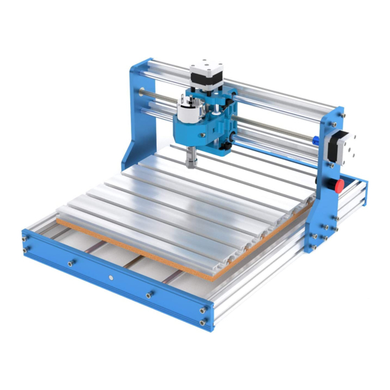
Seite 21: Übersicht Zur Montage
Installation Übersicht zur Montage... - Seite 22 Copyright © 2021 by SainSmart All rights reserved. This manual or any portion thereof may not be reproduced or used in any manner whatsoever without the written permission of the publisher, except for the use of brief quotations embodied in critical reviews and certain other noncommercial uses permitted by copyright law. For permission requests, write to the publisher.
- Seite 23 Genmitsu Desktop CNC & Laser www.sainsmart.com support@sainsmart.com Vastmind LLC, 5892 Losee Rd Ste. 132, N. Las Vegas, NV 89081...