Herunterladen Inhalt Inhalt Diese Seite drucken
HMS DWL2503 Bedienungsanleitung

HMS DWL2503 Bedienungsanleitung

Multifunktionale sprossenwand mit der hantelbank

Werbung

Verfügbare Sprachen

Verfügbare Sprachen

DRABINKA WIELOFUNKCYJNA Z ŁAWKĄ -
MULTIFUNCTIONAL LADDER WITH BENCH - VARIABILNÍ
POSILOVACÍ STANOVIŠTĚ – MULTIFUNKTIONALE
SPROSSENWAND MIT DER HANTELBANK
DWL2503
INSTRUKCJA UŻYTKOWANIA – MANUAL INSTRUCTION – NÁVOD
K OBSLUZE – BEDIENUNGSANLEITUNG

Werbung

Inhaltsverzeichnis
loading

Inhaltszusammenfassung für HMS DWL2503

  • Seite 1 DRABINKA WIELOFUNKCYJNA Z ŁAWKĄ - MULTIFUNCTIONAL LADDER WITH BENCH - VARIABILNÍ POSILOVACÍ STANOVIŠTĚ – MULTIFUNKTIONALE SPROSSENWAND MIT DER HANTELBANK DWL2503 INSTRUKCJA UŻYTKOWANIA – MANUAL INSTRUCTION – NÁVOD K OBSLUZE – BEDIENUNGSANLEITUNG...
  • Seite 2 UWAGI DOTYCZĄCE BEZPIECZEŃSTWA Drogi Użytkowniku: Dziękujemy za wybranie naszego produktu. Przed rozpoczęciem użytkowania przeczytaj uważnie instrukcję. Przed montażem i rozpoczęciem użytkowania urządzenia należy zapoznać się z poniższymi zaleceniami: Przed montażem należy trzymać się ściśle instrukcji: Aby zapewnić bezpieczeństwo, przed każdym użyciem należy sprawdzić, czy wszystkie śruby i inne elementy łączące są...
  • Seite 3 Części składowe zestawu treningowego: Part 1: Drabinka gimnastyczna Part 2: Drążek do podciągania Part 3: Poręcz Part 4: Ławka ** Przed montażem wyjmij wszystkie części z kartonów, w tym zestawy śrub montażowych.
  • Seite 4 ISTRUKCJA MONTAŻU: CZĘŚC 1: Drabinka gimnastyczna **Lista części: Części żelazne Opis Ilość Rama Szczebel Łącznik T-kształtny Łącznik żelazny Śruby Opis Ilość Śruba Śruba podsadzana i podkładka Śruba rozprężna Nylonowa nakrętka **Montaż krok po kroku: KROK 1: Przymocuj szczeble do ramy przy pomocy śruby podsadzanej i podkładki.
  • Seite 5 KROK 2: Przymocuj część dolną i górną za pomocą łączników żelaznych i śrub, również z drugiej strony. KROK 3: Umieść łączniki T-kształtne w ramach i dokręć pomocą nakrętek nylonowych. KROK 4: Przymocuj drabinkę do ściany za pomocą śrub rozprężnych; dokręć śruby.
  • Seite 6 Śruby Opis Ilość Śruba Śruba podsadzana i podkładka **Montaż krok po kroku: KROK 1: Przymocuj rurę żelazną za pomocą śrub podsadzanych i podkładek. KROK 2: Przymocuj wspornik trójkątny lewy i wspornik trójkątny prawy za pomocą śrub.
  • Seite 7 CZĘŚĆ 3: Poręcz **Lista części: Części żelazne Opis Ilość Wspornik trójkątny lewy Wspornik trójkątny prawy Rura łącząca 1 Rura łącząca 2 Uchwyt 1 Uchwyt 2 Podkładka pod łokieć Podkładka pod plecy Ś ruby Opis Ilość Śruba Śruba podsadzana i podkładka Śruba podsadzana Śruba podsadzana...
  • Seite 8 **Montaż krok po kroku: KROK 1: Przymocuj wspornik trójkątny lewy i wspornik trójkątny prawy oraz rurę łączącą 1 i rurę łączącą 2 za pomocą śruby podsadzanej i podkładki. KROK 2: Przymocuj uchwyty (1,2) za pomocą śrub (1). KROK 3: Przymocuj podkładkę...
  • Seite 9 Część 4: Ławka **Lista części: Iron Parts Opis Ilość Korpus główny Uchwyt Uchwyt piankowy Śruby Opis Ilość Śruba Pokrętło **Montaż krok po kroku: KROK 1: Przełóż uchwyt przez środkowy otwór korpusu głównego i nałóż na niego piankę, a następnie przykręć za pomocą...
  • Seite 10 KROK 2: Zamocuj uchwyt i uchwyt piankowy za pomocą śruby.
  • Seite 11 IMPORTANT SAFETY INFORMATION Dear Users: Thank you for choosing our product. Please read this instruction carefully before use Please note the following before installing and using the equipment: Before installation, strictly follow the instructions; To ensure the safety, before each use check whether all the bolts and other connecting parts of the equipment are locked;...
  • Seite 12 Including Parts of the whole training Set: Part 1:Supporting Bracket on the wall Part 2:Chin-Up Bar Part 3:Push-Up Bar Part 4:Sit Up Bench Before assemble take out all the parts from the cartons, including the screws sets for assemble easily.
  • Seite 13: Assembly Instruction

    ASSEMBLY INSTRUCTION: PART 1:Supporting Bracket on the wall **Part list: Iron Parts Description Supprting Bar Cross Bar “T” Shape Links Iron Connect sheet Screws Description Key Head Bolt Carriage Bolt and washer Expansion Screw Nylock Nut **Assemble Steps: STEP 1: Connect the Support bars, Cross Bars with Carriage Bolts and Washers.
  • Seite 14 STEP 2: Connect the Lower Section and Upper Section with Iron Connect sheets and Head Bolts, including another side. STEP 3: Put “T” Shape Links on the Support Bars and Tighter with The Nylon Nuts. STEP 4: Fix the Supporting Bracket on the wall with Expansion Screws and tighten the screws.
  • Seite 15 Screws Description Key Head Bolts Carriage Bolt and washer **Assemble Steps: STEP 1: Use Carriage Bolts and Washers to connect the Iron Tube. STEP 2: Use Key head Bolts to connect the left & right Lower Triangular Support.
  • Seite 16 PART 3:Push-Up Bar **Part list: Iron Parts Description Left Triangular Support Right Triangular Support Connect Tubes 1 Connect Tubes 2 Grab Bar 1 Grab Bar 2 Elbow Pad Back Pad Screws Description Key Head Bolt Carriage Bolt and washer Carrigage Bolt Carrigage Bolt...
  • Seite 17 **Assemble Steps: STEP 1: Use Carriage Bolt and Washer to connect the Lefit & Right Triangular Support and Connect Tubes 1, 2. STEP 2: Use Key head Bolts to connect the Grab Bar 1, 2. STEP 3: Use Carriage Bolts to connect the Elbow Pads and Back Pad.
  • Seite 18 Part 4:Sit Up Bench **Part list: Iron Parts Description Main Body Leg Tube Leg Foam Screws Description Key Head Bolt Knob...
  • Seite 19 **Assemble Steps: STEP 1: Let the Leg Tube through the middle hole of Main Body and Put Leg Foam on it and then screw it with the Knob. STEP 2: Use Key Head Bolts to Lock the Leg Tube and Foam Parts.
  • Seite 20 BEZPEČNOSTNÍ POKYNY Vážený uživateli: Děkujeme, že jste si vybrali náš produkt. Před použitím si pozorně přečtěte tento návod. Před instalací a používáním produktu se prosím seznamte s následujícím: 1. Montáž provádějte přesně podle instrukcí v tomto návodu; 2. Pro zajištění bezpečnosti uživatele zkontrolujte před každým tréninkem, zda jsou všechny šrouby a ostatní spojení...
  • Seite 21 Sestava obsahuje tyto části: Část 1: Žebřiny Část 2: Hrazda Část 3: Bradla Část 4: Lavice Před montáží vyjměte všechny díly z obalů, rozložte je na podlahu a zkontrolujte, že nic neschází.
  • Seite 22 Montáž: ČÁST 1: ŽEBŘINY **Seznam dílů: Ocelové části Č. Popis Konstrukce Příčka Výložník Spojka Spojovací materiál Č. Popis Spojovací šroub Šroub k příčce Kotva do zdi Nylonová matice **Postup montáže: KROK 1: Vyskládejte konstrukci podle obrázku, vložte do ní příčky a spojte pomocí šroubů...
  • Seite 23 KROK 2: Přiložte k sobě dolní a spodní část. Každou stranu spojte pomocí výložníku, na který nasunete spojku (destičku). Výložník vložte do otvoru ve spoji. Přiložte druhou spojku (destičku) a spojte pomocí 2 kompletních šroubů a nylonové matice. KROK 3: konstrukce vložte výložníky a...
  • Seite 24 ČÁST 2: Hrazda **Seznam dílů: Ocelové části Č. Popis Hrazda Montážní profil Pravá podpěra Levá podpěra Montážní materiál Č. Popis Imbusový šroub Šestihranný šroub...
  • Seite 25 **Postup montáže: KROK 1: Spojte montážní profil s hrazdou pomocí metrických šroubů. KROK 2: Hrazdu spojte s podpěrami pomocí imbusových šroubů. ČÁST 3: Bradla **Seznam dílů: Ocelové části Č. Popis Levá vzpěra Pravá vzpěra Spojovací díl 1 Spojovací díl 2 Horní...
  • Seite 26 Montážní materiál Č. Popis Šroub k madlu Šroub ke spojce Šroub k loketní opěrce Šroub k zádové opěrce **Postup montáže: KROK 1: Pravou a levou vzpěru spojte pomocí spojovacích dílů za pomocí šroubů č. 2. KROK 2: Madla připevněte pomocí šroubů č. 1. KROK 3: Opěrky připevněte pomocí...
  • Seite 27 Část 4: Lavice **Seznam dílů: Ocelové části Č. Popis Hlavní rám Noha Pěnové válce Montážní materiál Č. Popis Imbusový šroub Matice...
  • Seite 28 **Postup montáže: KROK 1: Závitnici nohy prostrčte ze spodní strany prostředním otvorem v hlavním rámu. Z horní strany nasaďte na závitnici pěnové válce. KROK 2: Díly spojte pomocí imbusových šroubů. Pěnové válce připevněte pomocí matice.
  • Seite 29 Sicherheitsanmerkungen Lieber Benutzer, Liebe Benutzerin: Vielen Dank, dass Sie sich für unser Produkt entschieden haben. Lesen Sie vor dem Beginn der Benutzung diese Bedienungsanleitung sorgfältig durch. Bitte beachten Sie folgende Anmerkungen, bevor Sie das Gerät montieren und benutzen: 1. Befolgen Sie streng vor der Montage die unten stehenden Anweisungen: 2.
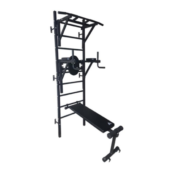
  • Seite 30 Bestandteile des Trainingssets: Teil 1: Sprossenwand Teil 2: Klimmzugstange Teil 3: Barren für Dips Teil 4: Hantelbank ** Nehmen Sie vor der Montage alle Bestandteile aus den Verpackungen inkl. des Sets mit den Montageschrauben heraus.
  • Seite 31 MONTAGEANLEITUNG: TEIL 1: Sprossenwand **Liste der Teile: Teile aus Eisen Beschreibung Menge Rahmen Sprosse Verbindungselement in der T-Form Verbindungselement aus Eisen Schrauben Beschreibung Menge Schraube Schlossschraube und Unterlegscheibe Spreizdübel Nylonmutter **Montage Schritt für Schritt: Schritt 1: Befestigen Sie die Sprossen am Rahmen mittels Schlossschrauben und Unterlegscheiben.
  • Seite 32 SCHRITT 2: Montieren Sie den unteren und oberen Teil mittels Verbindungselemente aus Eisen und Schrauben, beiderseits der Sprossenwand. SCHRITT 3: Befestigen Sie die Verbindungselemente in der T-Form am Rahmen. Ziehen Sie sie mittels Nylonmutter an. SCHRITT 4: Befestigen Sie die Sprossenwand an der Wand mittels Spreizdübel.
  • Seite 33 Schrauben Beschreibung Menge Schraube Schlossschraube Unterlegscheibe ** Montage Schritt für Schritt: SCHRITT 1: Befestigen Sie das Verbindungsrohr mittels Schlossschrauben und Unterlegscheiben. SCHRITT 2: Montieren Sie die dreieckigen Halterungen (rechts und links) mittels Schrauben.
  • Seite 34: Teil 3: Barren Für Dips

    TEIL 3: Barren für Dips **Liste der Teile: Teile aus Eisen Beschreibung Menge dreieckige Halterung, links dreieckige Halterung, rechts Verbindungsrohr 1 Verbindungsrohr 2 Griff 1 Griff 2 Lehne für Ellenbogen Rückenlehne Schrauben Beschreibung Menge Schraube Schlossschraube Unterlegscheibe Schlossschraube Schlossschraube...
  • Seite 35 ** Montage Schritt für Schritt: SCHRITT 1: Befestigen Sie die dreieckigen Halterungen (rechts und links) sowie beide Verbindungsrohre (1 und 2) mittels Schlossschrauben und Unterlegscheiben. SCHRITT 2: Montieren Sie die Griffe (1,2) mittels Schrauben (1). SCHRITT 3: Befestigen Sie die Lehne für Ellenbogen und Rücken mittels Schlossschrauben.
  • Seite 36 Schrauben Beschreibung Menge Schrauben Drehknopf **Montage Schritt für Schritt: SCHRITT 1: Führen Sie den Griff durch die mittlere Öffnung der Rückenlehne ein. Bringen Sie die Rollen aus Schaumstoff an. Drehen Sie alles mittels Drehknopfs SCHRITT 2: Befestigen Sie den Griff und Rollen aus Schaumstoff mittels Schrauben.
  • Seite 37: Warunki Gwarancji

    KARTA GWARANCYJNA Nazwa artykułu: Kod EAN: Data sprzedaży: WARUNKI GWARANCJI 1. Sprzedawca w imieniu Gwaranta udziela gwarancji na terytorium RP na okres 24 miesięcy od daty sprzedaży. 2. Gwarancja będzie respektowana przez sklep lub serwis po przedstawieniu przez klienta: czytelnie i poprawnie wypełnionej karty gwarancyjnej z pieczątką sprzedaży oraz podpisem sprzedawcy ważnego dowodu zakupu sprzętu z datą...
  • Seite 38 GUARANTEE CARD Article name: EAN code: Date of sale: GUARANTEE TERMS The Seller provides guarantee on behalf of the Guarantor within the territory of the Republic of Poland for the period of 24 months from the date of sale. The Guarantee will be recognised by the shop or service centre after the client provides: - clearly and correctly filled-in guarantee card with the sale stamp and the seller’s signature - valid purchase confirmation for the equipment including the date of sale / bill / -...
  • Seite 39 ZÁRUČNÍ LIST Název produktu: EAN kód: Datum prodeje: ZÁRUČNÍ PODMÍNKY skútr 24 měsíců. Prodávající jménem Ručitele poskytuje záruku na území Polska po dobu 24 měsíců od data prodeje: Záruka bude respektována obchodem nebo servisem po předložení zákazníkem: čitelně a správně vyplněného záručního listu s razítkem a podpisem prodávajícího platného doklad o koupi produktu s datem prodeje (účtu) reklamovaného produktu Jakékoli závady a poškození...
  • Seite 40: Garantiebedingungen

    GARANTIEKARTE Artikelname: EAN-Code: Verkaufsdatum: GARANTIEBEDINGUNGEN 3. Der Verkäufer gewährt im Namen des Garanten eine Garantie für 24 Monate nach dem Verkaufsdatum auf dem Hoheitsgebiet der Republik Polen. 4. Die Garantie wird von dem Laden oder dem Service nach Vorlage: der leserlich und korrekt ausgefüllten Garantiekarte mit Verkaufsstempel und Unterschrift des Verkäufers eines gültigen Kaufnachweises für das Gerät mit dem Verkaufsdatum / Rechnung/ der beanstandeten Ware...
  • Seite 41 IMPORTER: ABISAL SP. .Z.O.O., ul. Świętej Elżbiety 6, 41-905 Bytom Service: Pyskowicka 14, 41- 807 Zabrze abisal@abisal.pl www.abisal.pl...

Inhaltsverzeichnis