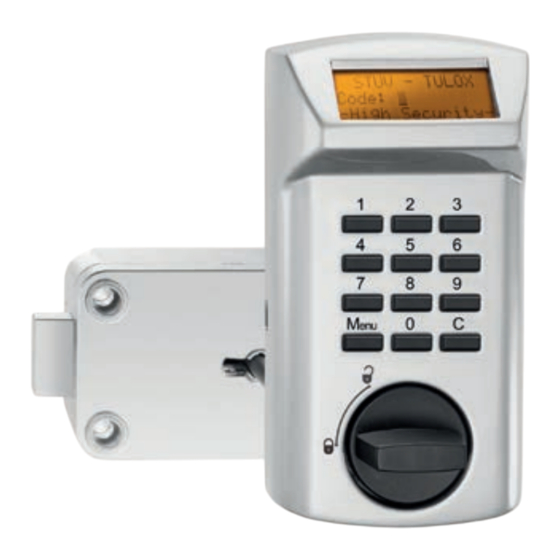
Stûv TULOX 100 Montageanleitung
Hochsicherheitsschlösser
Vorschau ausblenden
Andere Handbücher für TULOX 100:
- Benutzerhandbuch (32 Seiten) ,
- Bedienungsanleitung (5 Seiten) ,
- Benutzerhandbuch (16 Seiten)
Werbung
Verfügbare Sprachen
Verfügbare Sprachen
Quicklinks
TULOX 100
www.stuv.de
DE
•
Montageanleitung
EN
•
Installation Instructions
Nähere Informationen zur Bedienung fi nden Sie in der gesonderten Bedienungsanleitung
Please refer to the instruction manual for detailed information about the operation
TULOX 200
Werbung

Verwandte Anleitungen für Stûv TULOX 100


Inhaltszusammenfassung für Stûv TULOX 100
- Seite 1 TULOX 100 TULOX 200 www.stuv.de • Montageanleitung • Installation Instructions Nähere Informationen zur Bedienung fi nden Sie in der gesonderten Bedienungsanleitung Please refer to the instruction manual for detailed information about the operation...
- Seite 2 Montageanleitung TULOX 100 + 200 Inhalt Verwendung, Grundsätzliches Technische Hinweise Montageablauf, Variante 1 Montageablauf, Variante 2 Zeichnung Einbausituation TULOX 100 Zeichnung Einbausituation TULOX 200 Verwendung STUV - Produkte sind für höchste Anforderungen und größtmögliche Zuverlässigkeit konstruiert. Anwendungs- und Einbauempfehlungen sowie unsere umfangreiche Beratung unter- stützen Sie bei der Auswahl unserer Produkte.
- Seite 3 Montageanleitung TULOX 100 + 200 Montageanleitung TULOX 100 + 200 Technische Hinweise: Riegelkopfabmessungen 25,4 mm x 8,3 mm x 10,0 mm Riegelhub 10,0 mm Befestigungsschrauben 3 Zylinderschrauben DIN EN ISO 4762 - M6 x 35 mm - 8.8 Alternativ: 3 Zylinderschrauben BSW ¼“ x 35 mm...
- Seite 4 Montageanleitung TULOX 100 + 200 Bild 1 Notwendige Montagehöhe 37 mm Schlüsselloch Montageablauf Variante 1 Wenn Sie das Kabel durch eine separate Bohrung in den Innenraum des Wertbehältnisses führen, müssen Sie hierfür eine geeignete Bohrposition festlegen, die den VdS-Richtlinien entspricht.
- Seite 5 Montageanleitung TULOX 100 + 200 Bild 2 Achten Sie darauf, dass das Kabel um den Schrauben- kopf gelegt wird und nicht eingeklemmt werden kann. Die Sperrrichtung des Schlosses kann der erforderlichen Einbausituation angepasst werden. Hierzu werden die Feder und das Zahnrad aus der Grundplatte entfernt. Das Zahnrad kann jetzt in 90° - Schritten in die gewünschte Position gedreht und beide Teile wieder montiert werden (Bild 3).
- Seite 6 Montageanleitung TULOX 100 + 200 Schrauben Sie das Schloss mit 3 Zylinderkopfschrauben M6 x 35 oder BSW ¼“ x 35 fest an. Hierbei ist das Muttergewinde des Riegelwerks zu beachten. Die Schrauben müssen sich von Hand leicht ansetzen lassen. Führen Sie das Kabel durch die von Ihnen ausgeführte Bohrung in der Wertbehältnistür und stecken Sie den Kabelstecker auf der Rückseite des Schlosskastens in die dafür vorgesehene...
- Seite 7 Montageanleitung TULOX 100 + 200 Variante 2 Wenn Sie das Kabel durch die Achse führen, halten Sie bitte den nachfolgenden Ablauf ein. Schrauben Sie das Schloss mit 3 Zylinderkopfschrauben M6 x 35 oder BSW ¼“ x 35 fest an. Hierbei ist das Muttergewinde des Riegelwerks zu beachten. Die Schrauben müssen sich von Hand leicht ansetzen lassen.
- Seite 8 Montageanleitung TULOX 100 + 200 Richten Sie die Grundplatte senkrecht aus und markieren Sie die Bohrpunkte für die Befesti- gungsbohrungen. Nehmen Sie die Grundplatte wieder vollständig ab und bohren Sie die Befestigungsbohrungen mit einem Spiralbohrer Ø 3,5 mm. Eine Verschmutzung der Grundplatte durch Bohrspäne ist unbedingt zu vermeiden.
- Seite 9 Installation Instructions TULOX 100 + 200 Content Application, Basics Installation procedure, Version 1 Installation procedure, Version 2 Installation drawing TULOX 100 Installation drawing TULOX 200 Steinbach & Vollmann GmbH & Co. KG • 42579 Heiligenhaus - 09 -...
- Seite 10 Installation Instructions TULOX 100 + 200 Application STUV - Products are designed for highest demands and maximum reliability. Application and installation recommendations and our comprehensive consulting service provide support for the choice of our products. STUV - High security locks of the 4.17.10 series are intended for use on doors of secure storage units.
- Seite 11 Installation Instructions TULOX 100 + 200 Figure 1 Necessary assembly height 37 mm Key hole The ease of movement of the bolt in locking mode must be guaranteed. When using bars, angles or similar blocking elements attached to the bolt, transverse forces, resp. friction on the lock bolt must be avoided through construction measures.
- Seite 12 Installation Instructions TULOX 100 + 200 Figure 2 Pay attention that the cable is positioned around the screw head and cannot be jammed. The locking direction of the lock can be adjusted to the required installation situation. The spring and the cogwheel must be removed from the base plate for this purpose. The cogwheel can now be turned in the desired position in 90°...
- Seite 13 Installation Instructions TULOX 100 + 200 Screw the lock on tightly with 3 cylinder head screws M6 x 35 mm or BSW ¼“ x 35 mm. Consider the female thread of the bolt work. The insertion of the screws must be without force.
- Seite 14 Installation Instructions TULOX 100 + 200 Version 2 If you wish to lead the cable through the axis, please follow the sequence described below. Screw the lock on tightly with 3 cylinder head screws M6 x 35 mm or BSW ¼“ x 35 mm.
- Seite 15 Installation Instructions TULOX 100 + 200 Align the base plate vertically and mark the drilling position for the fastening screws. Completely remove the base plate again and drill the fastening holes with a spiral drill Ø 3.5 mm. Pay careful attention that the base plate is not contaminated with bore chips.
-
Seite 16: Anhang / Appendix
Anhang / Appendix Mittelpunkt Achse = Mittelpunkt Schlüsselloch axis centre = keyhole centre - 16 - Steinbach & Vollmann GmbH & Co. KG • 42579 Heiligenhaus... - Seite 17 Anhang / Appendix Steinbach & Vollmann GmbH & Co. KG • 42579 Heiligenhaus - 17 -...
- Seite 18 Anhang / Appendix Mittelpunkt Achse = Mittelpunkt Schlüsselloch axis centre = keyhole centre - 18 - Steinbach & Vollmann GmbH & Co. KG • 42579 Heiligenhaus...
- Seite 19 Anhang / Appendix Steinbach & Vollmann GmbH & Co. KG • 42579 Heiligenhaus - 19 -...
- Seite 20 Parkstraße 11 42579 Heiligenhaus Germany Telefon +49 2056 14-0 Telefax +49 2056 14-251 E-Mail info@stuv.de Internet www.stuv.de 04/2015 Printed in Germany. Zumutbare Abweichungen in Model- len und Farben sowie Änderungen zur Anpassung an den neuesten Stand der Technik und Produktion...