Inhaltsverzeichnis
Werbung
Verfügbare Sprachen
Verfügbare Sprachen
Quicklinks
Installations- und Betriebsanleitung
BY
Servicehandbuch
Modell: WQ(D), WQK, WVS(D), WQ-QG
Vor der Inbetriebnahme sicherstellen, dass die Pumpe geerdet ist.
Prüfen, ob der Fehlerstromschutzschalter ordnungsgemäß angebracht ist.
Warnung
Die elektrische Pumpe nicht berühren, während sie in Betrieb ist.
Die elektrische Pumpe nicht ohne Wasser betreiben.
Werbung
Kapitel
Inhaltsverzeichnis
Fehlerbehebung

Verwandte Anleitungen für WITA ADELINO WQD-Serie


Inhaltszusammenfassung für WITA ADELINO WQD-Serie
- Seite 1 Installations- und Betriebsanleitung Servicehandbuch Modell: WQ(D), WQK, WVS(D), WQ-QG Vor der Inbetriebnahme sicherstellen, dass die Pumpe geerdet ist. Prüfen, ob der Fehlerstromschutzschalter ordnungsgemäß angebracht ist. Warnung Die elektrische Pumpe nicht berühren, während sie in Betrieb ist. Die elektrische Pumpe nicht ohne Wasser betreiben.
-
Seite 2: Eg-Konformitätserklärung
EG-Konformitätserklärung Name des Ausstellers: WITA Sp. z o. o. 86-005 Białe Błota Zielonka, ul. Biznesowa 22 Polen Gegenstand der Erklärung Adelino-Abwasserpumpe Design: WQD..., WQ..., WQD...L3, WQD...L1, WQ...L3, WQ...L1, WQD...X, WQ...X, WQK..., WVSD..., WVS..., ...WQD... QG, ...WQ..QG Wir erklären in alleiniger Verantwortung, dass die oben angegebenen Produkte, auf die sich diese EG-Konformitätserklärung bezieht, den folgenden Normen und Richtlinien entsprechen:... -
Seite 3: Inhaltsverzeichnis
Inhalt 1. Produktinformationen • • • • • • • • • • • • • • • • • • • • • • • • • • • • • • • • • • • • • • • • • • • • • • • • • • • 2. -
Seite 4: Warnung Für Kinder Und Personen Mit Einschränkungen
Vielen Dank, dass Sie sich für unser Produkt entschieden haben. Lesen Sie sich diese Anleitung vor der Installation und Verwendung bitte aufmerksam durch und bewahren Sie sie sorgfältig auf. Bei Installation und Betrieb müssen die örtlichen Bestimmungen eingehalten werden. Unsachgemäße Verwendung kann zu Personenschäden führen. •... -
Seite 5: Weist Darauf Hin, Dass Die Entsprechenden Vorschriften Eingehalten Werden Müssen
Weist darauf hin, dass Berühren verboten ist, und Nichtbeachtung zum Tod oder zu schweren Verletzungen führt Weist darauf hin, dass die entsprechenden Vorschriften eingehalten werden müssen Weist auf verbotene Handlungen hin, die nicht ausgeführt werden dürfen oder beendet werden müssen Weist auf das Symbol des Schutzleiters zum Schutz vor Stromschlag hin Erklärung Gefahren oder Schäden, die durch eine der nachfolgend aufgeführten Umstände infolge von... -
Seite 6: Produktinformationen
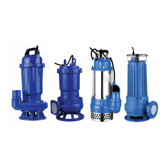
1. Produktinformationen 1.1 Anwendungen der Pumpe Die elektrischen Pumpen WQ(D), WQ(m), WQK, WVSD, WQ(D)-QG sind Abwassertauchpumpen (nachfolgend als „elektrische Pumpen“ bezeichnet). Die elektrischen Pumpen dieser Serie finden verbreitet Einsatz in Industrie, Landwirtschaft, Bergbau, Bausektor und Kommunalverwaltung sowie Umweltschutz. Die flüssigen Medien können Fasern, Papierstücke und weitere feste Bestandteile oder weiche Feststoffe, z. -
Seite 7: Anschlussplan Der Pumpe
1.4 Anschlussplan der Pumpe In den folgenden Abbildungen wird die interne Verkabelung der elektrischen Pumpen dargestellt. U V W Schwim- merschalter Kondensator Einphasig Dreiphasig Bei der Verdrahtung der elektrischen Pumpe muss ein Fehlerstromschutzschalter installiert werden und der gelb-grüne Draht mit Erdungskennzeichnung im abgehenden Kabel muss sicher geerdet werden. Bei elektrischen Pumpen, die bei Lieferung mit Stecker ausgestattet sind, muss die passende Steckschalttafel sicher geerdet werden. -
Seite 8: Technische Daten
2. Technische Daten Die folgende Tabelle enthält die technischen Daten der elektrischen Pumpen der Serien WQ(D), WQK, WVSD und WQ(D)-QG. Max. Max. Förderhö- Fest- Spannung Strom Leistung Auslauf Durchfluss Förderhöhe henbereich stoffdurchlass Modell (kW) (mm) (m³/h) (mm) WQD6-12-0.55 0,55 0–14 WQD6-16-0.75 0,75 5–18... - Seite 9 Max. Max. Förderhö- Fest- Spannung Strom Leistung Auslauf Modell Durchfluss Förderhöhe henbereich stoffdurchlass (kW) (mm) (m³/h) (mm) WQ150-20-18.5 36,7 18,5 0–28 WQ180-20-18.5 36,7 18,5 0–28 WQ250-15-18.5 36,7 18,5 0–22 WQ350-10-18.5 36,7 18,5 0–17 3 × 400 V, WQ100-37-22 42,7 25–44 50 Hz 4-polig WQ130-30-22 42,7...
- Seite 10 Max. Max. Förderhö- Fest- Spannung Strom Leistung Auslauf Durchfluss Förderhöhe henbereich stoffdurchlass Modell (kW) (mm) (m³/h) (mm) WQK9.6-10-0.75 0,75 8–12 WQK15-12-1.5 9–15 WQK18-15-2.2 12–18 3 × 400 V, 50 Hz 2-polig WQK30-18-3.7 14–22 WQK36-22-5.5 11,1 17–27 WQK48-25-7.5 14,9 20–30 WVSD55 0,55 5–9 WVSD75...
-
Seite 11: Installationsanleitung
3. Installationsanleitung 3.1 Maßnahmen vor der Installation 1. Die elektrische Pumpe vor der Installation und Verwendung vollständig auf Transport- oder Lagerungsschäden überprüfen, z. B. sicherstellen, dass sich Kabel in einwandfreiem Zustand befinden. Wird ein Schaden festgestellt, ist das betreffende Teil von einer Fachkraft auszutauschen oder zu reparieren. -
Seite 12: Empfohlene Zusätzliche Vorkehrungen
3. Während die elektrische Pumpe in Betrieb ist, muss ein Warnschild mit einer Aufschrift wie „Stromschlaggefahr; Zutritt Stromschlaggefahr; verboten“ am Arbeitsort angebracht werden, um Unfälle zu kein vermeiden. Zutritt 3.4 Empfohlene zusätzliche Vorkehrungen 1. Bei einphasigen elektrischen Pumpen mit integriertem Thermoschalter mit automatischem Reset erfolgt das Zurücksetzen automatisch, wenn die Motortemperatur auf einen bestimmten Wert absinkt. - Seite 13 Tabelle 2: Kabelanschlussschema Schema Beschreibung 1. Isolierungsschicht entfernen, ohne den Leiter zu beschädigen. 2. Lange und kurze Kabel gestaffelt anordnen. 3. Sicherstellen, dass die Verbindung frei von Öl, Wasser und anderen Verunreinigungen ist. 1. Jeden Leiter gleichmäßig in mehrere Stränge aufteilen (mindestens 6 Stk.) und straffen.
-
Seite 14: Instandhaltung
4. Instandhaltung 1. Den Isolationswiderstand zwischen Gehäuse und Wicklung der elektrischen Pumpe regelmäßig kontrollieren. Er muss mindestens 1 MΩ betragen, wenn die Betriebstemperatur nahezu erreicht ist. Andernfalls muss der Betrieb der Pumpe unterbrochen werden, bis die entsprechenden Wartungsmaßnahmen durchgeführt wurden und die geltenden Anforderungen erfüllt sind. -
Seite 15: Problemlösung
5. Problemlösung Vor der Durchführung von Maßnahmen zur Problemlösung sicherstellen, dass die Pumpe ausgeschaltet ist und alle beweglichen Teile stillstehen. Pumpe gegen versehentliches Wiedereinschalten sichern. Störung Ursache Behebung 1. Die Versorgungsspannung ist zu niedrig. 1. Spannung auf ±10 % des Nennwerts einstellen 2. -
Seite 16: Anhang
Anhang 7. Anhang Schmutzwassertauchpumpe WQ(D) US GPM Imp GPM Fuß n = 2850 U/min Förderstrom (I/min) Förderstrom (m³/h) US GPM Imp GPM Fuß n = 2850 U/min Förderstrom (I/min) Förderstrom (m³/h) US GPM Imp GPM Fuß n = 2850 U/min Förderstrom (I/min) Förderstrom... - Seite 17 Anhang Förderstrom (I/min) Förderstrom (m³/h) US GPM Imp GPM Fuß n = 2850 U/min Förderstrom (I/min) Förderstrom (m³/h) Schmutzwassertauchpumpe WQ US GPM Imp GPM Fuß n = 1450 U/min Förderstrom (I/min) Förderstrom (m³/h) US GPM Imp GPM Fuß n = 1450 U/min Förderstrom (I/min) Förderstrom...
- Seite 18 Anhang Abwassertauchpumpe WQ(D)-L US GPM Imp GPM Fuß WQD-L1 n = 2850 U/min Förderstrom (I/min) Förderstrom (m³/h) US GPM Imp GPM Fuß WQD-L1 n = 2850 U/min Förderstrom (I/min) Förderstrom (m³/h) US GPM Imp GPM Fuß WQD-L1 n = 2850 U/min Förderstrom (I/min) Förderstrom...
- Seite 19 Förderstrom Anhang (I/min) Förderstrom (m³/h) US GPM Imp GPM Fuß WQD-L1 n = 2850 U/min Förderstrom (I/min) Förderstrom (m³/h) US GPM Imp GPM Fuß WQ(D)-X n = 2850 U/min Förderstrom (I/min) Förderstrom (m³/h) Abwassertauchpumpe WQK US GPM Imp GPM Fuß n = 2850 U/min Förderstrom (I/min) Förderstrom (m³/h)
- Seite 20 Anhang Abwassertauchpumpe WVS(D) US GPM Imp GPM Fuß WVSD n = 2850 U/min Förderstrom (I/min) Förderstrom (m³/h) US GPM Imp GPM Fuß WVSD n = 2850 U/min Förderstrom (I/min) Förderstrom (m³/h) Abwassertauchpumpe WQ-QG US GPM Imp GPM Fuß WQ-QG n = 2850 U/min Förderstrom (I/min) Förderstrom (m³/h)
- Seite 23 Installation and operation instructions Service Manual Model: WQ(D), WQK, WVS(D), WQ-QG Make sure the electric pump is grounded before operation Check if leakage protection device is reliably equipped Warning Do not touch the electric pump while it is running Do not run electric pump without water...
-
Seite 24: Ec Declaration Of Conformity
EC Declaration of Conformity Name of the issuer: WITA Sp. z o. o. 86-005 Białe Błota Zielonka, ul. Biznesowa 22 Poland Subject of the declaration Adelino Sewage Pump Design: WQD..., WQ..., WQD...L3, WQD...L1, WQ...L3, WQ...L1, WQD...X, WQ...X, WQK..., WVSD..., WVS..., ...WQD...QG, ...WQ..QG... - Seite 25 Contents 1. Product Information • • • • • • • • • • • • • • • • • • • • • • • • • • • • • • • • • • • • • • • • • • • • • • • • • • • • • 2.
- Seite 26 Thank you very much for choosing our product. Please read through this instruction manual and keep it properly before installation and use. Installation and operation muss comply with local regulations. Improper use may lead to personal injuries. • Before operation, make sure that the electric pump is grounded reliably and leakage protection device is equipped •...
-
Seite 27: Indicates The Symbol Of Ground Wire In Case Of An Electric Shock
Indicates that touch is prohibited, which, if ignored, will result in death or serious personal injury Indicates that the relevant rules shall be observed Indicates prohibited actions, which must not be taken or must be stopped Indicates the symbol of ground wire in case of an electric shock Statement: Any hazard or loss caused by any of the following circumstances, where the content hereof is not observed, is not included in the scope of the manufacturer’s quality warranty:... -
Seite 28: Product Information
1. Product Information 1.1 Pump Applications The Submersible electric sewage pumps (hereinafter referred to as the “electric pumps”) include WQ(D), WQK, WVSD, WQ(D)-QG electric pumps. This series of electric pumps are widely used in the fields of industry, agriculture, mining, building construction, and municipal administration and environmental protection. - Seite 29 1.4 Pump Wiring Diagramm The following figures describe the internal wiring details of the electric pumps. U V W Float switch Capacitor Single phase Three phase At wiring, electric pumps should be correctly installed with electrical leakage protector, and a yellow-green wire attached with earthing mark in the outgoing cable of electric pump shall be earthed reliably.
-
Seite 30: Technical Parameters
2. Technical Parameter The following table describes the technical data of the electric pumps of WQ(D), WQK, WVSD, WQ(D)-QG series. Max. Max. Head Solids Voltage Current Power Discharge Model Flow Head Range Passage (mm) (kW) (m³/h) (mm) WQD6-12-0.55 0.55 0~14 WQD6-16-0.75 0.75 5~18... - Seite 31 Max. Max. Head Solids Voltage Current Power Discharge Model Flow Head Range Passage (kW) (mm) (m³/h) (mm) WQ150-20-18.5 36.7 18.5 0~28 WQ180-20-18.5 36.7 18.5 0~28 WQ250-15-18.5 36.7 18.5 0~22 WQ350-10-18.5 36.7 18.5 0~17 3 × 400V, 50Hz WQ100-37-22 42.7 25~44 4 Pole WQ130-30-22 42.7...
- Seite 32 Max. Max. Head Solids Voltage Current Power Discharge Model Flow Head Range Passage (mm) (kW) (m³/h) (mm) WQK9.6-10-0.75 0.75 8~12 WQK15-12-1.5 9~15 WQK18-15-2.2 12~18 3 × 400V, 50Hz 2 Pole WQK30-18-3.7 14~22 WQK36-22-5.5 11.1 17~27 WQK48-25-7.5 14.9 20~30 WVSD55 0.55 WVSD75 0.75 WVSD110...
-
Seite 33: Installation Instructions
3. Installation Instructions 3.1 Before Installation 1. Electric pumps shall be comprehensively checked for damage during transportation and storage prior to installation and use, e.g. whether cable is in good condition. In case of any damage, please have the replacement or repair carried out by a specialist. - Seite 34 3. When electric pump is running, the safety warning sign of “Shock hazard, no man or animal shall enter” shall be arranged Shock hazard, no at the work site to avoid accidents. man or animal shall enter 3.4 Additional recommended precations 1.
- Seite 35 Table 2: Cable wiring diagram Pos. Schematic diagram Description 1. Remove the insulating layer without damaging the conductor. 2. Stagger long and short wires. 3. Ensure that no oil, water or any other pollutant exists at the connection. 1. Divide each connector into several strands evenly (no less than 6 ones) and tighten them 2.
-
Seite 36: Mechanical Seal
4. Maintance 1. Regularly inspect the insulation resistance between the enclosure and the winding of the electric pump, which shall not be less than 1MΩ when the operating temperature is nearly achieved. Otherwise, the use of the pump shall not be allowed until the corresponding maintenance measures are taken and the relevant requirements are met. -
Seite 37: Troubleshooting
5. Troubleshooting Before performing any troubleshooting, make sure the pump has been turned off and all moving components have stopped rotating. Make sure that the pump cannot be turned on accidentally. Fault Cause Remedy 1. Adjust the voltage to ±10% of the rated value 1. -
Seite 38: Appendix
Appendix 7. Appendix WQ(D) Submersible Pump For Dirty Water... - Seite 39 Appendix WQ Submersible Pump For Dirty Water...
- Seite 40 Appendix WQ(D)-L Submersible Sewage Pump...
- Seite 41 Appendix WQK Submersible Sewage Pump...
- Seite 42 Appendix WVS(D) Submersible Sewage Pump WQ-QG Submersible Sewage Pump...
-
Seite 45: Instrukcja Montażu I Obsługi
Instrukcja montażu i obsługi Instrukcja obsługi Model: WQ(D), WQK, WVS(D), WQ-QG Przed rozpoczęciem eksploatacji upewnić się, czy pompa elektryczna jest uziemiona Sprawdzić, czy zabezpieczenie upływowe zostało należycie zamontowane Ostrzeżenie Nie dotykać pompy elektrycznej w trakcie pracy Nie uruchamiać pompy elektrycznej bez wody... -
Seite 46: Deklaracja Zgodności Ce
Deklaracja zgodności CE Dystrybutor: WITA Sp. z o.o. 86-005 Białe Błota Zielonka, ul. Biznesowa 22 Polska Przedmiot deklaracji: Pompa zanurzeniowa Adelino Model: WQD..., WQ..., WQD...L3, WQD...L1, WQ...L3, WQ...L1, WQD...X, WQ...X, WQK..., WVSD..., WVS..., ...WQD...QG, ...WQ..QG Z pełną odpowiedzialnością oświadczamy, że podane wyżej produkty, których dotyczy niniejsza Deklaracja Zgodności CE, spełniają... - Seite 47 Spis treści 1. Informacje o produkcie • • • • • • • • • • • • • • • • • • • • • • • • • • • • • • • • • • • • • • • • • • • • • • • • • • • 2.
- Seite 48 Dziękujemy za wybranie naszego produktu. Prosimy o przeczytanie niniejszej instrukcji i zachowanie jej na czas montażu i użytkowania. Montaż i obsługa muszą być przeprowadzone zgodne z niniejszą instrukcją oraz lokalnymi przepisami. Niewłaściwe użytkowanie może doprowadzić do obrażeń ciała. • Przed rozpoczęciem eksploatacji należy upewnić się, czy pompa elektryczna jest prawidłowo uziemiona i czy zamontowano zabezpieczenie upływowe •...
- Seite 49 Symbol ten oznacza, że obowiązuje zakaz dotykania, a jego złamanie prowadzi do śmierci lub poważnych uszkodzeń ciała. Symbol ten oznacza, że należy przestrzegać oznaczonych nim zasad. Symbol ten oznacza czynności zabronione, których nie wolno podejmować i które należy powstrzymywać. Symbol ten oznacza przewód uziemiający – na wypadek porażenia prądem elektrycznym.
-
Seite 50: Informacje O Produkcie
1. Informacje o produkcie 1.1 Zastosowania pompy Zanurzeniowe pompy elektryczne do brudnej wody obejmuję modele pomp elektrycznych WQ(D), WQK, WVSD, WQ(D)- QG. Pompy elektryczne z ww. serii są powszechnie stosowane w przemyśle, rolnictwie, górnictwie, budownictwie oraz administracji komunalnej i ochronie środowiska. Ciecze stanowiące medium mogą zawierać włókno, makulaturę i inne cząstki stałe lub miękkie ciała stałe, np. - Seite 51 1.4 Schemat instalacji elektrycznej pompy Następujące rysunki przedstawiają szczegóły wewnętrznej instalacji elektrycznej pomp elektrycznych. U V W Wył. pływakowy Kondensator 1 faza 3 fazy W pompach elektrycznych należy odpowiednio zamontować zabezpieczenie upływowe. Wymagane jest również właściwe uziemienie podłączonego żółto-zielonego przewodu z oznaczeniem uziemienia w przewodzie wyjściowym pompy elektrycznej.
-
Seite 52: Parametry Techniczne
2. Parametry techniczna Następująca tabela przedstawia dane techniczne dotyczące pomp elektrycznych z serii WQ(D), WQK, WVSD, WQ(D)-QG. Przepływ Maks. Maks. Zakres Średnica Napięcie Natężenie substancji przepływ podnoszenie pompowania przyłącza Model (kW) stałych (m³/h) (mm) (mm) WQD6-12-0.55 0.55 0~14 WQD6-16-0.75 0.75 5~18 1 ×... - Seite 53 Przepływ Maks. Maks. Zakres Średnica Napięcie Natężenie substancji Model przepływ podnoszenie pompowania przyłącza (kW) stałych (m³/h) (mm) (mm) WQ100-32-18.5 36.7 18.5 20~37 WQ150-20-18.5 36.7 18.5 0~28 WQ180-20-18.5 36.7 18.5 0~28 WQ250-15-18.5 36.7 18.5 0~22 WQ350-10-18.5 36.7 18.5 0~17 3 × 400V, 50Hz 4 biegunowe WQ100-37-22 42.7...
- Seite 54 Przepływ Maks. Maks. Zakres Średnica Napięcie Natężenie substancji Model przepływ podnoszenie pompowania przyłącza (kW) stałych (m³/h) (mm) (mm) WQ6-16-0.75X 0.75 9~17 WQ10-11-0.75X 0.75 0~16 WQ15-12-1.1X 0~16 WQK9.6-10-0.75 0.75 8~12 3 × 400V, 50Hz WQK15-12-1.5 9~15 2 biegunowe WQK18-15-2.2 12~18 WQK30-18-3.7 14~22 WQK36-22-5.5 11.1...
-
Seite 55: Instrukcje Montażu
3. Instrukcje montażu 3.1 Przystąpienie do montażu 1. Przed montażem i obsługą należy dokładnie sprawdzić, czy pompy elektryczne nie zostały uszkodzone podczas transportu lub przechowywania, np. czy przewód jest w dobrym stanie. W przypadku jakichkolwiek uszkodzeń należy zlecić wymianę lub naprawę... - Seite 56 wirnik przed zablokowaniem lub zapchaniem przez wodne rośliny lub gruz, co spowodowałoby nieprawidłowe działanie pompy elektrycznej. W trakcie pracy należy sprawdzać często poziom wody, aby uniknąć sytuacji, w której pompa elektryczna pracuje bez wody. 3. Podczas pracy pompy elektrycznej w miejscu pracy należy Niebezpieczeństwo umieścić...
- Seite 57 Table 2: Schemat łączenia przewodów Schemat Opis 1. Zdjąć warstwę izolacyjną, nie uszkadzając przy tym przewodu. 2. Ułożyć naprzemiennie przewody długie i krótkie. 3. Upewnić się, że na złączu nie ma żadnego oleju, wody lub innych zanieczyszczeń. 1. Rozdzielić każdy przewód na taką samą ilość żył (nie mniej niż 6) i spleść...
-
Seite 58: Konserwacja
4. Konserwacja 1. Należy regularnie sprawdzać rezystancję izolacji między obudową i uzwojeniem pompy elektrycznej, która nie może wynosić mniej niż 1MΩ w okolicach temperatury roboczej. W przeciwnym razie, używanie pompy nie będzie dozwolone do czasu podjęcia odpowiednich działań konserwacyjnych i spełnienia właściwych wymogów. Ostrzeżenie 2. -
Seite 59: Usuwanie Usterek
5. Usuwanie usterek Przed przystąpieniem do rozwiązywania jakichkolwiek problemów należy upewnić się, że pompa została wyłączona, a wszystkie ruchome elementy przestały się poruszać. Należy upewnić się, że pompa nie może zostać przypadkowo włączona. Awaria Przyczyna Rozwiązanie 1. Wyregulować napięcie do ±10% wartości znamionowej 1. -
Seite 60: Załącznik
Załącznik 7. Załącznik Pompa zanurzeniowa do wody brudnej WQ(D) - Seite 61 Załącznik Pompa zanurzeniowa do wody brudnej WQ...
- Seite 62 Załącznik Pompa zanurzeniowa do ścieków WQ(D)-L...
- Seite 63 Załącznik Pompa zanurzeniowa do ścieków WQK...
- Seite 64 Załącznik Pompa zanurzeniowa do ścieków WVS(D) Pompa zanurzeniowa do ścieków WQ-QG...