Purmo TempCo Basic 24V Montageanleitung
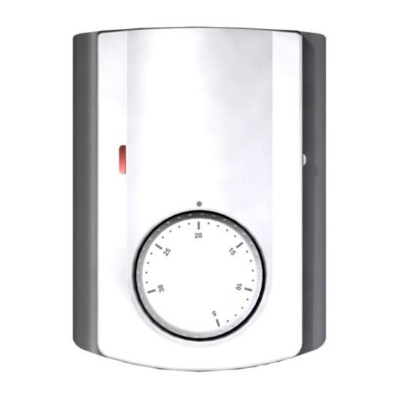
Analog raumthermostat
Vorschau ausblenden
Andere Handbücher für TempCo Basic 24V:
- Bedienungsanleitung (56 Seiten) ,
- Bedienungsanleitung
Verfügbare Sprachen
Verfügbare Sprachen
User Guide
UFH – 24VAC Analogic thermostat
-
-
-
-
Technical characteristics
Measured temperature precision
Operating temperature
Setting temperature range
Regulation characteristics
Electrical Protection
Power Supply
Consumption
Output
How to use your thermostat
Setting knob:
The thermostat will follow the setting temperature all the time.
LED Indicator
Red:
Heating indication.
Purmo DiaNorm Wärme AG
Lierestraße 68 38690 Vienenburg Germany
Tel: +49 5324 808-0
info@purmo.de
/
www.purmo.de
Wired Analogic thermostat (24VAC)
specially designed to control your Under
Floor Heating managed by actuator (NC).
Flush Mounting version, standard fixing
with 60mm axes.
Thermostat with silent output.
Can drive directly the actuators, or can
be connected to the UFH connecting
boxes range.
0.1°C
0°C - 50°C
5°C - 30°C
hysteresis (ON/OFF)
Class II - IP30
24VAC 50Hz
~ 0,5W
TRIAC
24VAC 15W Max
Rettig Heating Sp. z o.o.
ul. Przemysłowa, 44-203 Rybnik, Poland Biuro Handlowe
ul. Rotmistrza Pileckiego 91, 02-781 Warszawa, Poland
Tel: +48 22 643 25 20
Fax: +48 22 643 99 95
Fax: +49 5324 808-999
purmow@purmo.pl
/
www.purmo.pl
How to caliber and limit the setting range.
GB
If your thermostat needs to calibrated, make these operations:
1. Put a thermometer in the middle of the room at 1.5 Meter distance of the
floor.
2. Wait 1 hour to be sure that your thermostat shows the correct temperature.
3. Remove the setting button by pressing gently outwards with a narrow
screwdriver between the button and the cover. (pay attention to avoid
setting button rotation)
4. Remove the internal wheel from the button. (Figure 1)
5. Put the internal wheel alone on the thermostat. (Figure 2)
6. You can now put the setting button on the thermostat, while making
corresponds real room temperature (showed by the thermometer) and
thermostat indexer.
If your thermostat needs to be limited, make these operations:
1. Set the setting button on the middle of the new setting range.
2. Remove the setting button by pressing gently outwards with a narrow
screwdriver between the button and the cover.
3. Remove the dial pins and put in the desired holes to limit the setting range
of the thermostat. (Figure 3 et 4)
4. You can now put the setting button on the thermostat.
Fig. 3
Fig. 1
20°C
20°C
Fig. 4
Fig. 2
25°C
Max
Limitation
Min
Limitation
10°C
15°C
PPLIMP06664A

Verwandte Anleitungen für Purmo TempCo Basic 24V


Inhaltszusammenfassung für Purmo TempCo Basic 24V
- Seite 2 Kalibrierung und Begrenzung des Einstellbereiches Montage Anleitung Analog Raumthermostat 24 VAC Sollte eine Kallibrierung des Raumthermostaten erforderlich sein, gehen Sie wie folgt vor: 1. Messen Sie die Raumtemperatur in der gewünschten Aufenthaltszone ca. Analoger Raumthermostat 24VAC für 1,5 m über dem Boden elektrothermische Stellantriebe stromlos 2.