Werbung
Quicklinks
GEFAHR: Stromschlag und Verletzung durch offen liegende, spannungsführende Bauteile (230 V, 50 Hz)!
Vor Arbeiten an elektrischen Anlagen alle betroffenen Geräte von der Stromversorgung trennen. Kabel nicht unter Spannung berühren.
Anschluss des Netzteils nur von qualifi ziertem und geschultem Personal.
DANGER: Electric shock and injury due to exposed live components (230 V, 50 Hz)!
Before working on electrical installations, disconnect all affected equipment from the power supply. Connect and touch cables only in voltage-free state.
Installation of the cables must only be performed by qualified and trained personnel.
Dose montieren
Installing the surface mounted box
Benötigte Dosen / Required boxes:
- 1 Dose Aufputz für Bedieneinheit sMove und Verbindungsklemmen
- 1 Dose Aufputz mit Blindabdeckung für Unterputz-Schaltnetzteil
- 1 Surface mounted box for sMove controlling unit and terminal blocks
- 1 Surface mounted box with blanking cover for power supply unit
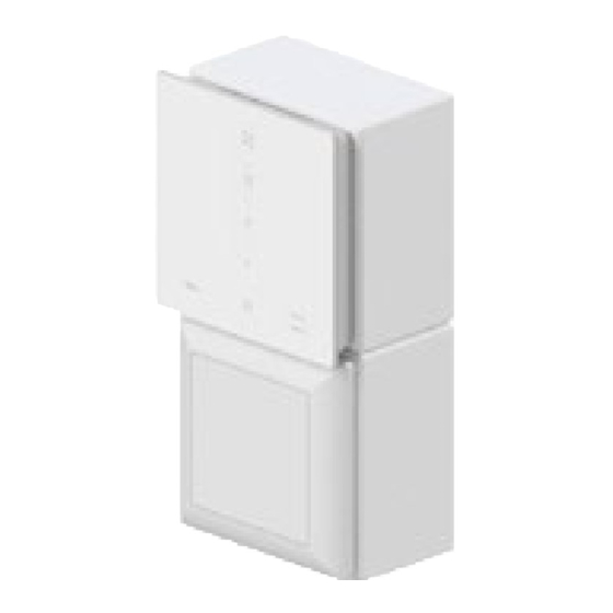
HINWEIS: Werden zwei Dosen ohne Abstand übereinander montiert,
muss das Schaltnetzteil in der unteren Dose montiert werden.
Zur Montage der Bedieneinheit wird Platz nach oben benötigt.
NOTICE: When mounting two boxes on top of each other without any
clearance between them, the PSU must be mounted inside the bottom box
to ensure the operating unit may be fitted properly.
1
Brechen Sie aus der Dose die Kabeldurchführungen entsprechend der baulichen
Begebenheiten heraus:
•
(oben angebrachte)
Dose für Bedieneinheit:
- Kabeldurchführung für Ventilator-BUS-Leitungen und optionale Sensorik
- Kabeldurchführung für das Betriebsspannungskabel
•
(unten angebrachte)
Dose mit Blindabdeckung:
- Kabeldurchführung für das Netzanschlusskabel
- Kabeldurchführung für das Betriebsspannungskabel
Break out the following cable entries according to your installation site from the box:
• (upper)
box for sMove operating unit:
- for the fan BUS and the optional sensor's cable.
- one for the operating voltage cable
(to bottom box)
• (bottom)
box with blanking cover:
- one cable entry for the power supply cable
- one for the operating voltage cable
(to upper box)
2
Verlegen Sie das Netzanschlusskabel (230 V, 50 Hz) in die Dose.
Verlegen Sie die Ventilator-BUS-Leitungen zwischen Lüftungsgerät und Dose.
Lay the power supply cable (230 V, 50 Hz) to the mounting location.
Lay the fan BUS between the ventilation device and the mounting location.
3
Verschrauben Sie die Aufputz-Dosen an der Innenwand.
Achten Sie darauf, dass sich die vormontierten Schrauben jeweils an der
rechten und linken Seite befi nden.
Secure the surface mounted boxes to the interior wall using rawl plugs and
fixing screws. Make sure, that the pre-assembled screws are pointing to the
right and left.
All manuals and user guides at all-guides.com
Unterputz-Schaltnetzteil anschließen
Connecting the switching PSU
1
1
Verbinden Sie das Eingangskabel Schaltnetzteil (blau/braun) über die Lüster-
klemme mit dem Netzanschlusskabel:
• Phase mit Leitung L verbinden (braun).
• Neutral-Leiter mit Leitung N verbinden (blau).
Connect the PSU's input cable (blue/brown) via a lustre terminal:
• Connect the phase conductor with cable L (brown).
• Connect the neutral conductor with cable N (blue).
2
Setzen Sie das Schaltnetzteil in die untere Dose ein. Verlegen Sie das Ausgangs-
kabel Netzteil (rot, + / schwarz, – ; entspricht Betriebsspannungkabel) durch die
erstellte Kabeldurchführung in die obere Dose.
Slide the connected PSU into the lower box. Feed the PSU's output cable
(red, + / black, – ; operating voltage cable) through the created cable entry into
the upper box.
HINWEIS: Die Rasthaken sind zum Innenraum ausgerichtet, da ein Ein-
rasten der Blindabdeckung sonst nicht möglich ist.
NOTICE: The locking hoosk are facing out of the box to ensure the blanking
cover may be inserted properly.
3
Befestigen Sie den Tragring mit den beiden Befesti-
gungsschrauben an der Dose, in der sich das Schalt-
(zur unteren Dose)
netzteil befi ndet.
Secure the support ring with pre-assembled
fixing screws to the box in which the PSU is
(zur oberen Dose)
located.
Setzen Sie den Rahmen auf die Dose.
Rasten Sie die Blindabdeckung in den Tragring
ein. Dadurch wird der Rahmen fi xiert.
Pull the frame onto the box. Fix the frame with the blanking cover by hooking it into
the support ring audibly.
Fahren Sie mit der Montage der Bedieneinheit an der Aufputzdose fort:
siehe
sMove, Kapitel 6.3
Die aktuellste Ausgabe der Montage- und Bedienungsanleitung Ihres
Reglers sMove
(
www.inventer.de/downloads
Proceed with the installation of the operating unit onto the surface mounted box:
see
sMove, section 6.3
You can find the latest version of your installation manual (
www.inventer.eu/downloads
2
sMove) fi nden Sie auch unter
sMove) at
sMove s4/s8 AP
sMove s4/s8 Surface
Montageanleitung / Instructions
Vor Gebrauch vollständig lesen und mit dem Produkt aufbewahren.
Read these instructions before commencing and retain them with the product.
Lieferumfang/
Delivery:
• Regler sMove s4 AP inkl. UP-Netzteil,
Art.-Nr. 1003-0114
Controller sMove s4 Surface incl. PSU, Item no. 1003-0114
• Regler sMove s4-Flat AP inkl. UP-Netzteil,
Art.-Nr. 1003-0115
Controller sMove s4-Flat Surface incl. PSU, Item no. 1003-0115
• Regler sMove s8 AP inkl. UP-Netzteil,
Art.-Nr. 1003-0116
Controller sMove s8 Surface incl. PSU, Item no. 1003-0116
• Regler sMove s8-Flat AP inkl. UP-NT,
Art.-Nr. 1003-0117
Controller sMove s8-Flat Surface incl. PSU, Item no. 1003-0117
separat erhältlich/
Available as an option:
• Dose Aufputz NT 81x81x43 inkl. Abdeckung, Art.-Nr. 1003-0113
Surface mounted box 81x81x43 incl. PSU + cover, Item no. 1003-0113
• Dose Aufputz 81x81x43, Art.-Nr. 1003-0118
Surface mounted box 81x81x43, Item no. 1003-0118
inVENTer GmbH
Ortsstraße 4a
D-07751 Löberschütz
+49 36427 / 211-0
+49 36427 / 211-113
info@inventer.de
Art.-Nummer/ Item no. 5021-0015
Änderungen vorbehalten./ Subject to changes.
Keine Haftung für Druckfehler./No liability for printing errors.
www.inventer.eu
Version 08/2017
© inVENTer GmbH 2017
Werbung

Verwandte Anleitungen für inVENTer sMove s4 AP


Inhaltszusammenfassung für inVENTer sMove s4 AP
- Seite 1 (red, + / black, – ; operating voltage cable) through the created cable entry into Lieferumfang/ Delivery: the upper box. • Regler sMove s4 AP inkl. UP-Netzteil, Art.-Nr. 1003-0114 HINWEIS: Die Rasthaken sind zum Innenraum ausgerichtet, da ein Ein- Controller sMove s4 Surface incl. PSU, Item no. 1003-0114 rasten der Blindabdeckung sonst nicht möglich ist.
- Seite 2 Elektrischer Anschluss Benutzer- und Sicherheitshinweise User and safety information Wiring Vielen Dank, dass Sie sich für ein Qualitätsprodukt von inVENTer entschieden Thank you for purchasing this high quality product from inVENTer! GEFAHR: Offen liegende elektrische Komponenten. haben. Stromschlag/Verletzung durch spannungsführende Bauteile (230 V, 50 Hz)! ►...