
Verwandte Anleitungen für IFM Electronic efector 300 SA1000


Inhaltszusammenfassung für IFM Electronic efector 300 SA1000
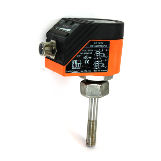
- Seite 1 All manuals and user guides at all-guides.com Bedienungsanleitung Operating instructions Notice utilisateurs Strömungssensor analog Flow sensor analog Sonde de débit analogique SA1000...
-
Seite 2: Inhaltsverzeichnis
All manuals and user guides at all-guides.com Inhalt 1. Bestimmungsgemäße Verwendung ... . Seite 3 2. Montage ....... Seite 4 3. -
Seite 3: Bestimmungsgemäße Verwendung
All manuals and user guides at all-guides.com 1. Bestimmungsgemäße Verwendung Der Strömungssensor erfaßt die Strömungsgeschwindigkeit von Wasser und setzt sie in ein analoges Ausgangssignal um (4 ... 20mA). Zusätzlich zeigt er die aktuelle Strömungsgeschwindigkeit durch eine LED-Kette an. Einsatzbereich: • Wasser und wäßrige Lösungen; •... -
Seite 4: Montage
All manuals and user guides at all-guides.com 2. Montage Um Fehlfunktionen zu vermei- den, müssen Mindestabstände zwischen Strömungswächter min. und Krümmungen, Ventilen, 3 x D Reduzierungen u. ä. eingehalten werden: • Mindestens 5 mal min. 5 x D Rohrdurchmesser an der Anströmseite (A). - Seite 5 All manuals and user guides at all-guides.com Schritt 2 Setzen Sie den Strömungs- w ä c h t e r m i t K o n t e r m u t t e r, O-Ring und Druckscheibe in die Muffe ein und schrauben Sie ihn bis zum Anschlag ein.
-
Seite 6: Elektrischer Anschluß
All manuals and user guides at all-guides.com 3. Elektrischer Anschluß Das Gerät darf nur von einer Elektrofachkraft installiert werden. Befolgen Sie die nationalen und internationalen Vorschriften zur Errichtung elektrotechnischer Anlagen. Spannungsversorgung nach EN50178, SELV, PELV. Schalten Sie die Anlage spannungsfrei bevor Sie das Gerät anschließen. -
Seite 7: Inbetriebnahme / Betrieb / Wartung
All manuals and user guides at all-guides.com 4. Inbetriebnahme / Betrieb / Wartung Prüfen nach Montage, elektrischem Anschluß Programmierung, ob das Gerät sicher funktioniert. Nach dem Einschalten der Versorgungsspannung leuchten alle LEDs auf und verlöschen wieder schrittweise.* Danach ist das Gerät betriebsbereit. -
Seite 8: Function And Features
All manuals and user guides at all-guides.com 1. Function and features The flow sensor detects the flow velocity of water and converts it into an analog output signal (4 ... 20 mA). In addition a row of LEDs indicates the current flow velocity. Applications: •... -
Seite 9: Installation
All manuals and user guides at all-guides.com 2. Installation To avoid malfunction a minimum distance between the flow mon- itor and bends, valves, changes min. in cross-section or such like must 3 x D be observed: • Min. 5 x pipe diameter upstream (A). - Seite 10 All manuals and user guides at all-guides.com Step 2 Insert the flow monitor with lock nut, O-ring seal and compression washer into the bush and screw it in completely using the full thread. O-ring seal compr. washer lock nut Step 3 Position the flow monitor (in the longitudinal pipe axis or trans- verse to it) and fasten the lock...
-
Seite 11: Electrical Connection
All manuals and user guides at all-guides.com 3. Electrical connection The unit must only be connected by an electrician. The national and international regulations for the installation of electrical equipment must be observed. Voltage supply to EN50178, SELV, PELV. The device shall be supplied from an isolating transformer hav- ing a secondary Listed fuse rated as noted in the following table. -
Seite 12: Installation And Set-Up / Operation / Maintenance
All manuals and user guides at all-guides.com 4. Installation and set-up / operation / maintenance After mounting, wiring and setting check whether the unit operates correctly. When the supply voltage is applied, all LEDs light and go off one after the other.* The unit is then ready for operation. -
Seite 13: Fonctionnement Et Caractéristiques
All manuals and user guides at all-guides.com 1. Fonctionnement et caractéristiques La sonde de débit détecte la vitesse de circulation de l'eau et la convertit en un signal de sortie analogique (4 ... 20 mA). De plus, une rampe de LED affiche la vitesse actuelle du fluide. Applications: •... -
Seite 14: Montage
All manuals and user guides at all-guides.com 2. Montage Afin d’éviter un mauvais fonc- tionnement une distance mini- min. 3 x D mum doit être respectée entre la sonde et les coudes, vannes, changements de section etc. min. • Min. 5 x diamètre de la cana- 5 x D lisation en amont (A). - Seite 15 All manuals and user guides at all-guides.com Pas 2 Insérer le détecteur de circulation de fluides avec contre-écrou, joint torique et rondelle de pression dans le raccord à souder et le visser jusqu'à la batée. joint torique rond. de pres. contre-écrou Pas 3 Positionner le détecteur de circu-...
-
Seite 16: Raccordement Électrique
All manuals and user guides at all-guides.com 3. Raccordement électrique L'appareil doit être monté par un électricien. Les règlements nationaux et internationaux relatifs à l'installa- tion de matériel électrique doivent être respectés. Alimentation selon EN50178, TBTS, TBTP. Mettre l’installation hors tension avant le raccordement. Schéma de branchement: Couleurs des fils conducteurs des 1 BN... -
Seite 17: Mise En Service / Fonctionnement / Maintenance
All manuals and user guides at all-guides.com 4. Mise en service / Fonctionnement / Maintenance Après le montage, le câblage et le réglage vérifier le bon fonctionne- ment de l'appareil. Dès la mise sous tension toutes les LED s'allument et s'éteignent l'une après l'autre.* L'appareil est ensuite opérationnel.