EuroLite AKKU Mini PARty RGBW Spot MK2 Bedienungsanleitung
Dmx-scheinwerfer
Inhaltsverzeichnis
Verfügbare Sprachen
Verfügbare Sprachen
Kapitel
Inhaltsverzeichnis

Verwandte Anleitungen für EuroLite AKKU Mini PARty RGBW Spot MK2


Inhaltszusammenfassung für EuroLite AKKU Mini PARty RGBW Spot MK2
-
Seite 2: Inhaltsverzeichnis
TECHNISCHE DATEN ........... 12 Zubehör ..............12 D00134297, Version 1.0, Stand 23/06/2021 Produkt-Updates, Dokumentation, Software und Support erhalten Sie unter www.eurolite.de. Die neueste Version der Bedienungsanleitung finden Sie im Downloadbereich des Produkts. © 2021 Eurolite. Alle Rechte vorbehalten. Dieses Dokument darf ohne schriftliche Genehmigung des Copyrightinhabers weder ganz noch teilweise reproduziert werden. -
Seite 3: Einleitung
Wenn Sie nachfolgende Hinweise beachten, sind wir sicher, dass Sie über viele Updates, Support und Jahre Freude an Ihrem Kauf haben werden. Diese Bedienungsanleitung zeigt News zur Marke. Sie Ihnen, wie Sie Ihr neues Produkt von Eurolite installieren, in Betrieb nehmen finden all das und vieles und nutzen. mehr auf unserer Website. -
Seite 4: Wichtige Sicherheitshinweise
WICHTIGE SICHERHEITSHINWEISE WARNUNG! Lesen Sie aufmerksam die Sicherheitshinweise und benutzen Sie das Produkt nur wie in dieser Anleitung beschrieben, damit es nicht versehentlich zu Verletzungen oder Schäden kommt. Verwendungszweck – Bei diesem Gerät handelt es sich um einen LED-Projektor, mit dem sich dekorative Lichteffekte erzeugen lassen. -
Seite 5: Anschlüsse Und Bedienelemente
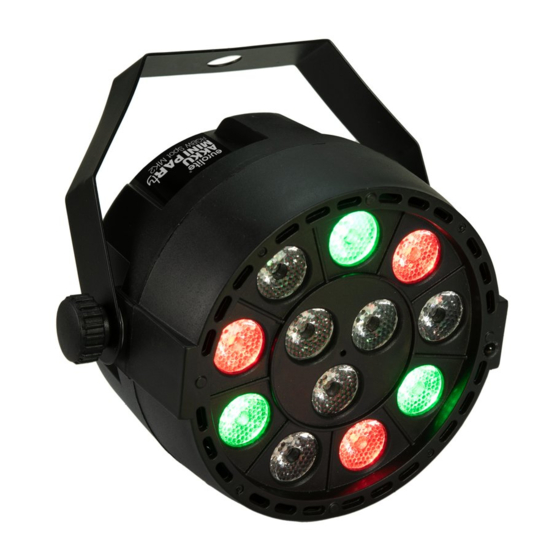
ANSCHLÜSSE UND BEDIENELEMENTE (1) Feststellschraube (2) Linsen/LEDs (3) Infrarotsensor für die Fernbedienung (4) Montagebügel (5) Ein-/Ausschalter (6) DMX-Eingang (7) Ladeanzeige (8) Anschluss Ladenetzteil (9) LED-Display mit Bedientasten (10) DMX-Ausgang 5 • DE... -
Seite 6: Inbetriebnahme
INBETRIEBNAHME Montage Das Gerät kann frei aufgestellt werden. Ein als Zubehör erhältlicher Ständer erleichtert das Aufstellen am Boden. Es ist auch möglich, das Gerät über den Bügel an der Wand oder Decke zu montieren. Achten Sie dabei darauf, dass Sie Schrauben und Dübel entsprechend der Wand-/Deckenbeschaffenheit und mit ausreichender Tragfähigkeit verwenden. -
Seite 7: Bedienung
BEDIENUNG Nach dem Aufladen und Einschalten ist das Gerät betriebsbereit. Das Display zeigt die zuletzt eingestellte Betriebsart. Nehmen Sie nun die notwendigen Menüeinstellungen für die jeweilige Betriebsart mit den Bedientasten vor. Auch wenn Sie das Gerät ausschalten, bleiben alle Einstellungen gespeichert. Menüstruktur Die Wahl der Betriebsart erfolgt über das Display und die Bedientasten MENU, UP, DOWN und ENTER. -
Seite 8: Standalone-Betrieb
STANDALONE-BETRIEB Statische Farben Im Farbmodus A1 strahlt das Gerät konstant in einer von 18 vorgegebenen Farbkombinationen. Drücken Sie die Taste MENU so oft, bis das Display die Betriebsart A1.XX anzeigt. Wählen Sie die gewünschte Farbkombination mit den Tasten UP bzw. DOWN aus: Anzeige LEDs Anzeige... -
Seite 9: Strobe-Effekt
Strobe-Effekt Im Modus A5 stehen 19 farbige Strobe-Effekte zur Verfügung. Drücken Sie die Taste MENU so oft, bis das Display die Betriebsart A5.XX anzeigt. Wählen Sie die gewünschte Farbkombination mit den Tasten UP bzw. DOWN aus. Drücken Sie dann die Taste ENTER (XX fängt an zu blinken), und stellen Sie die Blitzgeschwindigkeit mit den Tasten UP bzw. -
Seite 10: Master/Slave-Betrieb
MASTER/SLAVE-BETRIEB Es lassen sich mehrere Geräte zusammenschalten (max. 32). Das Hauptgerät (Master) kann dann alle Nebengeräte (Slave) synchron steuern ohne die Notwendigkeit eines DMX-Controllers. Die Geräte müssen auf die jeweilige Betriebsart eingestellt werden. Konfigurieren Sie zuerst alle Slave-Geräte vor dem Anschluss an das Master-Gerät. Stellen Sie dazu bei allen Slave-Geräten die DMX-Startadresse im Menüpunkt DMX d auf 1. -
Seite 11: Dmx-Betrieb
DMX-BETRIEB Anzahl der DMX-Kanäle und DMX-Startadresse einstellen Für den Betrieb über einen Controller mit DMX512-Protokoll verfügt das Gerät über 6 Steuerkanäle. Es kann aber auch in einen Modus mit 4 Kanälen umgeschaltet werden, wenn andere Funktionen benötigt werden. Damit das Gerät vom Controller angesteuert werden kann, muss außerdem die DMX-Startadresse eingestellt werden. -
Seite 12: Technische Daten
Zubehör EUROLITE FS-1 Floorstand, Stahl, schwarz Best.-Nr. 5900698A EUROLITE TPC-10 Klammer, silber Best.-Nr. 59006856 EUROLITE Sicherungsseil A 3x600mm bis 5kg, silber Best.-Nr. 58010310 EUROLITE DMX Kabel XLR 3pol 3m sw Best.-Nr. 3022785H PSSO DMX Kabel XLR 3pol 3m sw Neutrik Best.-Nr.